Table of Contents
Advertisement
Quick Links
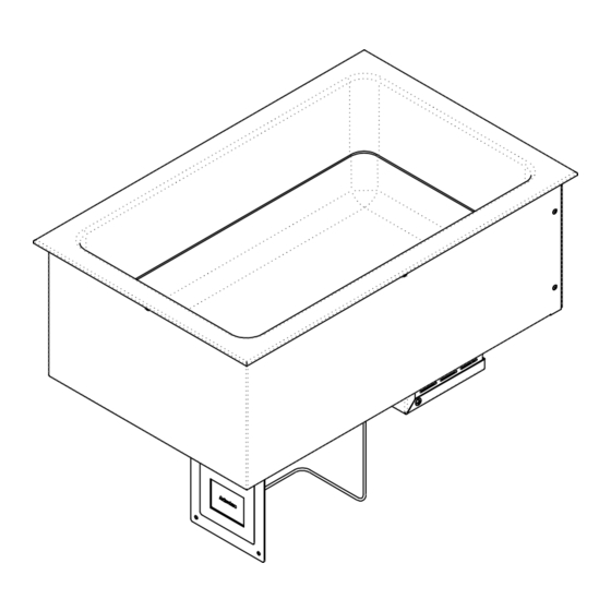
Drop-In Waterless Well
Model:
WW-1
CAUTION:
WARNING for CA residents: go to www.dukemfg.com/prop65 for prop 65 warning
Please read this manual completely before attempting
to install, operate or service this equipment
This manual is Copyright © 2020 Duke Manufacturing Co. All rights reserved.
Reproduction without written permission is prohibited. Duke is a registered
trademark of the Duke Manufacturing Co.
Installation and
Operation Manual
P/N 229894
REV B 10/20/2020
Advertisement
Table of Contents

Related Manuals for Duke WW-1


Summary of Contents for Duke WW-1
- Page 1 WARNING for CA residents: go to www.dukemfg.com/prop65 for prop 65 warning This manual is Copyright © 2020 Duke Manufacturing Co. All rights reserved. Reproduction without written permission is prohibited. Duke is a registered trademark of the Duke Manufacturing Co.
-
Page 2: Table Of Contents
Installation and Operation of: Drop-In Waterless Well TABLE OF CONTENTS Important Safety Instructions ........................2-3 Electrical ................................... 4 Introduction ................................5 Receiving and Inspection ............................ 5 Specifications ................................6 Wire Diagrams ................................. 7 Installation ................................8 Operation ................................9-10 Cleaning ...................................11 Troubleshooting ..............................11 IMPORTANT SAFETY INSTRUCTIONS Throughout this manual, you will find the following safety words and symbols that signify... - Page 3 1. This device may not cause harmful interference, and 2. This device must accept any interference received, including interference that may cause undesired operation. • Changes or modifications to this equipment not expressly approved by the DUKE Manufacturing Co. will void the user’s authority to operate the equipment.
-
Page 4: Electrical
Installation and Operation of: Drop-In Waterless Well WARNING ELECTRICAL SHOCK HAZARD UNIT MUST BE SAFETY GROUNDED, EARTHED. DO NOT MODIFY, DEFEAT ELECTRICAL CONNECTIONS OR ALTER PLUG. ELECTRICAL CONNECTIONS BEFORE CONNECTING THE UNIT TO THE POWER SOURCE, VERIFY THAT THE VOLTAGE AND PHASE OF THE POWER SOURCE ARE IDENTICAL TO THE VOLTAGE AND PHASE INFORMATION ON THE DATA LABEL. -
Page 5: Introduction
Installation and Operation of: Drop-In Waterless Well INTRODUCTION Important to Note: • This unit has been designed to hold and maintain your hot products to the NSF4 standard. • Wells can be expected to reach set point temperature within a 30 to 60-minute time frame. *CAUTION* NEVER add water RECEIVING AND INSPECTION UNPACKING UNIT... -
Page 6: Specifications
Control Cutout ELECTRICAL SPECIFICATIONS: Agency Listings: 4.97” Volts Watts Amps NEMA 60Hz Model 4.97” 4.53” WW-1-120 5-15 UL/ANSI NSF4 WW-1-208/240 208/240 500/665 2.4/2.8 6-20 4.53” DIMENSIONS: Freight Class: 100 Cutout Crated Ship Cube Height Width Length Weight Width Length Model Crated lbs. -
Page 7: Wire Diagrams
Installation and Operation of: Drop-In Waterless Well WIRE DIAGRAMS Waterless Well 120V Configuration Holding Well RTD Temp Sensor CAN PCB CAN_H CAN_H CAN_L CAN_L IOA PCB IOC-G IOC-G Remote Touch Screen Display 2.8" Display 2.8" Display Line Cord NEMA 5-15 229411 Waterless Well 208 / 240V 1 Ph Holding Well... -
Page 8: Installation
Installation and Operation of: Drop-In Waterless Well INSTALLATION Risk of electrocution! Device may cause injuries due to improper installation! Before installation, check the data of the local power grid with the technical specifications of the unit (see nameplate). Connect the device only if they match! Follow the safety instructions! •... - Page 9 Installation and Operation of: Drop-In Waterless Well OPERATION Step 1 Step 3 Press power button to turn on unit and place Display changes to “READY” after the Dry Well silcone liner provided in unit reaches temperature for preset. Step 2 Step 4 After power on the runtime screen appears.
- Page 10 Installation and Operation of: Drop-In Waterless Well OPERATION - Changing Settings Step 1 Step 4 Press settings button to enter General Settings Select the lock icon to unlock the presets. Press the √ Screen. and the screen will go pack to general settings. Step 5 Step 2 Select the Presets button to enter the Dry Well...
- Page 11 Installation and Operation of: Drop-In Waterless Well OPERATION - Changing Settings Step 7 Step 10 Using the plus or minus buttons set the new Select the lock icon to lock the presets temperature and touch the check “√” to save. To abort touch the X button.
-
Page 12: Cleaning
Plug in unit Power source circuit breaker tripped Check circuit breaker and reset Corroded or loose connections Check and tighten all connections Phone: 314-231-1130 Duke Manufacturing Co. Toll Free: 1-800-735-3853 2305 N. Broadway www.dukemfg.com Fax: 314-231-5074 St. Louis, MO 63102...
Need help?
Do you have a question about the WW-1 and is the answer not in the manual?
Questions and answers