Table of Contents
Advertisement
MODELS
RFHU-22
RFHU-23
RFHU-24
RFHU-32
RFHU-34
RFHU-41
RFHU-42
CAUTION:
WARNING for CA residents: go to www.dukemfg.com/prop65 for prop 65 warning
U.S. and Foreign Patents Pending
Please read this manual completely before attempting
to install, operate or service this equipment
This manual is Copyright © 2022 Duke Manufacturing Co. All rights reserved.
Reproduction without written permission is prohibited. Duke is a registered
trademark of the Duke Manufacturing Co.
Installation and
Operation Manual
REV F 05/20/2022
P/N 229787
Advertisement
Table of Contents

Related Manuals for Duke READYFLEX RFHU-22


Summary of Contents for Duke READYFLEX RFHU-22
- Page 1 WARNING for CA residents: go to www.dukemfg.com/prop65 for prop 65 warning This manual is Copyright © 2022 Duke Manufacturing Co. All rights reserved. Reproduction without written permission is prohibited. Duke is a registered P/N 229787 trademark of the Duke Manufacturing Co.
-
Page 2: Table Of Contents
RFHU Operator’s Manual TABLE OF CONTENTS Manufacturer’s Introduction ............................3 Important Safety Instructions ..........................4-5 Installation ..................................6 Stacking Units .................................7 Multipan Flexible Lid Option .............................8 RFHU Operating Instructions ............................9 Overview ......................................9 Preheating ......................................11 Faults ........................................11 Units With Timer Bars ..................................12 RFHU Daypart Menu ..................................13 Settings ..................................14 Menu ........................................14... -
Page 3: Manufacturer's Introduction
The Duke ideal holding curve, the DNA of the RFHU, has been developed, improved, and refined since Duke introduced the first product holding unit in 1999. Utilizing the innovative top and bottom patented Duke technology HeatSinksTM, extended hold times with improved food quality and consistency are achieved. -
Page 4: Important Safety Instructions
• This equipment should be serviced by qualified personnel only. Contact the nearest Duke authorized service facility for adjustment or repair. • Do not block or cover any openings on the unit. - Page 5 RFHU Operator’s Manual IMPORTANT SAFETY INSTRUCTIONS The following warnings and cautions appear throughout this manual and should be carefully observed. • Turn the unit off, disconnect the power source and allow unit to cool down before performing any service or maintenance on the unit. •...
-
Page 6: Installation
RFHU Operator’s Manual INSTALLATION UNPACKING UNIT The following minimum clearances must be Inspect the shipping carton and/or container, maintained between the warmer and any carefully noting any exterior damage on the combustible or non-combustible substance: delivery receipt; also note any damage not evident on the outside of the shipping container (concealed Unit Clearance... -
Page 7: Stacking Units
RFHU Operator’s Manual STACKING UNITS The RFHU is designed to allow limited stacking capabilities. This section outlines how to safely stack the holding unit. Step 1 Remove the base pan from the unit that will be on top. The pan is held in place by four screws on the bottom of the unit. -
Page 8: Multipan Flexible Lid Option
RFHU Operator’s Manual MULTIPAN FLEXIBLE LID OPTION To install the lid, with its support flanges upward lead the tabs over the slots of the lid support brackets. Slide it all the way in until the lid drops into position, rest on the supports, and is retained front to back. It's as easy as that. -
Page 9: Rfhu Operating Instructions
Different types of information are found on the boot screen will appear first for 2 or 3 seconds. This runtime screen. Details below. will display the Duke Logo along with the firmware version number of the RFHU. RUNTIME SCREEN When the unit first boots each well will contain a After the RFHU has loaded the runtime screen will preheating icon. - Page 10 RFHU Operator’s Manual RFHU OPERATING INSTRUCTIONS - Continued Each recipe is programmed with a “hold time”. The Three-day part menus are available to be selected hold time can be configured for any time between on the runtime screen. 1 minute to 720 minutes. Pressing on any well will When selected these will change the recipe display.
-
Page 11: Preheating
RFHU Operator’s Manual RFHU OPERATING INSTRUCTIONS - Continued PREHEATING When the RFHU first boots each well will contain a preheating icon. This indicates the well is heating to temperature. When the recipe temperature is reached the preheat icon will clear and the well will be ready for use. -
Page 12: Units With Timer Bars
RFHU Operator’s Manual RFHU OPERATING INSTRUCTIONS - Continued RFHU DAYPART MENU Units with optional Timer bar To choose another menu, select the Menu Selector. TO ENSURE OPTIMAL HOLD QUALITY, THE USER This will display the Menu screen. Select another WOULD PRESS THE BUTTON ON THE TIMER BAR Menu number and then back to the runtime CORRESPONDING WITH THE PAN LOCATION TO screen. -
Page 13: Rfhu Daypart Menu
RFHU Operator’s Manual RFHU OPERATING INSTRUCTIONS - Continued • ENSURE PROPER HEAT SINK COVERS ARE INSERTED INTO THE CORRECT LOCATION (BROILED AND MOISTURE SENSITIVE PRODUCTS ONLY). • ENSURE METAL TRIVETS ARE INSERTED INTO THE PANS FOR FRIED PRODUCTS. • UPON TURNING ON, ALLOW THE HOLDING UNIT TO HEAT FOR AT LEAST 30 MINUTES OR UNTIL THE TEMPERATURE DISAPPEARS AND THE TIMER BARS DISPLAY THE PRE PROGRAMMED PRODUCT NAMES. -
Page 14: Settings
RFHU Operator’s Manual RFHU OPERATING INSTRUCTIONS - Continued SETTINGS Several Settings are available on the RFHU. To enter the Settings menu click on the cog icon ( ) which is found in the lower right hand corner of the runtime screen. Menu PHU Configurator When the user loads the “RFHU Config”... -
Page 15: Language
“Language” Setting. This is reserved for future use both top and bottom heat. To optimize the holding and will allow RFHU users to change the language performance of the Duke ReadyFlex unit additional display on all screens. temperature adjustments may be necessary. -
Page 16: Help
RFHU Operator’s Manual RFHU OPERATING INSTRUCTIONS - Continued Help Tools Menu When selecting Help option the Help screen will The following configurations are available on the TOOLS load with a QR code. When scanned this will link to menu. this manual hosted on the cloud. Network The Network Config option will allow the RFHU network connection to be configured. - Page 17 RFHU Operator’s Manual RFHU OPERATING INSTRUCTIONS - Continued The current network selection will be highlighted, To connect to a WiFI SSID click on the SSID name. either Ethernet or WiFi. For example: The Wifi SSID password will then be required. Press anywhere within the “Enter Password”...
- Page 18 RFHU Operator’s Manual RFHU OPERATING INSTRUCTIONS - Continued Once entered select “OK” on the on-screen keyboard followed by the check button to attempt to join the WiFi SSID. If the WiFi password is incorrect the RFHU will not join the WiFi network. If the WiFI password is correct the RFHU will join the network and the RFHU will be connected.
-
Page 19: Phu Volume
RFHU Operator’s Manual RFHU OPERATING INSTRUCTIONS - Continued PHU Volume Enter PIN "8429" and select and the following screen will be displayed. The PHU Volume option will either enable or disable sound on the RFHU. The slider can be moved either on or off. Select to save and update the PHU Volume Configuration. -
Page 20: Temp Offset
RFHU Operator’s Manual RFHU OPERATING INSTRUCTIONS - Continued When this screen appears the TOP and BOTTOM Temp Offset current temperature offset value will appear. The The Temperature Offset function will allow the actual temperature read from the RFHU for both the temperature offset to be adjusted per ZONE on the top and bottom heaters will also appear. -
Page 21: Iu Mode
RFHU Operator’s Manual RFHU OPERATING INSTRUCTIONS - Continued Re-entering the recipe config screen will display the UI MODE recipe information as a single line recipe name. The UI Mode option found in the Manager menu will allow the user to set the display to either a single line recipe name of 14 characters length or two line recipe name of 6 characters per line. -
Page 22: Multipan
RFHU Operator’s Manual RFHU OPERATING INSTRUCTIONS - Continued When modifying the long recipe name an alpha- MULTIPAN numeric keyboard will appear on the screen and be NOTE: This feature can be utilized when your RFHU used for modification of the recipe name. was ordered with the Flexible 1/3 Size Pan Lid Sys- tem. - Page 23 RFHU Operator’s Manual RFHU OPERATING INSTRUCTIONS - Continued After selecting the Multipan icon the following screen will appear. After selecting the Multipan configuration, the runtime screen will be updated with the Multipan After selecting a configuration, for example “7” the configuration.
- Page 24 RFHU Operator’s Manual RFHU OPERATING INSTRUCTIONS - Continued Re-entering the PHU Config screen can allow other The corresponding runtime screen will then be Multipan configurations to be selected. displayed as the following once wells have been For example; selecting Multipan layout “9” will started.
-
Page 25: Sous Chef Cloud Programming
Name to be defined along with a user login and password. This can be created via the Sous Chef Cloud registration process without the assistance of Duke Customer Service. An option exists for this purpose on the souscheftech.com landing page –... -
Page 26: Usb Programming
RFHU Operator’s Manual RFHU OPERATING INSTRUCTIONS - Continued The “SHOW LEGEND” button can also be used to A list of local recipes found on the RFHU will appear display the full recipe list for the full account. here. These can be edited, added, or deleted using the appropriate function which will update the connected RFHU local recipe set in real-time. - Page 27 RFHU Operator’s Manual RFHU OPERATING INSTRUCTIONS - Continued For the user’s Account an “offline recipe set” will always be available to the user. This information will be saved and be readily available if a USB file is required to be created. The RFHU Configurator is available for well programming.
-
Page 28: Cleaning Guide
RFHU Operator’s Manual CLEANING GUIDE Electrical shock hazard. Do not wash with water jet or hose. DO NOT USE CAUSTIC CLEANERS, ACIDS, AMMONIA PRODUCTS OR ABRASIVE CLEANERS OR ABRASIVE CLOTHS. THESE CAN DAMAGE THE STAINLESS STEEL AND PLASTIC SURFACES. Bottom and sides of warmer wells are very hot and cool slowly. DAILY CLEANING NEVER USE AN ACID BASED CLEANING SOLUTION! MANY... - Page 29 RFHU Operator’s Manual CLEANING GUIDE - continued PROCEDURE 1. Turn unit off, unplug, and allow to cool for 30 minutes. 2. Remove all holding pans and heat sink covers. Wash, rinse, and sanitize at the 3 compartment sink. 3. Allow to air dry. 4.
-
Page 30: Temperature Check Procedure
RFHU Operator’s Manual TEMPERATURE CHECK PROCEDURE 1. A digital temperature meter that has been 5. All temperature controls exhibit a swing in calibrated must be used to get an accurate temperature as the control cycles on and off temperature reading. Use a thermocouple while regulating to the set point. -
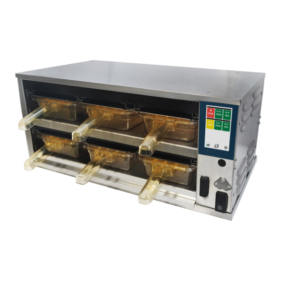
Page 31: Rfhu Specification
RFHU Operator’s Manual RFHU SPECIFICATIONS Height Width Depth RFHU-23 Shown Above ELECTRICAL SPECIFICATION/CORD RATING (TOP AND BOTTOM HEAT) 120V - 60Hz 208/240 V - 60Hz 220/240V - 50/60Hz Model Amps NEMA Amps NEMA Amps Schuko RFHU-22 5-15P 5.8/6.7 6-15P CEE7 VII RFHU-23 5-15P 8.7/10... -
Page 32: Wire Diagrams
RFHU Operator’s Manual WIRE DIAGRAMS 2X2 - TOP & BOTTOM HEAT ELC0541 Rev. D Wire Diagram – RFHU 2x2 Front Timer Bar Well 1 & 3 OPTIONAL Well 2 & 4 *Top & Bottom Heat RED (5V) WHT (CAN_L) BLU (CAN_H) BLK (GND) Antenna Well 2 &... - Page 33 RFHU Operator’s Manual WIRE DIAGRAMS 2X3 - TOP & BOTTOM HEAT ELC0539 Rev F Wire Diagram - RFHU 2x3 * Top & Bottom Heat OPTIONAL Well 1 & 4 Well 2 & 5 Well 3 & 6 Front Timer Bar (5V) 5Vdc CAN_L...
- Page 34 RFHU Operator’s Manual WIRE DIAGRAMS 2X3 - BOTTOM HEAT 2 2 1-6 1 5 2 2 1-6 1 5 2 2 1-6 1 5 2 2 1-6 1 5 2 2 1-6 1 5 2 2 1-6 1 5 DMX PCB Main Control DMX PCB Main Control...
- Page 35 RFHU Operator’s Manual WIRE DIAGRAMS 2X4 - TOP & BOTTOM HEAT Wire Diagram - RFHU 2x4 ELC0535 Rev C * Top & Bottom Heat OPTIONAL Well 1 & 5 Well 2 & 6 Well 3 & 7 Well 4 & 8 Front Timer Bar 5Vdc RED (5V)
- Page 36 RFHU Operator’s Manual WIRE DIAGRAMS 4X1 TOP & BOTTOM HEAT ELC0676 Rev A Well 1 Wire Diagram - RFHU 4x1 (5V) Front Top (CAN_L) Timer Bar (CAN_H) Top & Bottom Heat (GND) Well 2 OPTIONAL Well 3 (5V) Front Bottom (CAN_L) Timer Bar (CAN_H)
- Page 37 RFHU Operator’s Manual WIRE DIAGRAMS 4X2 TOP & BOTTOM HEAT ELC0536 Rev d Wire Diagram - RFHU 4x2 * Top & Bottom Heat Well 1 & 3 Well 2 & 4 Front Top Timer Bar RED (5V) WHT (CAN_L) OPTIONAL BLU (CAN_H) BLK (GND) Front Bottom Timer Bar...
- Page 38 RFHU Operator’s Manual WIRE DIAGRAMS - 2X4 & 4X2 BOTTOM HEAT Wire Diagram – RFHU 2x4 & 4x2 ELC0537 Rev D * Bottom Heat OPTIONAL Well 1 & 5 Well 2 & 6 Well 3 & 7 Well 4 & 8 2x4 Front Timer Bar 5Vdc RED (5V)
- Page 39 RFHU Operator’s Manual WIRE DIAGRAMS - 3X2 BOTTOM HEAT ONLY ELC0540 Rev D Wire Diagram - RFHU 3x2 * Bottom Heat only Well 1 & 2 OPTIONAL Top Front Timer Bar RED (5V) WHT (CAN_L) BLU (CAN_H) BLK (GND) OPTIONAL Bottom Front Timer Bar Well 3 &...
- Page 40 RFHU Operator’s Manual Wire Diagram – RFHU 3x2 ELC0538 Rev C * Top & Bottom Heat Well 1 & 2 OPTIONAL (5V) Front Top (CAN_L) Timer Bar (CAN_H) (GND) OPTIONAL Well 3 & 5 Well 4 & 6 (5V) Front Bottom (CAN_L) Timer Bar (CAN_H)
- Page 41 RFHU Operator’s Manual WIRE DIAGRAMS 3X4 RFHU 3x4 Wire Diagram ELC0533 Rev A 4/26/2022 Well 1 & 2 Well 3 & 4 Optional (5V) Front Top 5Vdc CAN_L Timer Bar (CAN_L) CAN_H (CAN_H) (GND) Optional Well 5 & 9 Well 6 & 10 Well 7 &...
- Page 42 RFHU Operator’s Manual THIS PAGE LEFT BLANK...
- Page 43 RFHU Operator’s Manual THIS PAGE LEFT BLANK...
- Page 44 Phone: 314-231-1130 Duke Manufacturing Co. Toll Free: 1-800-735-3853 2305 N. Broadway www.dukemfg.com Fax: 314-231-5074 St. Louis, MO 63102...
Need help?
Do you have a question about the READYFLEX RFHU-22 and is the answer not in the manual?
Questions and answers