urmet domus iPerTAlk 1375 Quick Start Manual
Hide thumbs
Also See for iPerTAlk 1375:
- Installation and configuration manual (100 pages) ,
- Quick user manual (16 pages) ,
- Installation handbook (13 pages)

Related Manuals for urmet domus iPerTAlk 1375


Summary of Contents for urmet domus iPerTAlk 1375
- Page 1 Mod. 1375 DS1375-008B LBT20526 IPERTALK IP-PBX IP-PBX IPERTALK Sch./Ref. 1375/10 - 1375/11 - 1375/12 GUIDA RAPIDA PER L’UTILIZZO QUICK START GUIDE FOR USE...
-
Page 2: Table Of Contents
ITALIANO 1. DESCRIZIONE GENERALE ........................3 2. CONTENUTO DELLA CONFEZIONE ....................... 3 3. DESCRIZIONE DEI COMPONENTI......................3 4. INSTALLAZIONE ............................4 5. DESCRIZIONE LED, CONNETTORI E PULSANTI ................... 6 LED DI ACCENSIONE (1) ....................... 6 LED DI STATO (2) ........................... 6 LED PORTA LAN (6) ........................ -
Page 3: Descrizione Generale
1. DESCRIZIONE GENERALE iPerTAlk IP-PBX permette la gestione di impianti telefonici VoIP/SIP mediante l’interconnessione diretta verso operatori VoIP remoti. Per maggiori informazioni sull’intero sistema iPerTAlk, si consiglia di consultare il libretto di installazione e confi gurazione pubblicato sul sito https://www.urmet.com/it-it/sistemi/telefonia#/ alla categoria “Sistemi IP” oppure scansionando, con la fotocamera del proprio smartphone o tablet, il QR-Code in ultima pagina. -
Page 4: Installazione
4. INSTALLAZIONE ATTENZIONE: L’installazione del sistema deve essere eseguita esclusivamente da personale qualifi cato. Si consiglia di consultare le informazioni di Sicurezza nell’apposita sezione del presente libretto istruzione. Per effettuare la prima installazione del dispositivo, è necessario seguire i seguenti passi: Aprire lo sportello (4) facendolo scorrere verso l’esterno. - Page 5 Esercitando una lieve pressione, inserire la batteria (7) nell’alloggiamento batteria (8), seguendo la giusta polarità. Collegare l’alimentatore al connettore di alimentazione (9). Utilizzare, in base alla posizione del dispositivo, i fori di prerottura (A) di destra o di sinistra, predisposti per il passaggio del cavo dell’alimentatore.
-
Page 6: Descrizione Led, Connettori E Pulsanti
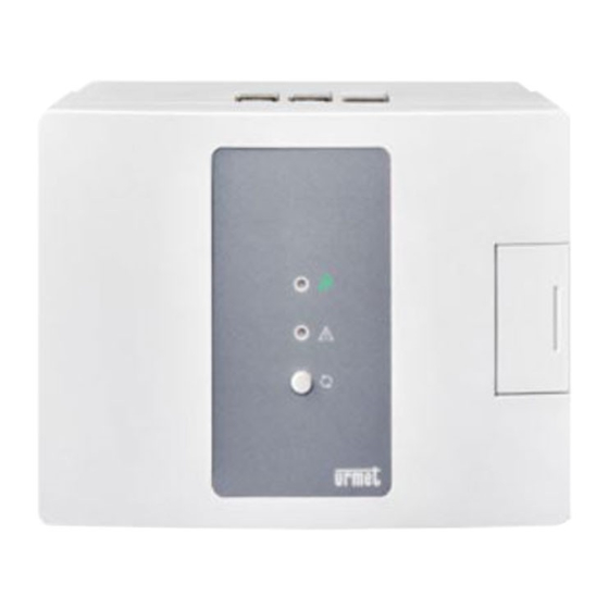
5. DESCRIZIONE LED, CONNETTORI E PULSANTI LED DI ACCENSIONE (1) Colore del led Descrizione Verde Dispositivo alimentato Led spento Dispositivo non alimentato LED DI STATO (2) Colore del led Descrizione Verde fi sso Sistema funzionante con licenza installata Rosso fi sso Sistema non funzionante 1 lampeggio Blu Connessione ad Internet non disponibile... -
Page 7: Connessione Alla Rete
Numero di chiamate simultanee Banda richiesta (upload & download) 85 kbps 174 kbps 358 kbps 696 kbps 7. CONNESSIONE ALLA RETE Seguire la seguente procedura per effettuare i collegamenti di rete. Collegare un’estremità del cavo Ethernet alla porta LAN dello switch, l’altra estremità alla porta LAN (6) del dispositivo. -
Page 8: Distanze Massime E Sezioni Cavi
8. DISTANZE MASSIME E SEZIONI CAVI Tipologia di collegamento Distanza max Sezione min - max 100 m (*) CAT5e (#) (*) La distanza massima consentita è quella defi nita dalla norma IEEE 802.3 per le reti Fast Ethernet (100 Mb/s) con connessioni in cavo UTP CAT5, la quale prevede che tra due dispositivi Ethernet collegati tra loro non vengano superati i 100 m. - Page 9 6. Effettuando l’accesso in automatico viene visualizzata la pagina principale. 7. Sul menù superiore premere su Sistema e selezionare la voce Wizard, che permette la confi gurazione guidata e semplifi cata di tutti i parametri principali. Nella seguente tabella sono riportate le funzionalità confi gurabili di cui si possono trovare opportuni riferimenti nel libretto di installazione e confi...
- Page 10 9. Procedere al caricamento della licenza dal proprio PC scegliendo il fi le con nome “UUID iPerTAlk.lic” nel disco e premendo il tasto “Carica”. 10. Attendere il riavvio dell’applicazione ed effettuare nuovamente il login. Accedere alla pagina Wizard dal menù di Sistema. 11.
-
Page 11: Accesso A Rete Telefonica
15. I telefoni acquisiranno automaticamente un numero di interno nel sistema. • Se è disponibile un server DHCP nella rete: i telefoni acquisiranno automaticamente i parametri di rete senza nessuna operazione da parte dell’installatore. • Se non è disponibile un server DHCP nella rete: confi gurare la VLAN ID 5 e attendere il completamento della confi... -
Page 12: Videotelefono U.talk Touch 7" Sch. 1375/815
5. Premere il pulsante SALVA. Il dispositivo effettuerà il riavvio, se iPerTAlk è connesso alla stessa rete fi sica, dello stesso switch, il dispositivo riceverà un IP dal server DHCP a bordo del sistema iPerTAlk. 10.2 VIDEOTELEFONO U.TALK TOUCH 7” SCH. 1375/815 Per confi... -
Page 13: English
ENGLISH 1. GENERAL DESCRIPTION ........................14 2. CONTENT OF THE BOX ........................14 3. DESCRIPTION OF COMPONENTS ....................... 14 4. INSTALLATION ............................15 5. DESCRIPTION OF LEDS, CONNECTORS AND BUTTONS ..............17 POWER LED (1) ..........................17 STATUS LED (2) ........................... 17 LAN PORT LED (6) ........................ -
Page 14: General Description
1. GENERAL DESCRIPTION iPerTAlk IP-PBX can be used to manage VoIP/SIP telephone installations by direct interconnection with remote VoIP operators. For more information on the entire iPerTAlk system, refer to the installation and confi guration booklet published on https://www.urmet.com/en-us/Systems/telephony#/ section or by scanning, with the camera of your smartphone or tablet, the QR-Code on the last page. -
Page 15: Installation
4. INSTALLATION IMPORTANT: The system must be installed by qualifi ed personnel only. Refer to the safety information in the appropriate section of this instruction booklet. For the fi rst installation of the device, proceed as follows: Open fl ap (4) by making it slide outwards. Undo the screw using a Phillips screwdriver and remove the front cover. - Page 16 By exerting a slight pressure, insert the battery (7) in the battery housing (8), following the correct polarity. Connect the power supply to the power connector (9). According to the position of the device, use the pre-cut holes (A) on the right or on the left, arranged for passing through the power supply cable. Close the previously removed front cover with the screw.
-
Page 17: Description Of Leds, Connectors And Buttons
5. DESCRIPTION OF LEDS, CONNECTORS AND BUTTONS POWER LED (1) LED colour Description Green Device powered LED off Device not powered STATUS LED (2) LED colour Description Green fi xed System working with installed license Red fi xed System not working 1 blue fl... -
Page 18: Connection To The Network
Number of concurrent calls Required bandwidth (upload & download) 85 kbps 174 kbps 358 kbps 696 kbps 7. CONNECTION TO THE NETWORK Follow the procedure below to make network connections. Connect one end of the Ethernet cable to the LAN port on the switch and the other end to the LAN port (6) of the device. -
Page 19: Maximum Distances And Wire Sections
8. MAXIMUM DISTANCES AND WIRE SECTIONS Type of connection Max. distance Min - max section 100 m (*) CAT5e (#) (*) The maximum permissible distance is that defi ned by IEEE 802.3 for Fast Ethernet networks (100 Mb/s) with UTP CAT5 connections, which establishes that the maximum distance between two Ethernet devices connected to each other must be 100 m. - Page 20 6. The main page will appear when logging on automatically. 7. On the top menu, press System and select the Wizard to proceed with the guided and simplifi ed confi guration of all main parameters. The following table lists the confi gurable features. Refer to the installation and confi guration booklet for more information.
- Page 21 9. Proceed by loading the license from the PC by selecting the fi le called “UUID iPerTAlk.lic” in the disc and pressing “Load”. 10. Wait for the system to boot and login again. Open the Wizard page from the System menu. 11.
-
Page 22: Access To The Telephone Network
13. Enable the “Automatic Confi guration” function and press Save. 14. Connect all telephone devices to the network and wait. 15. The telephones will automatically acquire an extension number in the system. • If a DHCP server is available in the network, the telephones will automatically acquire the network parameters without any operation by the installer. -
Page 23: Videotelephone U.talk Touch 7" Ref. 1375/815
5. Press SAVE. The device will reboot, if iPerTAlk is connected to the same physical network, on the same switch the device will receive an IP address from the DHCP server on the iPerTAlk system on the telephone network, i.e. 10.10.10.x 10.2 VIDEOTELEPHONE U.TALk TOUCH 7”... - Page 24 Per maggiori informazioni sull’installazione, la confi gurazione e l’utilizzo del sistema iPerTAlk scaricare il Libretto di installazione e confi gurazione e la Guida utente scansionando il QR Code riportato di seguito. http://qrcode.urmet.com/default.aspx?prodUrmet=142687&lingua=it For more information on the installation, confi guration and use of the iPerTAlk system, download the Installation and confi...
Need help?
Do you have a question about the iPerTAlk 1375 and is the answer not in the manual?
Questions and answers