Table of Contents
Advertisement
Quick Links
Advertisement
Table of Contents

Related Manuals for Unical ALKON 100 EXT


Summary of Contents for Unical ALKON 100 EXT
- Page 1 ALKON 100 EXT - 115 EXT - 140 EXT INSTALLATION AND SERVICING MANUAL...
- Page 2 http://www.unicalag.it/prodotti/professionale-300/light-commercial-alluminio/1639/alkon-140-ext Provisions for proper disposal of the product At the end of its life cycle the product must not be disposed of as urban waste. It can be taken to a special recycling centre managed by the local authorities, or to a dealer who offers this service. Separate disposal of a domestic appliance avoids possible negative consequences for the environment and human health deriving from inappropriate waste handling and allows the recovery of the materials of which it is made, in order to obtain significant energy and resource savings.
-
Page 3: Table Of Contents
Attention: this manual contains instructions for the exclusive use of the professionally qualified installer and/or maintenance technician in compliance with current legislation. The user is NOT qualified to intervene on the boiler. The manufacturer will not be held liable in case of damage to persons, animals or objects resulting from failure to comply with the instructions contained in the manuals supplied with the boiler. -
Page 4: General Information
Any product repairs must be performed solely by personnel product and must be kept by the user. authorised by Unical, using original spare parts only. Failure to comply with the above can compromise the safety of the appli- ance and void the warranty. -
Page 5: Symbols Used In The Manual
Any other use must be considered improper. For any damage resulting from improper use, UNICAL AG S.p.A. assumes no responsibility. Use according to the intended purposes also includes strict compliance with the instructions in this manual. 1.4 - INFORMATION FOR THE SYSTEM MANAGER The user must be instructed concerning the use and operation of his heating system, in particular: •... -
Page 6: Safety Warnings
1.5 - SAFETY wARNINGS ATTENTION! The boiler cannot be used by children. The boiler can be used by adults and only after having carefully read the user’s ma- nual. Children should be supervised to ensure that they do not play or tamper with the device. -
Page 7: Technical Data Plate
1.6 - TEchnIcAl dATA PlATE The cE marking KEY: 1 = CE monitoring body certifies the compliance of the equipment with the 2 = Type of boiler essential safety requirements defined in the directi- 3 = Boiler model ves and applicable European regulations and that 4 = Number of stars (directive 92/42 EEC) its functioning satisfy applicable technical stan- 5 = (S.N°) Serial Number... -
Page 8: Water Treatment
1.7 - wATER TREATMENT The treatment of the supply water allows to ATTENTION! prevent inconveniences and maintain the ANY DAMAGE TO THE BOILER CAUSED BY functionality and efficiency of the generator THE FORMATION OF FOULING OR BY COR- over time. ROSIVE wATER wILL NOT BE COVERED BY THE wARRANTY. -
Page 9: Boiler Antifreeze Protection
1.8 - BOILER ANTIFREEZE PROTECTION Enabled by default This protection can intervene only if the electricity and gas supplies are connected. If one of the two is not available and upon reset 30 (SMG) a temperature between 2 ÷ 5°C is detected, the appliance will behave as described in tab. -
Page 10: Technical Features And Dimensions
TECHNICAL FEATURES AND DIMENSIONS NOTE! Further details in the section 2.1 - TECHNICAL FEATURES ‘‘Technical Information’’ on the boiler page of the www.unicalag.it website 2.2 - VIEw wITH THE INDICATION OF THE MAIN COMPONENTS Scond Flue gas pressure switch LEGENDA AF/AS N°... -
Page 11: Dimension
2.3 - DIMENSIONS Front view Side view View from below View from above Heating system return G 2’’ Outlet flue inspection Heathing Controller Condensation drain Scond Gas cock DN 32 C.E. = ERROR CODES see Ignition Trasformer PFmin Gas min pressure switch S.E. -
Page 12: Available Flow Rate / Pressure Diagram
2.4 - dIAGRAM OF FlOW RATE/PRESSURE AVAIlABlE FOR InSTAllATIOn Flow rate (l/h) The table provides an indication the flow the pump in function of the Dt of the primary circuit. ALKON 100 EXT ALKON 115 EXT ALKON 140 EXT Power supply in kW... -
Page 13: Operation Data
2.5 - OPERATING DATA ACCORDING TO UNI 10348 and GENERAL FEATURES For the adjustment data: NOZZLES - PRESSURE - DIAGRAMS - FLOW RATES - CONSUMPTION refer to the paragraph ADAP- TATION TO OTHER TYPES OF GAS. ALKON 100 EXT ALKON 115 EXT ALKON 140 EXT... -
Page 14: Data Erp Directive
2.5.1 - DATA ACCORDING TO ErP DIRECTIVE EXT 100 EXT 115 EXT 140 Element Symbol Unit Effective nominal output Pnominale Seasonal energy efficiency to heat ƞ the room Season efficiency class to discharge For ch only and combination boilers: useful heat output Useful Heat Output in high-tempera- ture regime 55,0... -
Page 15: Installation Instructions
INSTALLATION INSTRUCTIONS 3.1 - GENERAL wARNINGS ATTENTION! ATTENTION! If there is dust and/or if there are his boiler is intended solely for the use for aggressive/corrosive vapours present in which it was expressly designed. Any other the installation room, the appliance must use is to be considered improper and there- be protected suitably and must be able to fore dangerous. -
Page 16: Packaging
- Air inlet filter. of children as they are potential sources of danger. - Kit multifunction module SHC Unical AG S.p.A. will not be held liable for damage - Outdoor sensor to persons, animals or objects due to failure to - Sifone (*) comply with the instruction above. -
Page 17: Positioning The Boiler
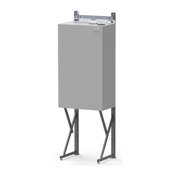
3.5 - POSITIONING IN BOILER ROOM Particular importance should be given to local regulations and laws in terms of boiler room and especially the minimum distance that must be kept clear around the boiler. The installation must conform to the requirements contained in the most recent regulations and laws in terms of boiler room, installations of heating and production of hot water, ventilation, chimneys suitable to discharge the products of combustion of... - Page 18 SUPPORT FRAME (2) optional...
-
Page 19: Flue Gas Exhaust Pipe Connection
3.6 - FlUE GAS EXhAUST PIPE Ø 120 optional adapters for twin flue CONNECTION systems To connect the flue gas exhaust pipe, local and national stand- ards must be observed In the event the boiler is replaced, AlWAYS replace the flue gas pipe as well. -
Page 20: Connections
3.7 - CONNECTION Condensation drain The boiler, during the combustion process, produces conden- 1’’ sation that, through pipe “A”, flows into the trap. The condensation that forms inside the boiler flows into a suitable Danger! drain via pipe “B”. The gas connection must be carried out only by Danger! a qualified installer who must respect and apply Before commissioning the appliance:... - Page 21 This could damage the gaskets and cause noise during operation. Unical will not be held liable for damage to persons, animals or objects due to failure to comply with the above instruction. Pressure in the mains supply must be between 0.5...
-
Page 22: Electrical Connections
3.9 - ElEcTRIcAl cOnnEcTIOnS 00330914 ATTENZIONE! ATTENTION! ACHTUNG! ATENCIÓN! ATTENTIE! UPOZORNÌNÍ! 230 V Danger! Only a qualified technician may perform the electrical installation. Before performing connections or any type of operation on electrical parts, always discon- nect electrical power and make sure that it cannot be reconnected accidentally. - Page 23 Danger! The boiler is equipped with a power cable, boiler Only a qualified technician may perform the installation requires electric al connection to the electrical installation. mains power supply. This connection must be Before performing connections or any type of made up to standard, as required the regulations operation on electrical parts, always discon- in force.
- Page 24 FL Flow switch connection (*) INAIL safety connections Safety Connection - Remove the jumper and connect the cables as indicated - Remove the jumper and connect the cables as indicated between between (Y2 10 and terminal board M2). (Y2 11 and terminal board M2). External probe connection (*) Set up on terminal board, BCM (Y2 6-7).
- Page 25 nOTE: tanks, mixed areas, solar, etc), you must purchase SHC multi- function modules to connect to the local bus for total manage- The boiler is set up for direct flow and storage tank ment through HSCP (and UFLY) heating controller. management.
- Page 26 Control panel remotely NOTE! For more information See Technical Info from site indicated at pag. 2...
-
Page 27: Commissioning
3.10 - COMMISSIONING Commissioning must be done by professionally instruction. qualified personnel. Unical AG S.p.A. will not be Before commissioning the boiler, check that: held liable for damage to persons, animals or objects due to failure to comply with the above... -
Page 28: Measurement Of Combustion Efficiency During Installation
3.11 - MEASUREMENT OF THE COMBUSTION EFFICIENCY DURING INSTALLATION Generator Menu 3.11.1 - CALIBRATION FUNCTION (CHIMNEY SwEEP) ATTENTION! ATTENTION! These functions are explained in Function reserved for After Sale chapter 2.9 (Burner menu) of the Service Centres only. Ufly P. TOUch cOnTROl instal- lation and maintenance manual. -
Page 29: Probes Positioning
3.11.2 - POSITIONING THE PROBES To determine the combustion efficiency one must make the following measurements: ATTENTION! - measurement of the combustion air temperature Remove - measurement of the flue gas temperature and content of cap 2, taken in the relevant hole 2. Insert the CO2 probe Take the measurements with the generator in steady state... - Page 30 (aluminium sections) are well cleaned. NOZZLES - PRESSURE - FLOw RATES TABLE Check the levels of CO2 often, especially with low flow rates. They refer to the boiler with a closed combustion chamber. ALKON 100 EXT Type of Supply Ø...
-
Page 31: Maintenance Instructions
4.1 - INSPECTION AND MAINTENANCE INSTRUCTIONS To assure long-term functioning of your appliance and to avoid Once all maintenance operations are complete altering its approved status, only original Unical spare parts resume boiler operation. must be used. • Open the heating flow and return pipes, as well as the cold water inlet valve (if closed previously). - Page 32 1) Measure the Thermal Capacity using a me- It is recommended to use the products ter and compare the value with that contained purposely created by Unical (see sys- tem protection ACCESSORIES sect. in in table 3.12. The data measured indicates if the domestic price list), being careful the exchanger needs cleaning.
-
Page 33: Adaptation To The Use Of Other Gas
4.3 - ADAPTATION TO THE USE OF OTHER GAS The boilers are produced for the type of gas specifically requested Gas Conversion upon ordering. NOTE! For more information DANGER! See Technical Info The conversion for the operation of the boiler from site indicated at pag. -
Page 34: Operation Parameters Programming
4.4 - PROGRAMMING THE OPERATING PARAMETERS ATTENTION! ATTENTION! These functions are explained Function reserved for After Sale in chapter 2.8 (DEVICES menu) Service Centres only. of the Ufly P. TOUch cOnTROl installation and maintenance manual. PARAMETER BMM MODULE CODE SYMBOL PARAMETER DESCRIPTION U.M. - Page 35 BCM Parameters Code Symbol Description Unit Min. Max. Imp. Fab. Enabled Services Gen: Temp. Max Differential °K 50,0 Burner Hysteresis °K 20,0 CH#1: Minimum Set-point °C 20,0 40.0 35,0 CH#1: Maximum Set-point °C 45,0 85.0 80,0 Input 0/10V Programmable Input #1 Pump: Post-circulation min.
-
Page 36: Wiring Diagram
4.5 - wIRING DIAGRAM eBUS- eBUS- eBUS+ eBUS+ BMM1 PPD1 min1 min2 (FSI) PK eBUS+ GR eBUS- BMM1 Modbus A Modbus B Menu +24V eBUS- eBUS+... - Page 37 BMM2 PPD2 PPD2 min2 (FSI) A1...A9 = Services Connector = Supply Modulating Pump = Modulating pump control = Safety low water pressure switch E. ACC. = Ignition electrode E. RIL. = Detection Electrode = Insert BCM INTC (1) (2) = Switch inhibition INAIL body (1) (2) = Power supply terminal 230 V...
-
Page 38: Error Codes
4.6 - ERROR cOdES Fault that causes the boiler to stop: Fault that does NOT cause the boiler to stop: - The error code is displayed, the boiler has stopped - The error code is displayed, the boiler has a heat- running. - Page 39 SPEED OUT OF Check fan operation (18) and the connections CONTROL Alteration of the fan speed; the speed is above that requested OBSTRUCTION EXHAUST Check Chimney / Ceck siphon FACTORY PARAMETERS Press the unblock key; if the anomaly persists, replace the board. Alteration of the factory parameters due to possible electromagnetic interferences.
- Page 40 - export@unical-ag.com - www.unical.eu Unical declines every responsibility for the possible inaccuracies if owed to errors of transcript or press. Also reserves the right to bring those changes that it will hold necessary to it own products or profits, without jeopardizing its essential characteristics.
Need help?
Do you have a question about the ALKON 100 EXT and is the answer not in the manual?
Questions and answers