
Subscribe to Our Youtube Channel
Related Manuals for Unical ALKON 50 kW


Summary of Contents for Unical ALKON 50 kW
-
Page 1: And Servicing
ALKON 50 kW ALKON 70 kW INSTALLATION AND SERVICING MANUAL 00333009/a - 3 edition - 02/10 ENGLISH... -
Page 2: Table Of Contents
Failure to follow the instructions indicated in this manual, which is supplied with the boiler, could cause injury to persons, animals or damage to property. UNICAL shall not be held liable for any injury and/or damage. CONTENTS GENERAL INFORMATION .................................... -
Page 3: General Information
Any other use of this appliance will be considered improper.UNICAL declines any responsibility for any damages or injuries caused by an improper use; in this case the risk is completely at the user’s responsibility.In order to use the appliance according to the scopes it was designed for it is essential to carefully follow the instructions indicated in this guide. -
Page 4: Safety Warnings
Servicing or repairs of the appliance must be carried out by UNICAL authorised service technicians; UNICAL recommends drawing up a service contract. Bad or irregular servicing could compromise the safe operation of the appliance, and could cause injury to persons, animals or damage to property for which UNICAL shall not be held liable. -
Page 5: Data Badge
General Information DATA BADGE CE Marking The essential requirements of the ElectroMagnetic CompatibilityDirective The CE marking documents that the boilers satisfy: (2004/108/CEE) The essential requirements of the Directive regarding gas appliances (Directive The essential requirements of the BoilersEfficiency Directive ( 92/42/CEE) 90/396/CEE) The essential requirements of the Low Voltage Directive ( 2006/95/CEE) ®... -
Page 6: General Warnings
Please read carefully the instructions contained in this manual as they provide important indications regarding the safe Any repairs must be carried out by Unical authorized installation, use and servicing of this appliance. technicians and using only original spare parts. Non- observance of the above requirement may jeopardize the Keep this manual in a safe place for future reference. -
Page 7: Technical Features And Dimensions
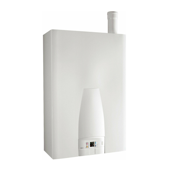
Technical features and dimensions TECHNICAL FEATURES AND DIMENSIONS • Automatic air vent; • Drain condensate siphon • Control panel with electrical protection IP X4D; 2.1 - TECHNICAL FEATURES • eBUS device; • CH temperature selector switch: 30 ÷ 85°C; The ALKON 50/70 boilers are a thermals gas fired units with •... -
Page 8: Dimensions
Technical features and dimensions DIMENSIONS ALKON 50/70 + KIT SAFETY DEVICES + HYDRAULIC HEADER +Y FILTER KIT 1510 DIMENSIONS ALKON 50/70 in BATTERY (n.2 boilers) + KIT SAFETY DEVICES + HYDRAULIC HEADER +Y FILTER KIT 3040... - Page 9 Technical features and dimensions DIMENSIONS ALKON 50/70 in BATTERY (n.3 boilers) + KIT SAFETY DEVICES + HYDRAULIC HEADER +Y FILTER KIT 3726 DIMENSIONS ALKON 50/70 in BATTERY (n.4 boilers) + KIT SAFETY DEVICES + HYDRAULIC HEADER +Y FILTER KIT 4630...
-
Page 10: Main Components
Technical features and dimensions 2.3 - MAIN COMPONENTS ALKON 50 FLUE AIR INTAKE OUTLET MODULATING OPENING PIPE (Ø80 mm) (Ø80 mm) VENT VALVE IGNITION ELECTRODE IGNITION ALUMINIUM HEAT EXCHANGER/ TRANSFORMER CONDENSER OVERHEAT THERMOSTAT PIPE WITH SMOKE FLOW SAMPLING AND TEMPERATURE CONDENSATE SENSOR EVACUATION... - Page 11 Technical features and dimensions ALKON 70 FLUE AIR INTAKE OUTLET MODULATING OPENING PIPE (Ø80 mm) (Ø80 mm) VENT VALVE IGNITION ELECTRODE ALUMINIUM HEAT IGNITION EXCHANGER/ TRANSFORMER CONDENSER OVERHEAT THERMOSTAT PIPE WITH SMOKE FLOW SAMPLING AND TEMPERATURE CONDENSATE SENSOR EVACUATION CONNECTION GAS VALVE RETURN TEMPERATURE...
-
Page 12: Boiler Water Circuit
(only for ALKON 50) modulating pump only for ALKON 70 ONLY FOR THE PUMP KIT SUPPLIED BY 14 Safety valve 6 bar UNICAL 15 Pressure switch against lack of water 00361320 - Kit of MODULATING PUMP, only for ALKON 50 M C.H flow... -
Page 13: Operating Performances
Technical features and dimensions 2.5 - PERFORMANCE DATA For information regarding the adjustment of: INJECTORS - BURNER PRESSURES – DIAPHRAGMS – OUTPUTS – GAS CONSUMPTIONS please refer to the paragraph ADAPTMENT TO THE USE OF OTHER GASES. ALKON 50 ALKON 70 Max heat input 48,5 67,5... -
Page 14: Instructions For The Installer
Instructions for the installer INSTRUCTIONS FOR THE INSTALLER 3.1 - GENERAL WARNINGS WARNING! WARNING! In rooms where there is the presence of This boiler has to be destined for the use for aggressive vapours or dust the appliance which it has been expressively designed for. must operate independently from the air Any other use shall be considered improper present in the boiler’s location room, i.e. -
Page 15: Installation Standards
Instructions for the installer 3.2 - STANDARD CODES FOR INSTALLATION Moreover, the boiler must be installed in accordance to all the The appliance must be installed in compliance to the regulations regarding the boiler room, the building regulations instructions contained in this manual. and the prescriptions regarding central heating plants in force in the country the boiler is installed. -
Page 16: Packaging
Keep the packaging material (cardboard box, plastic bags, polyester protection etc.) out of the reach of children as they can be dangerous. UNICAL refuses all liability for injury to persons, animals or damage to property deriving from not having respected the above mentioned recommendations. -
Page 17: Installation On Existing Systems
If any part of the system is concealed from view the gas As a safety measure against gas leaks, Unical soundness test must be carried out before covering the pipes. recommends installing a surveillance and... -
Page 18: Connection Return And Flow System Pipes
Instructions for the installer 3.7 - FLOW AND RETURN PIPE CONNEC- TIONS The CH flow and return circuits have to be connected to the 1” or 1’’¼ boiler via the respective connections as indicated on page 16. When determining the size of the CH circuit pipes it is essential to bear in mind the pressure losses induced by any of the system’s components and by the configuration of the same system. -
Page 19: Determination Of Primary Boiler Pump Or Boiler Pump System
Instructions for the installer 3.8 - DETERMINATION OF PRIMARY BOILER PUMP OR BOILER SYSTEM PUMP The boiler pump must have a delivery head which can ensure The size of the pumps must be determined the water flow rate as shown in the diagram “Water pressure by installers or technical engineers losses”. -
Page 20: Supplemental Safety, Security And Control Devices
Instructions for the installer 3.9 - SUPPLEMENTAL SAFETY, PROTECTIVE AND CONTROL DEVICES PRESCRIBED BY THE GOVERNMENT DECREE 01-12-1975 AND RELATIVE APPLICABLE TECHNICAL SPECIFICATIONS (CONTAINED IN THE “RACCOLTA R EDITION 1982”) CERTIFICATION OF THE SUPPLEMENTAL SAFETY DEVICES: CONTROL DEVICES Several notified bodies prescribe supplemental safety Pressure indicator with shock absorber tube and devices. -
Page 21: Safety Pressure Relief Valve
Instructions for the installer 3.10 - PRESSURE RELIEF VALVE DRAIN PIPE A pressure relief valve must be fitted on the flow pipe, within 0,5 m from the boiler. It must be dimensioned for the capacity of the boiler and must comply to the regulations in force, WARNING! Please remember that it is forbidden to interpose, between the boiler and the... -
Page 22: Mixing Header Filter
Instructions for the installer 3.12 - MIXING HEADER FILTER UNICAL suggests the installation of a Y filter on the return pipe so that it can be cleaned if necessary. This filter will protect the boiler from the heating system dirt. -
Page 23: Condensing Drain
Instructions for the installer 3.14 - CONDENSATE DRAIN Condensate inlet During the combustion process the boiler produces coming from the condensate which, through the “A” pipe, flows into the siphon. heat exchanger The condensate which forms inside the boiler has to be routed into an adequate drain by means of the pipe “B”. -
Page 24: Water Treatment
Instructions for the installer 3.15 - WATER TREATMENT An appropriate treatment of the supply water will prevent The chemical/physical features of the heating system’s water the above stated problems and will maintain the correct are fundamental for the boiler’s correct operation and safety. operation and efficiency of the generator in time. -
Page 25: Fluing Connections
The flue system must be installed in accordance with the The two terminals must not be fitted on to two opposite local and national Standards. walls. We recommend using only original UNICAL flue outlet systems. Damages caused by installation errors and for non-observance of the instructions given by the manufacturer will invalidate all the supplier’s contractual or extra contractual... - Page 26 Instructions for the installer FLUE OUTLETS Ø 80 mm Type B23 Preliminary operations: Fit the smoke evacuation pipe Ø 80 mm, supplied in the carton, as shown in the picture. 00310012 TSC0130C KIT5770C TSC0130C The total allowed linear maximum length of the KIT5790C smoke evacuation and air intake pipes, of Ø...
- Page 27 Instructions for the installer HORIZONTAL FLUE OUTLET WITH CONCENTRIC DUCTS Ø 80/125 mm - Type C 13 Preliminary operations: The minimum allowed length of the horizontal Insert the supplied pipe Ø 80 in the adapter for coaxial coaxial pipes is 1 meter. pipes Ø80/125 (code 00361255) The maximum allowed length of the horizontal Fit the assembly pipe/adapter on the boiler as shown in...
- Page 28 Instructions for the installer VERTICAL FLUE OUTLET WITH COAXIAL DUCTS Ø80/125 mm - TYPE C 33 Preliminary operations: The minimum allowed length of the horizontal Insert the supplied pipe Ø 80 in the adapter for coaxial coaxial pipes is 1 meter. pipes Ø80/125 (code 00361255) The maximum allowed length of the horizontal Fit the assembly pipe/adapter on the boiler as shown in...
- Page 29 Instructions for the installer Smoke evacuation by two separate ducts Ø 80 mm - Type C53 Preliminary operations: The maximum allowed pressure drop, - Fit the supplied pipe of Ø 80 mm, as shown in the picture. independently from the type of installation, doesn’t have to overcome the value of 60 Pa.
-
Page 30: Electrical Connections
A mains supply of 230 V – 50 Hz is required. The wiring to the boiler must be in accordance with the current CEI regulations. UNICAL refuses responsibility for any damages arising from failure to earth the boiler correctly. WARNING! -
Page 31: Room Thermostat And/Or Heating Controller E8 Connection
Instructions for the installer Room thermostat and/or E8 heating controller connection DANGER! Switch off and disconnect the electricity supply before carrying out any operations on the electrical parts. E8 heating Room controller thermostat For the connection of the E8 heating controller, to remove the “bridge wire”... -
Page 32: Electrical Connection Of Additional Safety Devices For Alkon 50/70 In Batterie
Instructions for the installer Connection of the additional safety devices for ALKON in battery DANGER! Switch off and disconnect the electricity supply before carrying out any operations on the electrical parts. For the connection remove the existing jumper. Attention To maintain isolated the contacts ISPESL of the different boilers suffers the ache operation of the same ones Prearrangement for the... -
Page 33: Practical Connection Diagrams
Instructions for the installer 3.18 - ACTUAL WIRING DIAGRAM for ALKON 50 E. ACC ALIM. RIL./REG. 230V BROW N BLUE BLU E BROWN BROWN YELL/GREEN LIGHT-BLUE E. RIV. WHITE LIGHT-BLUE BLACK BROWN Prearrangement for the SRR SR WHITE connection of the additional safety devices E. - Page 34 Instructions for the installer ACTUAL WIRING DIAGRAM for ALKON 70 E. ACC ALIM. RIL./REG. 230V BROWN BLUE BROWN LIGHT-BLUE BLUE BROWN BROWN LIGHT-BLUE YELL/GREEN E. RIV. PINK (MODULATION) WHITE LIGHT-BLUE BLACK Prearrangement for the BROWN SRR SR WHITE connection of the additional safety devices GREY (-) Gas valve...
- Page 35 Instructions for the installer Boiler pump at constant flow rate (optional cod. 00361321 ALKON 50) ALIM. 230V LIGHT-BLUE P = Boiler pump at constant flow rate, controlled BROWN via an ON/OFF Room thermostat P * = Boiler pump at constant flow rate, controlled via the heating controller E8.
-
Page 36: Management Connections Diagram With E8 Regulator
Instructions for the installer 3.19 - WIRING DIAGRAM AND MANAGEMENT WITH E8 REGULATOR (Optional) The main controls, necessary for the C.H. system manage- On the back side of the E8 regulator there are two terminal ment and for the boiler control, as well some components blocks, of which one is for the mains (230 V) connections and which are part of the boiler house, must be connected to the the other one is for the low tension connections. - Page 37 Instructions for the installer Sensor terminal assignments Terminal VII Connection to BCM Pin 1: eBUS (FA) or 0-10V output Pin 2: (Ground) Terminal I Buffer storage tank low sensor Buf. stor. tank middle sensor / FBR heat. circ. 1 (room sensor) Buf.
-
Page 38: Examples Of Installation (Functional Diagram)
Instructions for the installer 3.20 - INSTALLATION EXAMPLES (functional wiring and connections description) INSTALLATION OF A BOILER WITH CONNECTION TO A DIRECT HEATING ZONE (9-10) outdoor sensor (1) Flow sensor heating circuit 1 (10) Ground outdoor sensor (4) Collector pump Heating Circuit 1 Expansion vessel... - Page 39 Instructions for the installer INSTALLATION OF A BOILER WITH CONNECTION TO TWO DIRECT HEATING ZONES + D.H.W. PRODUCTION (4-5) Flow sensor heating circuit 2 (6-7) Storage tank sensor (9-10) outdoor sensor (4) Pump heating circuit 1 (5) Pump heating circuit 2 (6) Cylinder charging pump (5) Re-circulation pump storage tank (1) Flow sensor heating circuit 1...
- Page 40 Instructions for the installer INSTALLATION OF A BOILER WITH CONNECTION TO ONE MIXED AND ONE DIRECT HEATING ZONES + D.H.W. PRODUC. (1) Flow sensor heating circuit 1 (4-5) Flow sensor heating circuit 2 (10) Ground outdoor sensor (6-7) Storage tank sensor (9-10) outdoor sensor (4) Pump heating circuit 1 (5) Pump heating circuit 2...
- Page 41 Instructions for the installer INSTALLATION OF A BOILER WITH CONNECTION TO TWO MIXED ZONES + D.H.W. PRODUCTION (4-5) Flow sensor heating circuit 2 (1) Flow sensor heating circuit 1 (10) Ground outdoor sensor (6-7) Storage tank sensor (9-10) outdoor sensor (4) Pump heating circuit 1 (5) Pump heating circuit 2 (6) Cylinder charging pump...
- Page 42 Instructions for the installer INSTALLATION OF A BOILER WITH CONNECTION TO TWO MIXED ZONES + D.H.W. PRODUCTION BY SOLAR PANELS (4-5) Flow sensor heating circuit 2 (1) Flow sensor heating circuit 1 (6-7) Storage tank sensor (10) Ground outdoor sensor (9-10) outdoor sensor (4) Pump heating circuit 1 (5) Pump heating circuit 2...
- Page 43 Instructions for the installer INSTALLATION OF A BOILER WITH CONNECTION TO TWO MIXED ZONES + D.H.W. PRODUCTION Ric. Heating Circuit 2 Heating Circuit 1 Expansion Expansion vessel vessel (optional) (optional) Outside Sensor Boiler sensor Safety devices kit < 1 m Mixing Header Filter Set the E8 in cascade System (see Input of the basic...
-
Page 44: Examples Of Installations With Optional Kits
Instructions for the installer 3.21 - EXAMPLES OF CONNECTION WITH OPTIONAL KITS INSTALLATION OF A SINGLE ALKON 50/70 DN 50 DN 50 DN 50 1 - 00361366 = Supporting frame for one boiler 1 - 00361366 = Supporting frame for one boiler 2 - 00361314 = Manifold kit for Alkon 50/70 2 - 00361314 = 3 - 00361313 = Pipe kit for additional safety devices... - Page 45 Instructions for the installer INSTALLATION OF TWO ALKON 50/70 IN BATTERY DN 65 DN 65 DN 50 DN 50 DN 50 DN 50 1 - 00361363 = Supporting frame for two boilers 2 - 00361314 = Manifold kit for Alkon 50/70 3 - 00361313 = Pipe kit for additional safety devices Note: 4 - 00361316 = Safety devices kit...
- Page 46 Instructions for the installer INSTALLATION OF THREE ALKON 50/70 IN BATTERY DN 65 DN 65 DN 65 DN 50 DN 50 DN 50 DN 50 DN 50 1 - 00361363 = Supporting frame for two boilers 1a - 00361365 = Added supporting frame for one boiler 2 - 00361314 = Manifold kit for Alkon 50/70 Note: 3 - 00361313 = Pipe kit for additional safety devices...
- Page 47 Instructions for the installer INSTALLATION OF FOUR ALKON 50/70 IN BATTERY DN 100 DN 100 DN 100 DN 50 DN 50 DN 50 DN 50 DN 50 DN 50 1 - 00361363 = Supporting frame for two boilers 1a - 00361365 = Added supporting frame for one boiler 2 - 00361314 = Manifold kit for Alkon 50/70 3 - 00361313 = Pipe kit for additional safety devices Note:...
-
Page 48: Filling The System
0.8/1 bar. normal boiler operation. UNICAL refuses all liability for injury to persons, close the filling valve and bleed again all the radiators. animals or damage to property deriving from... -
Page 49: Preliminary Checks
Before firing the appliance fill up the siphon cause injury to persons, animals or damage through the filling hole and check the correct to property. UNICAL shall not be held liable drainage of the condensate. for any injury and/or damage. -
Page 50: Burner Adjustment
3.24 - BURNER ADJUSTMENT WARNING! All the instructions indicated below are for the exclusive use of qualified UNICAL service technicians or installers. All the boilers are supplied already calibrated and tested. If it is necessary to change the calibration due to gas conversion or adaptation to the mains supply system, the gas valve must be re-calibrated. - Page 51 Instructions for the installer If necessary correct the value by turning the adjustment C) COMPLETION OF THE BASIC ADJUSTMENTS screw “B” in a CLOCKWISE direction to increase the value Check the C0 values at the minimum and maximum and in an ANTICLOCKWISE direction in order to decrease outlet If necessary make the required adjustments To ensure correct operation the C0...
-
Page 52: Burner Pressure Adjustment
Instructions for the installer Factory parameter (access code) 3.25 - VARIATION OF OUTPUT RANGE For example: ALKON 50 with parameter FH set on 72 (G 20) It is possible to adjust the maximum input by the correspondent maximum input will be of 34,8 kW. reducing the fan speed. -
Page 53: Programming Of The Operational Parameters
Instructions for the installer 3.27 - PROGRAMMING OF THE OPERATING PARAMETERS WARNING! THESE OPERATIONS ARE ACCESSIBLE TO TRAINED INSTALLERS AND SERVICE ENGINEERS ONLY FOR CHANGING THE PARAMETER SETTINGS Press the YELLOW key and the LIGHT BLUE key simultane- (Operation C) ously to enter in the service mode SE and change the values After setting the desired value pressing the YELLOW key stores of the pre-set operating parameters. - Page 54 Instructions for the installer MODULATING PUMP MODULATING CAPACITY SETTING OF THE MAXIMUM HEATING TEMPERATU- Continue to change the parameters by pressing the – key (decrease). Continue to change to the parameters by pressing the – key The successive parameter which can be changed is: (decrease).
-
Page 55: Servicing Schedule
3 mm (for example safety devices or power switches) and ensure yourself that it cannot be accidentally reinser- ted. For this reason UNICAL recommends that a servicing contract Close the on-off valve fitted upstream of the boiler. should be made with our authorized After Sales Service If necessary, and in function of the type of work to be car- Assistance Centre. -
Page 56: Sealing Gasket Between Distributor And Boiler Body
Servicing schedule CLEANING THE CONDENSATE DRAIN SIPHON In order to check and clean the siphon carry out the following steps: disconnect the transparent pipe (1) check that no deposits have accumulated inside the siphon (2). unscrew the plastic nuts (3) and (4) and to remove the siphon;... -
Page 57: Fault Finding
Fault finding FAULT FINDING which could occur during boiler operation or commissioning of the boiler. When the fault signalling led (1) is on, press the LIGHT BLUE 5.1 - ERROR CODES key (2) to check the error code on the display (3). The boiler is fitted with an integrated diagnostic readout which, in case of malfunction, consents the immediate individuation... -
Page 58: Request Of Maintenance
Fault finding Code: Code: Description: Flame detected after burner OFF Description: Modulating fan failure Corrective action: Check the fan’s wiring Corrective action: Disconnect the gas valve’s wire from the control board; if the error code disappears replace the control board, otherwise replace the gas valve. -
Page 59: Display Off Error Codes On Heating Controller E8
Fault finding 5.3 - DISPLAY OF ERROR CODES ON HEATING CONTROLLER E8 In case of fault, on the display of the regulator a blinking trian- gle with its error code will appear Here below you will find the E8 error codes, the relevant meaning and corrective actions. - Page 60 Fault finding Code: Description: Code: Description: Alteration of the operating parameters Modulating fan failure E 30 E 24 caused by EMC disturbances Corrective action: Corrective action: Check the fan’s wiring Restore the factory parameters Description: Code: Code: Description: Modulating fan failure E 26 Flame detected before the starting of the E 11...
-
Page 61: Declaration Of Conformity
Unical declines any responsibility for injuries to persons, animals or to property deriving from wrong handling of the boiler by unauthorized third parties, or by bad installation or servicing. - Page 64 - info@unical-ag.com The Unical declines every responsibility for the possible inaccuracies if owed to errors of transcript or press. Also reserves the right to bring those changes that it will hold necessary to it own products or profits, without jeopardizing its...
Need help?
Do you have a question about the ALKON 50 kW and is the answer not in the manual?
Questions and answers