Unical ALKON 28 R HE Installation And Servicing Manual
Hide thumbs
Also See for ALKON 28 R HE:
- Installation and servicing manual (48 pages) ,
- User operating instructions manual (8 pages)

Related Manuals for Unical ALKON 28 R HE


Summary of Contents for Unical ALKON 28 R HE
- Page 1 ALKON 28 R HE - 28 C HE 35 R HE - 35 C HE INSTALLATION SERVICING MANUAL 00333883 -2 edition - 06/2012...
-
Page 2: Table Of Contents
Failure to follow the instructions indicated in this manual, which is supplied with the boiler, could cause injury to persons, animals or damage to property. UNICAL shall not be held liable for any injury and/or damage. CONTENTS 1 GENERAL INFORMATION .................................... -
Page 3: General Information
Any other use of this appliance will be considered improper. UNICAL declines any responsibility for any damages or injuries caused by an improper use; in this case the risk is completely at the user’s responsibility. In order to use the appliance according to the foreseen scopes it is necessary to carefully follow the instructions indicated in this manual. -
Page 4: Safety Warnings
Servicing or repairs of the appliance must be carried out by UNICAL authorised service technicians; UNICAL recommends drawing up a service contract. Bad or irregular servicing could compromise the safe operation of the appliance, and could cause injury to persons, animals or damage to property for which UNICAL shall not be held liable. -
Page 5: Data Badge
General information The essential requirements of the Directive regarding electromagnetic compatibility 1.6 - DATA BADGE (Directive 89/336/CEE) CE Marking The essential requirements of the Efficiency Directive (Directive 92/42/CEE) The CE marking documents that the boilers satisfy: The essential requirements of the low voltage Directive (Directive 73/23/CEE) The essential requirements of the Directive regarding gas appliances (Directive 90/396/CEE) ®... -
Page 6: General Warnings
Please read carefully the instructions contained in this manual as they provide important indications regarding the safe Any repairs must be carried out solely by Unical authorized installation, use and servicing of this appliance. technicians and using only original spare parts. Non- observance of the above requirement may jeopardize the Keep this manual in a safe place for future reference. -
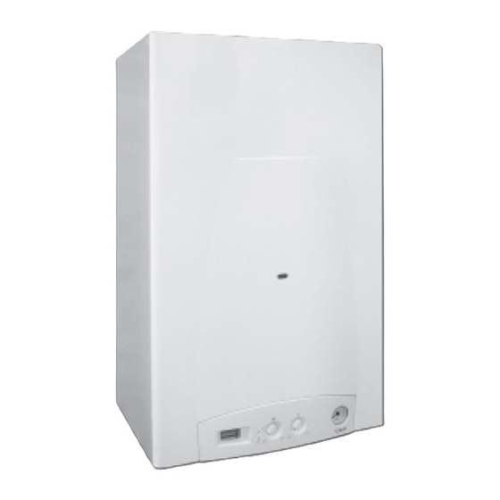
Page 7: Technical Features And Dimensions
Range of models available: • Electronic adjustment of the ignition ramp; ONLY CENTRAL HEATING PRODUCITON • Electronic frost protection mode; ALKON 28 R HE with an output of 28 kW • Pump overrun function; • Pump overrun function ALKON 35 R HE with an output of 35 kW •... -
Page 8: Main Components
Technical features and dimensions 2.3 - MAIN COMPONENTS ALKON “R” ALKON “C” 1 Condensate drain siphon 1 Condensate drain siphon 2 Aluminium heat exchanger/condenser 2 Domestic hot water temperature sensor 3 Flow temperature sensor 3 Aluminium heat exchanger/condenser 4 Overheat safety thermostat 4 Flow temperature sensor 5 Ignition/Ionisation electrode 5 Overheat safety thermostat... -
Page 9: Boiler Water Circuit
Technical features and dimensions 2.4 - BOILER WATER CIRCUITS ALKON “R” 1 DHW temperature sensor 2 Flow switch 3 Domestic hot water flow control 4 Condensate drain siphon 5 Plate heat exchanger 6 Aluminium heat exchanger/con- denser 7 Fan 8 Safety thermostat 9 Gas valve 10 Low water pressure switch 11 Return temperature sensor... -
Page 10: Performance Data
Technical features and dimensions 2.5 - PERFORMANCE DATA For information regarding the adjustment of: INJECTORS - BURNER PRESSURES – DIAPHRAGMS – OUTPUTS – GAS CONSUMPTIONS please refer to the paragraph BURNER PRESSURE ADJUSTMENT. ALKON 28 R HE 28 C HE 35 R HE 35 C HE 5,5 - 28... -
Page 11: Instructions For The Installer
Instruction for the installer INSTRUCTIONS FOR THE INSTALLER 3.1 - GENERAL WARNINGS WARNING! In rooms where aggressive vapours or dust is present the appliance must operate WARNING! independently from the air present in the This boiler has to be destined for the use for boiler’s location room! which it has been expressively designed for. -
Page 12: Standard Codes For Installation
UNICAL refuses all liability for injury to persons, animals or damage to property deriving from not having respected the above mentioned recommendations. In the packaging, in addition to the boiler, you can also find the following contents: User’s instruction guide... -
Page 13: Boiler Location
Instruction for the installer 3.4 - BOILER LOCATION When selecting the position for the installation of the boiler Ø80 please comply to the following safety requirements: • Fit the appliance in rooms protected from frost; • In rooms where aggressive vapours or dust are present, Ø100 the appliance must be able to operate independently from the air of the location room;... -
Page 14: Boiler Installation
The connection between the boiler and chimney/flue outlet can be made only after this verification has been carried out. As a safety measure against gas leaks, Unical 3.6 - GAS CONNECTION recommends installing a surveillance and... -
Page 15: Central Heating Connections
Instruction for the installer 3.7 - CENTRAL HEATING CONNECTIONS Ensure yourself that the system’s piping is WARNING! not used as earth clamps for the electrical Before installing the boiler we recommend or telephonic system. They are absolutely that the system is flushed out with a suitable unsuitable for this use. -
Page 16: Dhw Connections
Instruction for the installer 3.8 - DOMESTIC HOT WATER CONNECTIONS The pressure in the system must be between 1 (Model “C”) and 2,5 bar (if the pressure is higher fit a reducing pressure valve). WARNING! Before connecting the boiler to the water WARNING! mains supply ensure that the system is The hardness of the mains water supply... -
Page 17: Condensate Drain
Instruction for the installer 3.10 - CONDENSATE DRAIN During the combustion process the boiler produces condensate which, through the “A” pipe, flows into the siphon. The condensate which forms inside the boiler has to be routed into an adequate drain by means of the pipe “B”. DANGER! Before commissioning the appliance fill the siphon and check the correct drainage of the... -
Page 18: Water Treatment
Instruction for the installer 3.11 - WATER TREATMENT The chemical/physical features of the heating system’s water An appropriate treatment of the supply water will prevent are fundamental for the boiler’s correct operation and safety. the above stated problems and will maintain the correct operation and efficiency of the generator in time. -
Page 19: Flue Outlet Installation
The two terminals must not be fitted on to two opposite local and national Standards (refer to Standard UNI-CIG walls. 7129, point 4 and UNI-CIG point 5) We recommend using only original UNICAL flue outlet systems. Damages caused by installation errors and for non-observance of the instructions given by the same manufacturer will invalidate all the supplier’s contractual or extra contractual... - Page 20 Instruction for the installer HORIZONTAL FLUE OUTLET WITH CONCENTRIC DUCTS Ø 60/100 mm Type C13 Important: the outlet/inlet flue has to The minimum allowable length of the horizontal concentric have a minimum inclination of 3% pipes is of 0,75 metres. towards the top in the outlet direction, The maximum allowable length of the horizontal concentric so as to enable the collection of any...
- Page 21 Instruction for the installer HORIZONTAL FLUE OUTLET WITH CONCENTRIC DUCTS Ø 80/125 mm Type C13 Important: the outlet/inlet flue has to The minimum allowable length of the horizontal concentric have a minimum inclination of 3% pipes is of 0,75 metres. towards the top in the outlet direction, The maximum allowable length of the horizontal concentric so as to enable the collection of any...
- Page 22 Instruction for the installer FLUE OUTLET WITH SEPARATE DUCTS Ø 80 mm The maximum pressure loss permitted, independently from the type of installation, must not exceed the value of 100 Pa. Ø 80 TSC0130C TSC0150C KIT5780C KIT5770C 00361435 It is not permitted to position the two terminals on opposite walls.
- Page 23 5,5 Pa; - For the vertical flue outlet duct Ø 80 L=1 the pressure loss is of 8 Pa. Note: These values refer to flue systems made with original UNICAL non flexible and smooth pipes. KIT 5750C KIT 5760C...
- Page 24 10 Pa; - For the vertical flue outlet duct Ø 80 L=1 the pressure loss 00360356 is of 8 Pa Note: These values refer to flue systems made with original UNICAL non flexible and smooth pipes. 00360353 00360352 00360355...
-
Page 25: Measurement On Site Of Combustion Efficiency
“WIRING DIAGRAMS” (paragraph 3.15 pages 29) to check the appliance’s electrical system. UNICAL refuses responsibility for any damages arising from A mains supply of 230 V – 50 Hz is required. failure to earth the boiler correctly. -
Page 26: Outdoor Sensor Connection
Instruction for the installer Subsequently we have to make the maximum flow temperature Outdoor sensor connection (optional) correspond to the minimum external temperature by setting The connection of the outer sensor has to be made on the the Otc parameter (outdoor sensor set-point) terminals 5 &... -
Page 27: On-Off Digital Room Controller Connection
FREE VOLTAGE CONNECTION. DO NOT CONNECT 230V CONTROLLER. Modulating RT/OT digital room controller connection (optional) WARNING! The modulating room controllers must be supplied by Unical. DANGER! Switch off and disconnect the electricity supply before carrying out any operations on the electrical parts. -
Page 28: Layout Of The Electrical Connection For Zone Control Systems
Instruction for the installer Layout of the electrical connections for zone control systems Digital room controller External voltage line (low temperature zone controller) Room thermostat (high temperature zone controller) ON-OFF Boiler flow Low temperature zone High temperature zone Note: The terminal connections 3 and 4 in- dicated in the diagram refer to the Boiler return valve’s internal limit stop, when the... -
Page 29: Wiring Diagrams
Instruction for the installer 3.15 - WIRING DIAGRAMS FUNCTIONAL FLOW WIRING DIAGRAM ALKON R 28 HE - R 35 HE BLACK BLACK WHITE WHITE 4 BROWN(PWM) GREEN BLUE (TACHO) GREEN ORANGE LIGHT BLUE YEL/GREEN BROWN LIGHT BLUE BROWN O T T A B L A C K S R R A 1 3... -
Page 30: Alkon C
Instruction for the installer FUNCTIONAL FLOW WIRING DIAGRAM ALKON C 28 HE - C 35 HE BLACK BLACK WHITE BROWN(PWM) WHITE GREEN BLUE (TACHO) GREEN ORANGE LIGHT BLUE YEL/GREEN BROWN E.ACC./RIL. 230 V-50 Hz Note: The figures shown on the above wiring diagram are purely indicative A7...A18 = Connectors... -
Page 31: Filling The System
Use the pressure gauge fitted UNICAL refuses all liability for injury to persons, animals on the boiler to read the circuit’s pressure or damage to property deriving from not having respected value. -
Page 32: Initial Lighting
Failure to do so could cause injury to persons, animals or damage Lighting and shutting down procedures to property. UNICAL shall not be held liable for any injury and/or damage. For lighting and shutting down the boiler refer to the “USER’S ”... -
Page 33: Parameters Which Can Be Modified From Panel Board
Instruction for the installer 3.18 - PARAMETERS WHICH CAN BE MODIFIED FROM PANEL BOARD WARNING! Function reserved exclusively to the Authorized Service Centres! To enter the parameters push and keep Some of the service parameters can be modified pressed for ten seconds the reset button from the panel board: (release when the flashing wrench appe- on the display). - Page 34 Instruction for the installer Reset button with calibration function Operation at the minimum output Rotate the HEATING temperature adjustment knob “B” WARNING! between the sun and its minimum setting: Function reserved exclusively to the the boiler operates at minimum output. Authorized Service Centres! Minimum output:...
-
Page 35: Burner Pressure Adjustment
MAXIMUM OUTPUT WARNING! ADJUSTMENT SCREWS All the instructions indicated below are for the exclusive use of qualified UNICAL service technicians or installers. All the boilers leave the factory already calibrated and tested. If it is necessary to change the B) MIN OUTPUT ADJUSTMENT... - Page 36 Min CO2 >= 9% LPG: Max CO2 = 11% Min CO2 >= 10.2% Noisy flame in modulation UNICAL is not responsible for any damages caused to These adjustments can be performed only by persons, animals and goods deriving from this infringement...
-
Page 37: Variation Of Output Range
Instruction for the installer 3.20 - VARIATION OF OUTPUT RANGE With the “Regolafacile” parameter FHCH: It is possible to adjust the maximum input by reducing the fan rpm x 100 ex. 70 = 7000 rpm speed. For example: with the parameter FHCH settled on 54, the correspondent maximum input will be of 28 kW. -
Page 38: Servicing Schedule
3 mm (for example safety devices or power switches) For this reason UNICAL recommends that a servicing contract and ensure yourself that it cannot be accidentally reinser- should be made with our authorized After Sales Service ted. - Page 39 Inspections and servicing schedule Check Check every Recommended servicing operations annually 2 years Examine all water seal components for soundness Test for gas soundness Check the water and gas safety devices Clean the combustion circuit heat exchanger/body Clean the burner and check the ignition efficiency Clean the fan Check efficiency of fan’s operation Check the gas flow rate and eventual gas adjustment...
-
Page 40: Fault Codes
Codes fault FAULT CODES The symbol flashes on the display when the boiler detects a fault. 1) In case of a fault which does not causes the stop of boiler operation, to show the error code it is necessary to press the reset push button. If the boiler is in stand-by the error code appears in the display also without °C pressing the reset push button. - Page 41 Codes fault High temperature (priority 8) Description: Boiler temperature too high °C Possible solutions: Ascertain the good operation of the pump and, eventually, clean the heat exchanger Low pressure (priority 9) Description: Insufficient water pressure and, consequently, intervention of the minimum water pressure switch °C Possible solutions:...
- Page 44 - info@unical-ag.com The Unical declines every responsibility for the possible inaccuracies if owed to errors of transcript or press. Also reserves the right to bring those changes that it will hold necessary to it own products or profits, without jeopardizing its...
Need help?
Do you have a question about the ALKON 28 R HE and is the answer not in the manual?
Questions and answers