
Related Manuals for Unical ALKON 115 EXT


Summary of Contents for Unical ALKON 115 EXT
- Page 1 ALKON 115 EXT 130 EXT - 140 EXT ISTRUZIONI PER L’INSTALLATORE E IL MANUTENTORE INSTALLATION AND SERVICING MANUAL...
- Page 2 http://www.unicalag.it/prodotti/professionale-300/light-commercial-alluminio/1639/alkon-140-ext Disposizioni per uno smaltimento corretto del prodotto secondo la Direttiva 2002/96/CE Alla fine del suo ciclo di vita il prodotto non deve essere smaltito come un rifiuto urbano. Può essere portato ad un centro speciale di riciclaggio gestito dall’autorità locale, o ad un rivenditore che offre questo servizio. Lo smaltimento separato di un apparecchio domestico evita possibili conseguenze negative per l’ambiente e la salute umana derivanti da uno smaltimento improprio e permette il ricupero dei materiali di cui è...
-
Page 3: Table Of Contents
Attenzione il presente manuale contiene istruzioni ad uso esclusivo dell’installatore e/o del manutentore professionalmente qualificato, in conformità alle leggi vigenti. L’utente non è abilitato a intervenire sulla caldaia. nel caso di danni a persone, animali o cose derivanti dalla mancata osservanza delle istruzioni contenute nei manuali forniti a corredo con la caldaia, il costruttore non può... -
Page 4: Informazioni Generali
1.1 - AVVERTENZE GENERALI Il libretto d’istruzioni costituisce parte integrante ed essenziale L’eventuale riparazione dei prodotti dovrà essere effettuata solamente da personale autorizzato da unical, utilizzando del prodotto e dovrà essere conservato dall’utente. esclusivamente ricambi originali. Il mancato rispetto di quanto sopra può... -
Page 5: Simbologia Utilizzata Nel Manuale
Qualsiasi utilizzo diverso viene considerato quale improprio. Per qualsiasi danno risultante da un utilizzo improprio UNICAL AG S.p.A. non si assume alcuna respon- sabilità. Un utilizzo secondo gli scopi previsti prevede anche che ci si attenga scrupolosamente alle istruzioni del presente manuale. -
Page 6: Avvertenze Per La Sicurezza
1.5 - AVVERTENZE PER LA SICUREZZA ATTENZIONE! L’apparecchio non deve essere usato da persone con ridotte capacità fisiche, mentali e sensoriali, senza esperienza e conoscenza. Queste persone devono essere precedentemente istruite e sorvegliate durante le operazioni di manovra. I bambini devono essere sorvegliati affinchè non giochino con l’apparecchio. ATTENZIONE! L’installazione, la regolazione e la manutenzione dell’apparecchio deve essere eseguita da personale professionalmente qualificato, in conformità... -
Page 7: Targhetta Dei Dati Tecnici
1.7 - TARGHETTA DEI DATI TECNICI LegenDA: La Marcatura CE 1 = ente di sorveglianza Ce attesta la conformità dell’apparecchio ai requisiti 2 = tipo di caldaia essenziali di sicurezza definiti nelle direttive e regola- menti europei applicabili e che il suo funzionamento 3 = modello caldaia soddisfa le norme tecniche di riferimento. -
Page 8: Trattamento Dell'acqua
1.7 - TRATTAMENTO DELL’ACQUA Il trattamento delle acque di alimentazione ATTENZIONE! consente di prevenire gli inconvenienti e man- QUALSIASI DANNO PROVOCATO ALLA tenere funzionalità ed efficienza del generatore CALDAIA, DOVUTO ALLA FORMAZIONE DI nel tempo. INCROSTAZIONI O DA ACQUE CORROSIVE, NON SARà... -
Page 9: Caratteristiche Tecniche E Dimensioni
CARATTERISTICHE TECNICHE E DIMENSIONI NOTA! 2.1 - CARATTERISTICHE TECNICHE Maggiori info nella sezione ‘‘Info Tecniche’’ alla pagina della caldaia nel sito www.unicalag.it 2.2 - VISTA INTERNA CON L’INDICAZIONE DEI COMPONENTI PRINCIPALI... -
Page 10: Dimensioni
2.3 - DIMENSIONI VISTA FRONTALE VISTA LATERALE VISTA SUPERIORE VISTA DA SOTTO... - Page 11 LegenDA scambiatore/Condensatore in al- luminio n° C.e. s.e. Descrizione Valvola di sfiato sensore di temperatura acqua sani- Sifone di scarico condensa taria (n.u.) elettrodo di rilevazione flussostato con filtro acqua fredda rIL. (n.u.) elettrodo di accensione Valvola gas ACC. elettrodo di accensione/rilevazione (n.u.) rubinetto intercettazione ritorno /rIL...
-
Page 12: Diagramma Portata / Pressione Disponibile
2.4 - DIAGRAMMA PORTATA/PRESSIONE DISPONIBILE PER L’INSTALLAZIONE PreVALenzA DIsPonIBILe La tabella fornisce indicativamente le portate del circolatore in funzione del ∆t del circuito primario. ALKon 115 eXt ALKon 130 eXt ALKon 140 eXt Potenza in kW Portata massima in l/h (∆t 15 K) - Page 13 2.5 - DATI DI FUNZIONAMENTO (UNI 10348) e CARATTERISTICHE GENERALI Per i dati di regolazione: ugeLLI - PressIonI - DIAfrAmmI - PortAte fare riferimento al paragrafo ADAttAmento ALL’u- tILIzzo DI ALtrI gAs. ALKon 115 eXt ALKon 130 eXt ALKon 140 eXt...
-
Page 14: Dati Tecnici Secondo Direttive Erp
2.5.1 - DATI TECNICI SECONDO DIRETTIVA ErP ALKON Elemento Simbolo Unità Potenza utile nominale Pnominale efficienza energetica stagionale del ƞ riscaldamento d’ambiente Classe di efficienza stagionale per riscaldamento Per le caldaie per il riscaldamento d’ambiente e le caldaie miste: potenza termica utile Potenza termica utile in regime di alta temperatura 61,4... -
Page 15: Istruzioni Per L'installatore
ISTRUZIONI PER L’INSTALLAZIONE 3.1 - AVVERTENZE GENERALI ATTENZIONE! Se nel locale di installazione sono presenti ATTENZIONE! polveri e/o vapori aggressivi/corrosivi, Questa caldaia deve essere destinata solo l’apparecchio deve essere adeguatamente all’uso per il quale è stata espressamente protetto e deve poter funzionare prevista. -
Page 16: Imballo
- Sonda esterna - Sifone (*) sopra esposto. (*) - Per installazioni esterne ordinare il kit antigelo (sifone) non fornito a corredo della caldaia. ALKON 115 EXT - 130 EXT - 140 EXT Peso Peso profondità larghezza altezza... -
Page 17: Posizionamento In Centrale Termica
3.5 - POSIZIONAMENTO IN CENTRALE TERMICA Particolare importanza deve essere data alle norme e leggi lo- cali in fatto di centrali termiche ed in special modo alle distanze minime che devono essere mantenute libere intorno alla caldaia. L’installazione deve essere conforme alle prescrizioni contenu- te nelle più... -
Page 18: Allacciamento Condotto Scarico Fumi
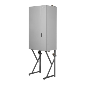
3.6 - ALLACCIAMENTO CONDOTTO TELAIO DI SUPPORTO SCARICO FUMI Per l’allacciamento del condotto scarico fumi sono da rispettare le normative locali e nazionali nel caso di sostituzione di caldaie, sostituire semPre anche il condotto fumi. La caldaia è omologata per la configurazione di scarico sotto- riportate B23P LungHezzA totALe ( Lscarico) - Page 19 Adattatori Ø 120 opzionali per sistemi sdoppiati...
-
Page 20: Allacciamento
3.7 - ALLACCIAMENTO Scarico condensa La caldaia, durante il processo di combustione, produce con- 1’’ densa che, attraverso il tubo “A”, fluisce nel sifone. La condensa che si forma all’interno della caldaia deve essere Pericolo! L’allacciamento del gas deve essere eseguito fatta fluire in uno scarico adeguato tramite il tubo “B”. -
Page 21: Riempimento Dell'impianto
Può danneggiare le guarnizioni e provocare l’insorgere di rumori durante il funzionamento. La Unical declina ogni responsabilità nel caso danni procurati a persone, animali o cose su- bentranti in seguito a mancata osservanza di quanto sopra esposto. -
Page 22: Allacciamenti Elettrici
3.9 - ALLACCIAMENTI ELETTRICI LegenDA fusibile Alimentazione 6,3 A n° Descrizione fusibile Alimentazione 6,3 A Int C1 Interruttore Inibizione Corpo 1 Bmm 1 scheda gestione bruciatore corpo 1 Int C2 Interruttore Inibizione Corpo 2 Bmm 2 scheda gestione bruciatore corpo 2 PPD1 Predisposizione pressost. - Page 23 Pericolo! sempre l’alimentazione elettrica e assicurarsi che non possa L’installazione elettrica deve essere eseguita essere accidentalmente reinserita. solo a cura di un tecnico abilitato. Prima di eseguire i collegamenti o qualsiasi operazione sulle parti elettriche, disinserire Collegamento sonda esterna Collegamento sicurezze INAIL (*) Collegamento Sicurezze Predisposto sulla morsettiera, BCm...
- Page 24 Pannello comandi in remoto NOTA! Maggiori info nella sezione ‘‘Info Tecniche’’ alla pagina della caldaia nel sito www.unicalag.it...
-
Page 25: Prima Accensione
Prima della messa in funzione della caldaia è opportuno veri- da personale professionalmente qualificato. La ficare quanto segue: unical declina ogni responsabilità nel caso danni procurati a persone, animali o cose, subentranti in seguito a mancata osservanza di quanto sopra esposto. -
Page 26: Misura In Opera Rendimento Di Combustione
3.11 - MISURA IN OPERA DEL RENDIMENTO DI COMBUSTIONE 3.11.1- ATTIVAZIONE DELLA FUNZIONE DI TARATURA ATTENZIONE! MASSIMA/MINIMA POTENZA Funzione riservata esclusivamente ai Centri di Assistenza Autorizzati. Posizionarsi con manopola ‘‘C’’ su SELEZIONE Confermare con il tasto ‘‘A’’ viene visualizzato Posizionarsi con manopola ‘‘C’’ su Confermare con il tasto ‘‘A’’... -
Page 27: Posizionamento Sonde
3.11.2 - POSIZIONAMENTO DELLE SONDE Per determinare il rendimento di combustione occorre effettuare le seguenti misurazioni: AttenzIone! - misura della temperatura aria comburente rimuovere - misura della temperatura fumi e del tenore della Co prele- il tappo 2, vata nell’apposito foro 2. Inserire effettuare le specifiche misurazioni con il generatore a regime la sonda... - Page 28 3) Conclusione delle tarature di base - controllati i valori della Co alla minima e massima portata - richiudere le prese ispezione fumi del terminale di aspirazione ed eseguiti se necessario eventuali ritocchi (punti 1-2): e scarico - disattivare la funzione “taratura” temporizzata togliendo - verificare che non vi siano perdite di gas.
-
Page 29: Ispezione E Manutenzione
• Aprire la mandata ed il ritorno del riscaldamento nonché la ginali unical. valvola di entrata dell’acqua fredda (se chiuse in preceden- za). Qualora si renda necessaria la sostituzione di un componente: •... - Page 30 1) eseguire misurazione Portata termica trami- si consiglia di utilizzare i prodotti appo- te contatore e confrontare il valore ottenuto con sitamente creati da unical (vedi listino domestico sez. ACCessorI di prote- quello riportato in tabella 3.12. Il dato rilevato zione impianti), usando l’accortezza di...
-
Page 31: Adattamento All'utilizzo Di Altri Gas
4.3 - ADATTAMENTO ALL’UTILIZZO DI ALTRI GAS Le caldaie sono prodotte per il tipo di gas specificatamente Trasformazione Gas richiesto in fase di ordinazione. NOTA! Maggiori info nella sezione PERICOLO ! ‘‘Info Tecniche’’ alla pagina della La trasformazione per il funzionamento della caldaia nel sito www.unicalag.it caldaia con un tipo di gas diverso da quello specificatamente richiesto in fase di ordina-... -
Page 32: Programmazione Parametri Di Funzionamento
4.4 - PROGRAMMAZIONE DEI PARAMETRI DI FUNZIONAMENTO ATTENZIONE! SELEZIONE Gestione dispositivi Funzione riservata esclusivamente ai Centri di Assistenza Autorizzati. con manopola ‘‘C’’ e premere il tasto ‘‘A’’, selezionare per accedere alla programmazione tecnica di ogni dispositi- vo (è richiesta password 0000). SELEZIONE SELEZIONE selezionare con manopola ‘‘C’’... - Page 33 PARAMETRI MODULO BMM CODICE SIMBOLO DESCRIZIONE PARAMETRO U.M. RANGE IMPOSTAZIONI FABBRICA servizi Abilitati CH # 1: setpoint minimo °C CH # 1: setpoint massimo °C Pompa: Post circolazione Pompa: Comando minimo Pompa: Comando massimo relay Programmabile #1 ACs: Abilita il sens. di richiesta ACs: setpoint minimo °C ACs: setpoint max.
- Page 34 PARAMETRI HCM (bCM) CODICE SIMBOLO DESCRIZIONE PARAMETRO U.M. RANGE IMPOSTAZIONI FABBRICA servizi Abilitati CH: temp. Differenziale max °C 50,0 30,0 Isteresi del Bruciatore °C 20,0 CH: setpoint minimo °C 20,0 40,0 25,0 CH: setpoint massimo °C 45,0 85,0 85,0 sensore temp. esterna Pompa: Postcircolazione Pompa: Comando minimo Volt...
-
Page 36: Schema Elettrico
4.5 - SCHEMA ELETTRICO DI COLLEGAMENTO PRATICO... - Page 37 VIoLA A1...A9 = Connettori servizi = Alimentazione pompa set PoInt emergenCY = temperatura di set point quando la caldaia modulante é in emergenza. (*) Valore di resistenza = Controllo pompa modulante = Pressostato sicurezza contro C.P.m.g = modulazione Pompa modulante la mancanza acqua (generale o di Impianto) e.
-
Page 38: Codici Di Errore
4.6 - CODICI DI ERRORE Quando la caldaia rileva una anomalia, ll simbolo allarme Il ripristino della caldaia è possibile premendo il viene visualizzato sul display, con il relativo codice di errore e tasto ‘‘A’’. la descrizione. ( Num ) = vedi legenda Par. 2.2 CoDICe DesCrIzIone rImeDI... - Page 39 VELOCITA’ FUORI Verificare il funzionamento del ventilatore (18) e le connessioni CONTROLLO Alterazione della velocità ventilatore la velocità non viene raggiunta. VELOCITA’ FUORI Verificare il funzionamento del ventilatore (18) e le connessioni CONTROLLO Alterazione della velocità ventilatore la velocità e’ superiore a quella richiesta SCARICHI OSTRUITI Verificare Camini / Verificare sifone.
- Page 40 http://www.unicalag.it/prodotti/professionale-300/light-commercial-alluminio/1639/alkon-140-ext Provisions for proper disposal of the product in accordance with Directive 2002/96/EC At the end of its life cycle the product must not be disposed of as urban waste. It can be taken to a special recycling centre managed by the local authorities, or to a dealer who offers this service. Separate disposal of a domestic appliance avoids possible negative consequences for the environment and human health deriving from inappropriate waste handling and allows the recovery of the materials of which it is made, in order to obtain significant energy and resource savings.
- Page 41 Attention: this manual contains instructions for the exclusive use of the professionally qualified installer and/or maintenance technician in compliance with current legislation. The user is NOT qualified to intervene on the boiler. The manufacturer will not be held liable in case of damage to persons, animals or objects resulting from failure to comply with the instructions contained in the manuals supplied with the boiler.
-
Page 42: General Information
Any repairs must be performed solely by personnel authorised by Unical AG S.p.A., using original spare parts only. Failure to product and must be kept by the user. comply with the above can compromise the safety of the appli- ance and void the warranty. -
Page 43: Symbols Used In The Manual
Any other use is considered improper. For any damage resulting from improper use UNICAL AG. s.p.A. assumes no responsibility. Use according to the intended purposes also includes strict compliance with the instructions in this manual. 1.4 - INFORMATION PROvIDED TO THE UsER The user must be instructed concerning the use and operation of his heating system, in particular: •... -
Page 44: Safety Warnings
1.5 - sAFETY wARNINGs ATTENTION! The boiler must not be used by people with with reduced physical, sensory and mental abilities, without experience and knowledge. These people must be previously trained and supervised during the manoeuvre operations. Children must be supervised so that they do not have access to the boiler. ATTENTION! The appliance must be installed, adjusted and maintained by professionally qualified personnel, in com- pliance with the standards and provisions in force. -
Page 45: Technical Data Plate
1.6 - TECHNICAL DATA PLATE The CE marking KEY: 1 = CE monitoring body certifies the compliance of the equipment with the 2 = Type of boiler essential safety requirements defined in the directi- 3 = Boiler model ves and applicable European regulations and that 4 = Number of stars (directive 92/42 EEC) its functioning satisfy applicable technical stan- 5 = (S.N°) Serial Number... -
Page 46: Water Treatment
1.7 - wATER TREATMENT The treatment of the supply water allows to ATTENTION! prevent inconveniences and maintain the ANY DAMAGE TO THE BOILER CAUsED BY functionality and efficiency of the generator THE FORMATION OF FOULING OR BY COR- over time. ROsIvE wATER wILL NOT BE COvERED BY THE wARRANTY. -
Page 47: Technical Features And Dimensions
TECHNICAL FEATUREs AND DIMENsIONs NOTE! 2.1 - TECHNICAL FEATUREs Further details in the section ‘‘Technical Information’’ on the boiler page of the www.unicalag.it website 2.2 - vIEw wITH THE INDICATION OF THE MAIN COMPONENTs... -
Page 48: Dimension
2.3 - DIMENsIONs Front view side view view from above view from below... - Page 49 Aluminium Heat Exchanger/ Capacitor Description N° C.E. S.E. Vent valve Domestic hot water temperature Condensation drain trap sensor (N.U.) Detection electrode Flow switch with cold water filter RIL. (N.U.) Ignition electrode Gas valve ACC. Ignition/detection electrode (N.U.) Return shut-off valve /RIL Sensor Flow General Burner...
- Page 50 Flow rate (l/h) The table provides an indication the flow the pump in function of the Dt of the primary circuit. ALKON 100 EXT ALKON 115 EXT ALKON 140 EXT Power supply in kW Max flow rate demanded l/h (Dt 15 K)
- Page 51 2.5 - OPERATING DATA ACCORDING TO UNI 10348 and GENERAL FEATUREs For the adjustment data: NOZZLES - PRESSURE - DIAGRAMS - FLOW RATES - CONSUMPTION refer to the paragraph ADAP- TATION TO OTHER TYPES OF GAS. ALKON 100 EXT ALKON 115 EXT ALKON 140 EXT Appliance category 2H3P...
-
Page 52: Data Erp Directive
2.5.1 - DATA ACCORDING TO ErP DIRECTIvE ALKON Description symbol Unit Nominal Heat Output Pnominale Seasonal space heating energy ƞ efficiency Seasonal efficiency class in heating mode For CH only and combination boilers: useful heat output Useful Heat Output in high-tempera- ture regime 55,0 61,4... -
Page 53: Installation Instructions
INsTALLATION INsTRUCTIONs 3.1 - GENERAL wARNINGs ATTENTION! ATTENTION! If there is dust and/or if there are his boiler is intended solely for the use for aggressive/corrosive vapours present in which it was expressly designed. Any other the installation room, the appliance must use is to be considered improper and there- be protected suitably and must be able to fore dangerous. -
Page 54: Packaging
- Air inlet filter. danger. Unical AG s.p.A. will not be held liable for damage - Kit multifunction module SHC to persons, animals or objects due to failure to - Outdoor sensor comply with the instruction above. - Page 55 3.5 - POsITIONING IN BOILER ROOM Particular importance should be given to local regulations and laws in terms of boiler room and especially the minimum distance that must be kept clear around the boiler. The installation must conform to the requirements contained in the most recent regulations and laws in terms of boiler room, installations of heating and production of hot water, ventilation, chimneys suitable to discharge the products of combustion of...
-
Page 56: Flue Gas Exhaust Pipe Connection
3.6 - FLUE GAs EXHAUsT PIPE SUPPORT FRAME (2) optional CONNECTION To connect the flue gas exhaust pipe, local and national stand- ards must be observed In the event the boiler is replaced, ALWAYS replace the flue gas pipe as well. The boiler is type approved for the exhaust configurations listed below: B23P... - Page 57 Ø 120 optional adapters for twin flue systems...
-
Page 58: Connections
3.7 - CONNECTION Condensation drain The boiler, during the combustion process, produces conden- 1’’ sation that, through pipe “A”, flows into the trap. The condensation that forms inside the boiler flows into a suitable Danger! drain via pipe “B”. The gas connection must be carried out only by Danger! a qualified installer who must respect and apply Before commissioning the appliance:... -
Page 59: Filling The System
This could damage the gaskets and cause noise during operation. Unical will not be held liable for damage to persons, animals or objects due to failure to comply with the above instruction. Pressure in the mains supply must be between 0.5... -
Page 60: Electrical Connections
3.9 - ELECTRICAL CONNECTIONs Power Fuse 6,3 A N° Descption Power Fuse 6,3 A INT C1 Switch Inhibit Body 1 BMM 1 Burner modul manager body 1 INT C2 Switch Inhibit Body 2 BMM 2 Burner modul manager body 2 PPD1 Connection pressure switch 1 optional Power supply terminal 230 V... - Page 61 Danger! connect electrical power and make sure that it cannot be Only a qualified technician may perform the reconnected accidentally. electrical installation. Before performing connections or any type of operation on electrical parts, always dis- Outer sensor connection safety connection (*) safety Conection connect the wires on therminal,...
- Page 62 Control panel remotely NOTE! For more information see Technical Info from site indicated at pag. 2...
-
Page 63: Commissioning
3.10 - COMMIssIONING Commissioning must be done by professionally instruction. qualified personnel. Unical AG S.p.A. will not be Before commissioning the boiler, check that: held liable for damage to persons, animals or objects due to failure to comply with the above... -
Page 64: Measurement Of Combustion Efficiency During Installation
3.11 - MEAsUREMENT OF COMBUsTION EFFICIENCY DURING INsTALLATION 3.11.1- ACTIvATION OF THE CALIBRATION FUNCTION ATTENTION! MAXIMUM / MINIMUM POwER Function reserved for Authorised Assistance Centres only. Place with knob ‘‘C’’ on sELECTION Confirm with button ‘‘A’’ display shows Place with knob ‘‘C’’ on Confirm with button ‘‘A’’... - Page 65 3.11.2 - POsITIONING THE PROBEs To determine the combustion efficiency one must make the following measurements: ATTENTION! - measurement of the combustion air temperature Remove - measurement of the flue gas temperature and content of cap 2, taken in the relevant hole 2. Insert Take the measurements with the generator in steady state the CO2 probe...
- Page 66 Start-up Press. Nozzles diaphragm power. [mbar] (mm) [Ø/n.holes] FL [% FU] FH [% FU] Nat gas (G20) Nat gas (G25) Propane (G31) ALKON 115 EXT Type of Supply Ø Collector Fan speed levels Start-up Press. Nozzles diaphragm power. [mbar] (mm) [Ø/n.holes]...
-
Page 67: Inspection And Maintenance Instructions
4.1 - INsPECTION AND MAINTENANCE INsTRUCTIONs To assure long-term functioning of your appliance and to avoid Once all maintenance operations are complete altering its approved status, only original Unical spare parts resume boiler operation. must be used. • Open the heating flow and return pipes, as well as the cold water inlet valve (if closed previously). - Page 68 1) Measure the Thermal Capacity using a me- It is recommended to use the products ter and compare the value with that contained purposely created by Unical (see sys- tem protection ACCESSORIES sect. in in table 3.12. The data measured indicates if the domestic price list), being careful the exchanger needs cleaning.
-
Page 69: Adaptation To The Use Of Other Gas
4.3 - ADAPTATION TO THE UsE OF OTHER GAs The boilers are produced for the type of gas specifically requested Gas Conversion upon ordering. NOTE! For more information DANGER! see Technical Info The conversion for the operation of the boiler from site indicated at pag. -
Page 70: Operation Parameters Programming
4.4 - OPERATION PARAMETER PROGRAMMING ATTENTION! sELECTION DEvICE sETTING Function reserved for Authorised Assistance Centres only. with knob ‘‘C’’ and push buton ‘‘A’’, to enter Selection in programming list for each device (requires password 0000). sELECTION sELECTION With knob ‘‘C’’ select simbol . - Page 71 PARAMETER BMM MODULE CODE SYMBOL PARAMETER DESCRIPTION U.M. RANGE SETTING FACTORY Enabled services CH # 1: Minimum value of the CH setpoint °C adjustment Maximum value of the CH setpoint adjust- °C ment Pump overrun time Pump minimum modulation level Pump maximum modulation level Relay Programmabile #1 Enable the DHW request by the tempera- ture sensor...
- Page 72 PARAMETER HCM (BCM) MODULE CODE SYMBOL PARAMETER DESCRIPTION U.M. RANGE SETTING FACTORY Enabled services CH: Temp. Differenziale Max °C 50,0 30,0 Burner OFF hysteresis °C 20,0 CH: Setpoint min °C 20,0 40,0 25,0 CH: Setpoint max °C 45,0 85,0 85,0 Sensore Temp. Esterna Pump overrun time Pump minimum modulation level Volt...
-
Page 74: Wiring Diagram
4.5 - wIRING DIAGRAM... - Page 75 = Services Connector A1...A9 = Supply Modulating Pump = Modulating pump control SET POINT EMERGENCY = Set point temperature when the boiler is in emergency. = Safety low water pressure switch (*) (Resistor value) E. ACC. = Ignition electrode E. RIL. = Detection Electrode C.P.M.G = Modulation Pump Control = Insert BCM...
- Page 76 4.6 - ERROR CODE Reset is possible by pressing ''A'' button. When the boiler detects an error, fault symbol appears on the display, with the corresponding error code and description. ( Num ) = see key Par. 2.2 SYMBOL DESCRIPTION OF FAULT SOLUTION DETECTED ON BMM sAFETY THERMOsTAT...
- Page 77 sPEED OUT OF Check fan operation (18) and the connections CONTROL Alteration of the fan speed; the speed is above that requested OBsTRUCTION EXHAUsT Check Chimney / Ceck siphon FACTORY PARAMETERs Press the unblock key; if the anomaly persists, replace the board. Alteration of the factory parameters due to possible electromagnetic interferences.
- Page 80 - export@unical-ag.com - www.unical.eu Unical declina ogni responsabilità per le possibili inesattezze se dovute ad errori di trascrizione o di stampa. Si riserva altresì il diritto di apportare ai propri prodotti quelle modifiche che riterrà necessarie o utili, senza pregiudicarne le caratteristiche essenziali.
Need help?
Do you have a question about the ALKON 115 EXT and is the answer not in the manual?
Questions and answers