Table of Contents
Advertisement
Quick Links
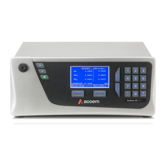
Serinus® 40
Oxides of Nitrogen
ACOEM Ecotech
1492 Ferntree Gully Road Knoxfield VIC 3180
Melbourne Australia +61 3 9730 7800 info.au@acoem.com ecotech.com
Manual subject to change without notice. Images used are for illustrative purposes only. Ecotech & Serinus are trademarks or registered trademarks
of Ecotech Pty Ltd in the United States and/or other countries. © 2021 Ecotech Pty Ltd. All Rights Reserved.
Analyser
User Manual
Version: 3.5
Advertisement
Table of Contents
Troubleshooting

Related Manuals for ACOEM Serinus 40


Summary of Contents for ACOEM Serinus 40
- Page 1 ACOEM Ecotech 1492 Ferntree Gully Road Knoxfield VIC 3180 Melbourne Australia +61 3 9730 7800 info.au@acoem.com ecotech.com Manual subject to change without notice. Images used are for illustrative purposes only. Ecotech & Serinus are trademarks or registered trademarks of Ecotech Pty Ltd in the United States and/or other countries. © 2021 Ecotech Pty Ltd. All Rights Reserved.
- Page 2 Ser in u s ® 40 U ser M an u al 3 .5 This page is intentionally blank. Page 2...
-
Page 3: Table Of Contents
Table of Contents Manufacturer’s Statement ............................ 13 Notice ..................................13 Safety Information ..............................14 Important Safety Messages ........................... 15 Warranty ................................16 Service & Repairs ..............................17 Product Compliance and Approvals ........................18 Manual Revision History ............................19 Introduction ........................... 21 Description .............................. - Page 4 Ser in u s ® 40 U ser M an u al 3 .5 EN Type Approval Set-up .......................... 48 Transporting/Storage ..........................48 Operation ..........................51 Warm-Up ..............................51 Measurement ............................51 General Operation Information ........................ 52 3.3.1 Keypad & Display........................52 3.3.2 Home Screen ..........................
- Page 5 4.3.3 Port Forwarding on Remote Modem/Router Setup ..............101 4.3.4 Setup Airodis to Communicate with Serinus ................101 Analog and Digital Communication ......................102 4.4.1 Analog Outputs ........................102 4.4.2 Analog Inputs ........................... 103 4.4.3 Digital Status Inputs ......................... 103 4.4.4 Digital Status Outputs ......................
- Page 6 Ser in u s ® 40 U ser M an u al 3 .5 Maintenance Procedures ........................146 6.4.1 Particulate Filter Replacement ....................146 6.4.2 Clean Chassis Fan Filter ......................148 6.4.3 DFU Replacement ........................149 6.4.4 Leak Check ..........................149 6.4.5 Clean Pneumatics ........................
- Page 7 8.11.1 Trace Specifications ......................... 194 8.11.2 Trace Setup ..........................195 8.11.3 Trace Operation ........................196 8.11.4 Trace Default Values ........................ 196 8.11.5 Trace Calibration Guidelines ....................197 8.11.6 Trace Service and Maintenance ....................198 Parts List and Schematics ....................199 Serinus Accessories Kit ..........................
- Page 8 Ser in u s ® 40 U ser M an u al 3 .5 List of Figures Figure 1 – Simple Pneumatic Diagram .......................... 26 Figure 2 – Major Components of Serinus 40 ........................ 27 Figure 3 – Calibration Valve Manifold .......................... 28 Figure 4 – Auxiliary Valve Manifold ..........................28 Figure 5 –...
- Page 9 Figure 51 – Digital Pots Menu Screen .......................... 73 Figure 52 – Internal Pump Menu Screen ........................74 Figure 53 – Valve Menu Screen ............................ 75 Figure 54 – Tests Menu Screen ............................ 77 Figure 55 – Digital Input Test Menu Screen ......................... 77 Figure 56 –...
- Page 10 Ser in u s ® 40 U ser M an u al 3 .5 Figure 103 – Logs Format ............................120 Figure 104 – Colour Theme Settings ........................... 121 Figure 105 – Example of a Calibration System ......................123 Figure 106 – Full Pressure Calibration Set-up ......................126 Figure 107 –...
- Page 11 Figure 155 – Attach Rack Mount Adaptors to Outer Slides ..................181 Figure 156 – Test Fit the Rack Slide Assembly into Your Rack..................182 Figure 157 – Attach Slides to Front of Rack ....................... 182 Figure 158 – Slide Clips .............................. 183 Figure 159 –...
- Page 12 Ser in u s ® 40 U ser M an u al 3 .5 Table 41 – Spare Part List (High Level Instrument) ..................... 207 Table 42 – Spare Part List (IZS) ........................... 207 Table 43 – Spare Part List (Trace Level Instrument) ....................207 Table 44 –...
-
Page 13: Manufacturer's Statement
Thank you for selecting the Ecotech Serinus® 40 Oxides of Nitrogen Analyser. The Serinus series is the next generation of Ecotech designed and manufactured gas analysers. The Serinus 40 will perform NO, NO and NO measurements over a range of 0 - 20 ppm with a lower detectable limit of 0.4 ppb. -
Page 14: Safety Information
Ser in u s ® 40 U ser M an u al 3 .5 Safety Information Read all the safety information in this section prior to using the equipment. To reduce the risk of personal injury caused by potential hazards, follow all safety notices and warnings in this documentation. -
Page 15: Important Safety Messages
Important Safety Messages Disconnect Power Prior to Service Hazardous voltages exist within the instrument. Do not remove or modify any of the internal components or electrical connections whilst the mains power is ON. Always unplug the equipment prior to removing or replacing any components. Replacing Parts Replacement of any part should only be carried out by qualified personnel, using only parts specified by Ecotech, as these parts meet stringent Ecotech quality. -
Page 16: Warranty
Ser in u s ® 40 U ser M an u al 3 .5 Warranty This product has been manufactured in an ISO 9001 facility with care and attention to quality. The product is subject to a 24-month warranty on parts and labour from date of shipment. The warranty period commences when the product is shipped from the factory. -
Page 17: Service & Repairs
Service & Repairs Our qualified and experienced technicians are available to provide fast and friendly service between the hours of 8:30 am – 5:00 pm AEST Monday to Friday. Please contact either your local distributor or Ecotech regarding any questions you have about your instrument. Service Guidelines This manual is designed to provide the necessary information for the setup, operation, testing, maintenance and troubleshooting of your instrument. -
Page 18: Product Compliance And Approvals
Ser in u s ® 40 U ser M an u al 3 .5 Product Compliance and Approvals The Serinus® 40 Oxides of Nitrogen Analyser, as manufactured by Ecotech Pty Ltd, complies with the essential requirements of the directives listed below (including CE compliance). The respective standards have been applied: Low Voltage Directive (LVD) Directive 2014/35/EU EN 61010-1:2010... -
Page 19: Manual Revision History
Manual Revision History Manual PN: M010028 Current revision: Date released: 2 December 2021 Description: User Manual for the Serinus® 40 Oxides of Nitrogen Analyser This manual is the full user manual for the Serinus® 40 Oxides of Nitrogen Analyser. This manual contains all relevant information on theory, specifications, installation, operation, maintenance and calibration. - Page 20 Ser in u s ® 40 U ser M an u al 3 .5 January 2011 High level option added Updates to power specifications/battery Updates to serial communications Updated maintenance kit September 2011 Analog inputs Network adapter menu General overhaul of manual drawings, pictures and content July 2012 New chassis...
-
Page 21: Introduction
) with a range of 0 - 20 ppm. The U.S. EPA has designated the Serinus 40 Oxides of Nitrogen Analyser as a reference method and TÜV has designated it as an EN approved instrument. This section will describe the specifications of the instrument as well as the main components and techniques used to obtain stable gas concentration readings. -
Page 22: Calibration
Ser in u s ® 40 U ser M an u al 3 .5 1.2.3 Calibration Zero Drift Temperature dependant: 0.1 ppb per °C 24 hours: < 0.5 ppb 7 days: < 0.5 ppb Span Drift Temperature dependant: 0.1% per °C 7 days: <... -
Page 23: Physical Dimensions
Current output of 0 - 20 mA, 2 - 20 mA or 4 - 20 mA. Voltage output of 0 - 5 V, with menu selectable zero offset of 0 V, 0.25 V or 0.5 V. Voltage output of 0 - 10 V (configured using jumpers (JP3) on rear panel PCA). ... -
Page 24: Nomenclature
Ser in u s ® 40 U ser M an u al 3 .5 Chinese Pattern Approval (JJF1361-2012) 1.3 Nomenclature This is the abbreviation of nitrogen oxide or nitric oxide. This is the abbreviation of nitrogen dioxide. A generic term for mono-nitrogen oxides NO and NO A gas sample of known composition and concentration used to Span calibrate/check the response of the instrument. -
Page 25: Background/Theory
Bootloader A program that checks whether the current firmware is valid, executes the instrument start-up. The bootloader can be entered by pressing the ‘+’ key on the front keypad during the first ½ second after power ON and following the prompts. The bootloader enables various low level recovery tools, including updating the firmware from a USB memory stick. -
Page 26: Figure 1 - Simple Pneumatic Diagram
Ser in u s ® 40 U ser M an u al 3 .5 As the activated species NO * reverts to a lower energy state, it emits broad-band radiation from 500 - 3000 nm, with a maximum intensity at approximately 1100 nm. Since one NO molecule is required to form one NO * molecule, the intensity of the Chemiluminescent reaction is directly proportional to the NO concentration within the sample. -
Page 27: Kalman Filter Theory
When the signal is steady, a long integration time is used to reduce noise. The system continuously analyses the signal and uses the appropriate filtering time. 1.5 Instrument Description The major components of the Serinus 40 are described below: Figure 2 – Major Components of Serinus 40 Introduction... -
Page 28: Calibration Valve Manifold
Ser in u s ® 40 U ser M an u al 3 .5 1.5.1 Calibration Valve Manifold Refer to Figure 2 for the location of calibration valve manifold. The calibration valve manifold switches between sample, calibration and internal zero. Figure 3 –... -
Page 29: Dryer
all particles larger than 5 µm from entering the measurement system that could interfere with sample measurement. Note: The 5-micron filter element should be replaced on a regular basis. Figure 5 – Sample Filter Holder 1.5.5 Dryer Refer to Figure 2 for the location of dryer. The dryer is constructed of Nafion tubing and is designed to remove water vapour from ambient air that is used by the Ozone generator. -
Page 30: Ozone Generator
Ser in u s ® 40 U ser M an u al 3 .5 1.5.6 Ozone Generator Refer to Figure 2 for the location of Ozone generator. The Ozone generator is a corona discharge Ozone source driven by an ignition coil. Dry air is drawn into the discharge tube via an orifice and ionised by a high voltage electrode. -
Page 31: Measurement Cell
1.5.8 Measurement Cell Figure 9 – Measurement Cell 1.5.8.1 PMT Assembly Figure 10 – PMT Assembly Photomultiplier Tube (PMT) Refer to Figure 10 for the location of PMT. The PMT detects the amount of light reaching its sensors. The selective filtering of light reaching the PMT allows for direct measurement of NO reacting with O in the reaction cell. -
Page 32: Figure 11 - Reaction Cell
Ser in u s ® 40 U ser M an u al 3 .5 Magnetic Shield Refer to Figure 10 for the location of magnetic shield. The magnetic shield is used to protect PMT from electromagnetic radiation. Which will reduce the amount of noise generated in the PMT. 1.5.8.2 Reaction Cell Refer to Figure 9 for the location of reaction cell. -
Page 33: Pneumatic Tubing
Pressure Sensor PCA Refer to Figure 11 for the location of pressure sensor PCA. The pressure sensor PCA has an absolute- pressure transducer that is mounted on the reaction cell and sealed via a gasket. This allows the pressure sensor PCA to measure the sample air pressure in the reaction cell. This pressure reading is used to verify sample flow and correct measurement readings for pressure variations. -
Page 34: Rear Panel
Refer to Figure 15 for the location of chassis fan. The chassis fan is assembled to the back side of the instrument to maintain the Serinus 40 temperature. Fan filter is also installed with the fan to prevent the instrument from dust. -
Page 35: Communications
ON/OFF Switch The ON/OFF switch is located on the rear panel (bottom right facing the rear of the instrument), refer to Figure 16. It is part of the power supply. Figure 16 – Power ON/OFF Switch 1.5.12 Communications Communication between the instrument and either a data logger, laptop or network can be performed with the following communication connections located on the rear panel (refer to Figure 23). - Page 36 Ser in u s ® 40 U ser M an u al 3 .5 Analog & Digital I/O The analog/digital port sends and receives analog/digital signals to other devices. These signals are commonly used to activate gas calibrators or for warning alarms. Analog Outputs The instrument is equipped with three user definable analog outputs.
-
Page 37: Installation
2.1 Initial Check Packaging The Serinus 40 is transported in packaging which is specifically designed to minimise the effects of shock and vibration during transportation. Ecotech recommends that the packaging be kept if there is a likelihood that the instrument is going to be relocated. -
Page 38: Figure 18 - Received Item
Ser in u s ® 40 U ser M an u al 3 .5 Figure 18 – Received Item Page 38... -
Page 39: Figure 19 - Opening The Instrument - 1
Opening the Instrument Check the interior of the instrument with the following steps: 1. Refer to Figure 19. Remove the thumb screws located on the rear panel. Figure 19 – Opening the Instrument – 1 2. Refer to Figure 20. Unlocked the slam lock using keys provided with instrument. Figure 20 –... -
Page 40: Installation Notes
Ser in u s ® 40 U ser M an u al 3 .5 4. Refer to Figure 22. To completely remove the lid, slide the lid backwards until the rollers line up with the gaps in the track and lift the lid upwards to remove from the instrument. Figure 22 –... -
Page 41: Instrument Set-Up
2.3 Instrument Set-Up After installing the instrument the following procedures should be followed to ready the instrument for monitoring: Figure 23 – Instrument Rear Panel 2.3.1 Power Connections CAUTION Hazardous voltages exist within the instrument. Do not remove or modify any of the internal components or electrical connections whilst the mains power is ON. -
Page 42: Pneumatic Connections
2.3.2 Pneumatic Connections The Serinus 40 has four pneumatic ports on the rear panel of the instrument: the Sample Port, the Calibration Port, the Exhaust Port and the Background Air Port. All tubing and fittings used should follow the instructions below: ... -
Page 43: Figure 26 - Dust Plugs
Procedure 1. Refer to Figure 26. Remove all the dust plugs. Figure 26 – Dust Plugs 2. Refer to Figure 27. Remove the sample port nut. Figure 27 – Remove Nut 3. Refer to Figure 28. Inspect the ferrules inside the nut for correct orientation. Figure 28 –... -
Page 44: Figure 29 - Replace Nut Loosely
Ser in u s ® 40 U ser M an u al 3 .5 4. Refer to Figure 29. Replace the nut loosely, only 2 or 3 threads, on the sample port. Figure 29 – Replace Nut Loosely 5. Refer to Figure 30. Push the tubing into the end of the nut until you hit the tube stop inside the fitting. -
Page 45: Communications Connections
The exhaust port should be connected to the vacuum pump using ¼” OD tubing. The P030004, 240 V vacuum pump (P030005, 110 V) available from Ecotech, should be used to provide the required vacuum and flow for one Serinus 40 analyser. CAUTION Oxides of nitrogen are toxic gases. -
Page 46: Instrument Set-Up
Ser in u s ® 40 U ser M an u al 3 .5 2.3.4 Instrument Set-Up 1. Refer to Figure 32. Open the lid and make sure the USB memory stick is installed. Figure 32 – Installation of USB Memory Stick 2. -
Page 47: Epa Reference Set-Up
2.4 U.S. EPA Reference Set-Up The Serinus 40 is designated as reference method RFNA–0809–186 by the U.S. EPA (40 CFR Part 53). The Serinus 40 must be used under the following conditions to satisfy this approval: Range 0 - 0.050 ppm and 0 - 1.0 ppm Ambient Temperature 20 - 30 °C... -
Page 48: Type Approval Set-Up
Ser in u s ® 40 U ser M an u al 3 .5 2.5 EN Type Approval Set-up The Serinus 40 has been certified to TÜV performance standards for Continuous Ambient Air Quality Monitoring Systems. The certificate number is TÜV 936/21221977/A. The Serinus 40 must be used... -
Page 49: Figure 34 - Dust Plugs
5. Refer to Figure 34. Seal each pneumatic ports with a dust plug. Figure 34 – Dust Plugs 6. Remove the USB memory stick and pack with instrument (refer to Figure 32). 7. If you have the IZS option installed refer to Section 8.10.3 for specific transporting and storage instructions. -
Page 50: Figure 35 - Packing Instruction
Ser in u s ® 40 U ser M an u al 3 .5 Figure 35 – Packing Instruction Page 50... -
Page 51: Operation
After this warm-up has completed the instrument will immediately begin making measurements (refer to Section 3.2). 3.2 Measurement The Serinus 40 NO analyser measures three gases. This is achieved by drawing the sample air through two separate paths NO and NO . -
Page 52: General Operation Information
Ser in u s ® 40 U ser M an u al 3 .5 Instrument State Duration (seconds) Description **+4 ** The first sample fill after a background is longer NO Sample Meas NO sample is measured Sample Fill Cell fills with NO sample * High range instruments Sample Meas... -
Page 53: Table 5 - Front Panel Buttons Function
In the few cases where letters can be entered, the number keys act like a telephone keypad. Every time a number key is pressed, it cycles through its choices. The up/down arrow keys scroll through all the numbers and the entire alphabet. Table 5 –... -
Page 54: Home Screen
Ser in u s ® 40 U ser M an u al 3 .5 3.3.2 Home Screen The home screen is composed of seven parts: readings (1), error/status line (2), instrument activity line (3), selection buttons (4), time/date (5), concentration units (6) and USB status (7). Figure 37 –... - Page 55 Concentration Units (6) The instrument units are displayed in the bottom right corner of the display. USB Detection (7) A USB symbol will be displayed in the bottom right corner when the USB memory stick is plugged in (the USB socket is behind the front panel). If the USB symbol is not shown, the USB memory stick should be inserted.
-
Page 56: Menus & Screens
Ser in u s ® 40 U ser M an u al 3 .5 3.4 Menus & Screens Status Menu Temperature Menu Analyser State Menu Pressure & Flow Menu General Settings Menu Voltage Menu Measurement Settings Menu Pressure Calibration Calibration Menu Menu Digital Pots Menu Internal Pump Menu... -
Page 57: Quick Menu
The menu system is divided into two sections selectable from the Home Screen: The Quick Menu and the Main Menu. The Quick Menu contains all information and operations necessary during scheduled maintenance visits. The Main Menu contains all fields that are accessible to the user. It provides information on component failures and measurement parameters as well as editable fields and test procedures. -
Page 58: Main Menu
Ser in u s ® 40 U ser M an u al 3 .5 Instrument This field allows the instrument to be set to either Online (normal instrument operation) or In Maintenance (data is flagged as invalid). Safely Remove USB Stick Always select this menu item before removing the USB memory stick or select the same menu item from the Service Menu (refer to Section 3.4.12). -
Page 59: Analyser State Menu
Pressure & Flow Menu Refer to Section 3.4.6. Voltage Menu Refer to Section 3.4.7. Model This field will display the instrument model (e.g. Serinus 40). Nominal Range The measurement range of the instrument. Ecotech ID The Ecotech ID number. Serial No. -
Page 60: Status Menu
Ser in u s ® 40 U ser M an u al 3 .5 3.4.4 Status Menu Main Menu → Analyser State Menu → Status Menu The Status Menu presents a list of the current Pass/Fail status of the main components. During warm-up, the status of some parameters will be a dashed line. - Page 61 High Voltage Fail if the high voltage value is < 20 or > 30 from the target. Target is 650 V (Standard Level), 700 V (Trace Level) and 550 V (High Level). System Power Pass if the system has an adequate electrical supply. Diagnostic Mode Error if the electronics are in Diagnostic Mode (refer to Section 3.4.14).
-
Page 62: Temperature Menu
Ser in u s ® 40 U ser M an u al 3 .5 3.4.5 Temperature Menu Main Menu → Analyser State Menu → Temperature Menu Figure 42 – Temperature Menu Screen Temperature Units The current temperature units of the instrument (Celsius, Fahrenheit or Kelvin). -
Page 63: Pressure & Flow Menu
3.4.6 Pressure & Flow Menu Main Menu → Analyser State Menu → Pressure & Flow Menu Figure 43 – Pressure & Flow Menu Screen Pressure Units Select the units that the pressure will be displayed in (torr, PSI, mBar, ATM or kPa). Ambient Current ambient pressure. -
Page 64: General Settings Menu
Ser in u s ® 40 U ser M an u al 3 .5 High Voltage The voltage applied to the PMT (normally set to 650 volts ± 15 V for ambient applications). Conc. Voltage (RAW) Voltage from the sensor proportional to the detected signal from the reaction cell. -
Page 65: Measurement Settings Menu
Time Displays the current time and allows users to edit if required. Backlight Select the length of time the screen and keypad backlight remain ON after a button press. The setting Always Off means the backlight never turns ON; the setting Always On means the backlight never turns OFF and the setting Daytime means the backlight will turns ON from 7 am to 7 pm or 30 minutes after any operation. - Page 66 Ser in u s ® 40 U ser M an u al 3 .5 mean the value stayed #### until 1:30 (because there needs to be a complete 15 minutes worth of measurements to construct the average from). Filter Type Sets the type of digital filter used (None, Kalman, 10 sec, 30 sec, 60 sec, 90 sec, 300 sec or Rolling).
-
Page 67: Calibration Menu
3.4.10 Calibration Menu Main Menu → Calibration Menu Calibrating the instrument should be done with care (refer to Section 5 before using these menus). Figure 47 – Calibration Menu Screen Cal. Type Depending on the selection in this field, a number of extra menu items will be displayed. - Page 68 Ser in u s ® 40 U ser M an u al 3 .5 concentration of span gas is running through the reaction cell and the reading is stable. Activating the span calibrate field for a named gas will open a dialog box. Enter the concentration of the span gas that the instrument is sampling and press Accept.
- Page 69 3.4.10.1 Manual Mode These items appear in the Calibration Menu when Cal. Type is set to Manual. Cal. Mode When calibration type is set to Manual the instruments operational mode can be chosen from the following: ▪ Measure: Is the normal measurement through the sample port. ▪...
-
Page 70: Pressure Calibration Menu
Ser in u s ® 40 U ser M an u al 3 .5 3.4.11 Pressure Calibration Menu Main Menu → Calibration Menu → Pressure Calibration Menu Entering this menu will set the valves to the pressure calibration configuration and will disable the Ozone generator;... -
Page 71: Service Menu
3.4.12 Service Menu Main Menu → Service Menu Figure 49 – Service Menu Screen Diagnostics Menu Refer to Section 3.4.13. Calculation Factors Menu Refer to Section 3.4.20. Ozone Gen. Control Allows the user to switch OFF the Ozone generator or let the instrument automatically control the status of the Ozone generator. -
Page 72: Diagnostics Menu
Ser in u s ® 40 U ser M an u al 3 .5 3.4.13 Diagnostics Menu Main Menu → Service Menu → Diagnostics Menu Figure 50 – Diagnostics Menu Screen Digital Pots Menu Refer to Section 3.4.14. Internal Pump Menu Refer to Section 3.4.15. -
Page 73: Digital Pots Menu
3.4.14 Digital Pots Menu Main Menu → Service Menu → Diagnostics Menu → Digital Pots Menu Digital pots are electronically controlled digital potentiometers used for adjustments to operations of the instrument. Each of the digital pots can go from 0 - 255. This menu should be accessed only during diagnostics. -
Page 74: Internal Pump Menu (Option)
Ser in u s ® 40 U ser M an u al 3 .5 ▪ Electrical: Injects an artificial test signal into the electronic processing circuitry on the main controller PCA to verify that the circuitry is operating correctly. When in this Diagnostic Mode, adjust the Diagnostic Test Pot from 0 - 255. -
Page 75: Valve Menu
Coarse Internal pump speed control (Coarse). This field is only editable when the Pump Control field is set to MANUAL. Fine Internal Pump speed control (Fine). This field is only editable when the Pump Control field is set to MANUAL. Bypass The current pressure in the bypass pump. - Page 76 Ser in u s ® 40 U ser M an u al 3 .5 Sample/Cal Indicates if the Sample/Cal valve on the Calibration Valve Manifold is Off or On. This will determine the port the instrument draws its sample from. Off = Flow from NO to C (drawing sample from the Sample Port).
-
Page 77: Tests Menu
3.4.17 Tests Menu Main Menu → Service Menu → Diagnostics Menu → Tests Menu Figure 54 – Tests Menu Screen Screen Test Performs a screen test by drawing lines and images on the screen so that the operator can determine if there are any faults in the screen. -
Page 78: Digital Output Test Menu
Ser in u s ® 40 U ser M an u al 3 .5 3.4.19 Digital Output Test Menu Main Menu → Service Menu → Diagnostics Menu → Tests Menu → Digital Output Test Menu Figure 56 – Digital Output Test Menu Screen Automated Test When started will automatically step through each output, turning it On and Off. - Page 79 NOx Gain A multiplication factor used to adjust the concentration measurement to the appropriate level (set at calibration). [Use Multiple Gains Enabled] Instrument Gain A multiplication factor used to adjust the concentration measurement to the appropriate level (set at calibration). [Use Multiple Gains Disabled] This field displays the offset created from a NO zero calibration.
-
Page 80: Communications Menu
Ser in u s ® 40 U ser M an u al 3 .5 Diluted NO Displays the current reading on the analyser after the dilution ratio is applied. If the Dilution Ratio is 1 both Undiluted NO and Diluted NO field will be the same value. -
Page 81: Data Logging Menu
3.4.22 Data Logging Menu Main Menu → Communications Menu → Data Logging Menu When editing the numeric or text menus, the “-” key will delete the current parameter and move the others up to take its place; the “+” key will insert a parameter at the current location and move the ones below it down. -
Page 82: Serial Communication Menu
Ser in u s ® 40 U ser M an u al 3 .5 3.4.23 Serial Communication Menu Main Menu → Communications Menu → Serial Communication Menu Figure 60 – Serial Communication Menu Screen Serial ID This is the ID of the instrument when using multidrop RS232 communications. -
Page 83: Analog Input Menu
3.4.24 Analog Input Menu Main Menu → Communications Menu → Analog Input Menu The Serinus supports three analog inputs from the analog & digital I/O port. Each input is a 0 - 5 volt CAT 1 input that can be scaled and logged to the USB memory stick or accessed remotely as parameters 199 - 201. -
Page 84: Analog Output Menu
Ser in u s ® 40 U ser M an u al 3 .5 3.4.25 Analog Output Menu Main Menu → Communications Menu → Analog Output Menu Figure 62 – Analog Output Menu Screen Output Mode The analog output can be set to be either Current or Voltage. Different fields will be displayed depending on which analog output type is selected. -
Page 85: Digital Input Menu
3.4.25.1 Analog Output Menu - Voltage Main Menu → Communications Menu → Analog Output Menu These items appear when Output Mode is set to Voltage. Voltage Offset Choices are 0 V, 0.25 V or 0.5 V. This offsets the voltage for a concentration reading of 0. -
Page 86: Digital Output Menu
Ser in u s ® 40 U ser M an u al 3 .5 DI N (Pin X) Associates an action with a digital input. There are eight available digital inputs (the pin numbers are for the 25-pin connector). Each one can have one of the following associated actions, triggered when the corresponding digital input goes to the Active state: ▪... -
Page 87: Table 6 - Digital Output States
Cell heater fault. Conv. Heat Fail Converter heater fault. Manfld Heat Fail Manifold heater fault. Lamp Heat Fail Lamp heater fault. (Not applicable for Serinus 40) Chassis Tmp Fail Chassis temperature fault. Cooler Fail Cooler temperature fault. USB Disconnected The USB memory stick is disconnected. -
Page 88: Network Menu (Optional)
Ser in u s ® 40 U ser M an u al 3 .5 3.4.28 Network Menu (Optional) Main Menu → Communications Menu → Network Menu Figure 65 – Network Menu Screen The Network Menu only appears when the Network Port is enabled in the Hardware Menu (refer to Section 3.4.33). -
Page 89: Bluetooth Menu
The word Serinus is always the first part of the name and cannot be edited. The second part is the Ecotech ID. Adaptor is in DHCP mode In this mode the instrument will ask for its network parameters from a DHCP server on your network. [Set DHCP Start-up Mode] Protocol Sets the protocol used for the network port (Advanced,... -
Page 90: Trend Display Menu
Ser in u s ® 40 U ser M an u al 3 .5 This is the Bluetooth ID of the instrument. Use the keypad to edit this field. The default ID setting is Serinus(Ecotech ID). The word Serinus is always the first part of the name and cannot be edited. -
Page 91: Chart
3.4.31 Chart Main Menu → Trend Display Menu → Chart Figure 68 – Chart Screen The chart allows the user to select a parameter and view it in a real time chart. The user can select from any loggable parameter (refer to Table 50). Changing the logged parameter will reset the chart. Pressing the Up or Down buttons will change between the selected parameter and the instantaneous NO, NO and NO... - Page 92 Ser in u s ® 40 U ser M an u al 3 .5 Units (8) Displays the units of measure for the parameter that the user has selected. Data Points (9) Displays the last 240 data points recorded for the selected parameter. Chart Cursor (10) If the user wishes to know the value at any at a particular data point on the chart, the cursor can be used.
-
Page 93: Advanced Menu
3.4.32 Advanced Menu This menu is accessed via a different method than the other menus. From the Home Screen press the following keys: ( . )99(+SPACE) This menu contains technical settings, diagnostics and factory hardware installations. No items in this menu should be accessed without authorisation and supervision of qualified service personnel. -
Page 94: Hardware Menu
Ser in u s ® 40 U ser M an u al 3 .5 3.4.33 Hardware Menu Advanced Menu → Hardware Menu This menu contains factory hardware installations. If the user reset to factory defaults, then they may need to revisit this menu to enable their installed optional features. Figure 70 –... -
Page 95: Parameter Display Menu
3.4.34 Parameter Display Menu Main Menu → Advanced Menu → Parameter Display Menu Used to display a parameter in real-time on the screen (refer to Table 50 for a full list of parameters). Figure 71 – Parameter Display Menu Screen Data Parameter This is an editable field. - Page 96 Ser in u s ® 40 U ser M an u al 3 .5 This page is intentionally blank. Page 96...
-
Page 97: Communications
4. Communications The Serinus has a number of different interfaces for communication with other equipment (RS232, USB, 25 pin digital/analog input/output, TCP/IP network (optional) and Bluetooth). A demonstration version of Ecotech’s Airodis software is included with the instrument, enabling basic data downloads and remote operation from a PC running a supported MS Windows operating system. -
Page 98: Usb Communication
Ser in u s ® 40 U ser M an u al 3 .5 Figure 73 – Multidrop RS232 Cable Example 4.2 USB Communication This is ideal for irregular connection to a laptop running Ecotech’s Airodis software to download logged data and remotely control the instrument. -
Page 99: Tcp/Ip Network Communication (Optional)
4.3 TCP/IP Network Communication (Optional) Instruments with the optional network port installed can be accessed using a TCP/IP connection. Figure 74 shows examples of some possible configurations for remote access. Figure 74 – Example of Typical Network Setups Communications Page 99... -
Page 100: Reading Network Port Setup
Ser in u s ® 40 U ser M an u al 3 .5 Note: In Figure 12 all the IP addresses are taken as an example. The WAN IP addresses are normally provided by your ISP. Whereas, the LAN IP addresses can be set manually to any range which is within the subnet of the Modem/Router/Switch. -
Page 101: Port Forwarding On Remote Modem/Router Setup
7. Once completed, use the power switch on the rear of the instrument to turn the power OFF. Leave the instrument OFF for 10 seconds before turning the power back ON. Note: Manually perform a hardware power cycle every time the IP address is changed for it to take effect. -
Page 102: Analog And Digital Communication
Ser in u s ® 40 U ser M an u al 3 .5 Below is an example of Airodis setup for a WAN network. Ensure the IP address is set the same as on the remote modem/router. Figure 78 – WAN Network Set-Up (Airodis) 4.4 Analog and Digital Communication The 25 Pin analog and digital I/O port on the rear panel of the instrument sends and receives analog and digital signals to other devices. -
Page 103: Analog Inputs
Procedure 1. Open - Main Menu → Communications Menu → Analog Output Menu (refer to Section 3.4.25). 2. Select - Output Mode → Voltage. 3. Connect a multimeter (using an appropriate adaptor or probes on the multimeter) to the ground (pin 24) and the relevant output pin (pin 10 = NO) (Pin 23 = NO ) (pin 11 = NO 4. -
Page 104: Figure 79 - Rear Panel Pca (Default Jumpers Highlighted)
Ser in u s ® 40 U ser M an u al 3 .5 Each digital output is limited to a maximum of 400 mA. The total combined currents should not exceed 2 A. Figure 79 – Rear Panel PCA (Default Jumpers Highlighted) Figure 80 –... -
Page 105: Logging Data
4.5 Logging Data When the user receives the instrument from the factory it will have a default set of parameters already setup in the internal data logger. These select few parameters have been chosen for their relevance in assisting in troubleshooting the instrument. 4.5.1 Configure Instrument Internal Logging In order to log data the user must first specify a data logging interval. -
Page 106: Figure 81 - Installing Driver Software (Device Manager)
Ser in u s ® 40 U ser M an u al 3 .5 Figure 81 – Installing Driver Software (Device Manager) When prompted where to search for the driver, select “Browse my computer for driver software”. Figure 82 – Update Driver Popup The Serinus USB driver is located on the green Ecotech resources USB stick under “\Drivers\Ecotech Analyser”. -
Page 107: Figure 83 - Update Driver Popup (Directory Location)
Figure 83 – Update Driver Popup (Directory Location) If the user receives a confirmation prompt to install the driver, select Install. Figure 84 – Installing Driver Confirmation Prompt If everything went smoothly, Windows will inform the user that the driver was successfully installed. Communications Page 107... -
Page 108: Installing Airodis
Ser in u s ® 40 U ser M an u al 3 .5 Figure 85 – Successful Driver Installation 4.6.1.2 Connecting Over Serial (RS-232) The following steps outline how to setup the instrument for connection to a PC or datalogger (refer to Section 3.4.23). -
Page 109: Configuring Airodis
4.6.3 Configuring Airodis 1. Once installed, double click on the Airodis shortcut on the desktop to start Airodis Workspace Manager. The user will be presented with the default workspace options. These will suffice for downloading data from the instrument. Figure 86 – Airodis Workspace Manager 2. -
Page 110: Figure 88 - New Station Connection
Ser in u s ® 40 U ser M an u al 3 .5 Figure 88 – New Station Connection Table 7 – New Station Setup Property Description Station Name The name of the station. If the user has other loggers, the name is used to distinguish them. -
Page 111: Figure 89 - Station Configuration (Channel List)
5. Once the station has been created, save the station by clicking the Save shortcut icon or File→Save. 6. Click Acquire Configuration. This will probe the instrument for a channel list. After a few seconds, the channel list should be visible in the Channels tab. Figure 89 –... -
Page 112: Figure 91 - Downloading Data
Ser in u s ® 40 U ser M an u al 3 .5 Figure 91 – Downloading Data 8. The status of the download will appear in the bottom-left corner of the window. The user can also monitor the status of the download from the Home tab. Figure 92 –... -
Page 113: Figure 93 - Data Visibility
Figure 93 – Data Visibility 10. Data can be exported by clicking the Export function. This will allow the user to save his data in CSV format, which can be loaded into another program such as Microsoft Excel. It is also possible to copy/paste (Ctrl + C / Ctrl + V) data directly from the Airodis data manager. -
Page 114: Serinus Remote App/Bluetooth
Ser in u s ® 40 U ser M an u al 3 .5 11. That’s it! The data has been downloaded from the instrument and exported to a standard CSV file. Figure 95 – Data Download Complete 4.7 Serinus Remote App/Bluetooth The Serinus Remote Application allows for any Android device (Tablet or Smartphone) to connect to an instrument. -
Page 115: Installation
4.7.1 Installation The Serinus Remote Application can be found in the Google Play Store by searching for Ecotech or Serinus. Once found, choose to Install the application and Open to start the application. Figure 96 – Downloading the App from Google Play Store Note: A menu containing additional features and functions can be accessed by entering the Options Menu (or similar) on user’s device. -
Page 116: Instrument Control
Ser in u s ® 40 U ser M an u al 3 .5 5. A screen shot of the instrument’s current screen should appear on the user smartphone or tablet. To disconnect press the back key/button on the device. Note: Once the instrument has been paired with the device it will appear under “Paired Devices”... -
Page 117: Real-Time Plot
Left-hand Section of the Screen Swiping from left to right brings up a list of available analysers (swipe from right to left to hide the instrument list). Figure 99 – Switching Analysers Back Button This button will enable the user to return to the selection screen, allowing the user to connect to a different instrument. -
Page 118: Download
Ser in u s ® 40 U ser M an u al 3 .5 Figure 100 – Real-Time Plot Options Menu The Options Menu is accessed by the grey button in the top right corner of the screen or pressing the menu button, depending on the user’s Android device. -
Page 119: Get Parameters
Options Menu Generates a filename based on the start and end date/time specified. It saves the Save downloaded data in the location specified in preferences and asks to send the saved comma separated text file (.csv) as an attachment to an email. This file format does not include the parameter headings, just the values. -
Page 120: Preferences
Ser in u s ® 40 U ser M an u al 3 .5 Options Menu Get Parameters Refreshes the parameter list display. Save Generates a filename from the current date and time. It saves the parameter data in the location specified in preferences and asks to send the saved text file as an attachment to an email. -
Page 121: Figure 104 - Colour Theme Settings
Colour Theme Settings Allows the user to choose a colour scheme for the remote screen either Matrix, Classic, Emacs or Custom. Figure 104 – Colour Theme Settings Communications Page 121... - Page 122 Ser in u s ® 40 U ser M an u al 3 .5 This page is intentionally blank. Page 122...
-
Page 123: Calibration
5. Calibration The following procedures describe how to calibrate the span and zero point for the instrument as well as giving a brief overview of the calibration system. Main Menu → Calibration Menu, refer to Section 3.4.10 for information on calibration menu items. 5.1 Overview Figure 105 –... - Page 124 Ser in u s ® 40 U ser M an u al 3 .5 The Serinus 40 analyser is a precision measuring device which must be calibrated against a known source of NO & NO ; within a certified gas cylinder.
-
Page 125: Pressure Calibration
Regulatory agencies establish the time intervals at which the instrument must be calibrated to ensure satisfactory data for their purposes. Note: Use of the Serinus 40 analyser as a U.S. EPA or EN-designated equivalent method requires periodic multipoint calibration in accordance with the procedure described in the following sections. -
Page 126: Figure 106 - Full Pressure Calibration Set-Up
Ser in u s ® 40 U ser M an u al 3 .5 4. Edit - Vacuum Set Pt. - (Read displayed instructions) - OK. 5. Connect a vacuum source to Exhaust Port (refer to Figure 23) of instrument. Figure 106 –... -
Page 127: Pressure Calibration (Ambient Only)
5.2.2 Pressure Calibration (Ambient Only) Full pressure calibrations are generally recommended, however it is possible to calibrate only the ambient point in cases where only a minor ambient pressure adjustment is required. Note: Ensure that the instrument has been running for at least one hour before any calibration is performed to ensure the instrument’s stability. -
Page 128: Figure 109 - Pressure Calibration (Internal Pump Option Only) Set-Up
Ser in u s ® 40 U ser M an u al 3 .5 Note: Ensure that the instrument has been running for at least one hour before any calibration is performed to ensure sufficient stability. Note: Ensure units of measure are the same on both the barometer and instrument. Equipment Required ... -
Page 129: Zero Calibration
5.3 Zero Calibration Zero precision checks and calibrations are used to determine the zero response of the instrument and set the offset of the instrument if required. Performing a zero calibration will adjust the Zero Offset NO and NO2. These offsets can be checked in the Main Menu →... -
Page 130: Background Air Port
Ser in u s ® 40 U ser M an u al 3 .5 4. Select - Cal. Mode → Measure - Accept. 5. Select - Zero Source → External - Accept. 6. Allow the instrument time to achieve a stable response. 7. -
Page 131: Calibration Port With Multiple Gains Disabled
The multiple gain adjustment should be used if there is confidence that the calibration system is delivering precise concentrations derived from the reference cylinders certificate’s stated NO and NO concentration. Note: Ensure that the instrument has been running for at least one hour before any calibration is performed to ensure the instrument’s stability. -
Page 132: Sample Port With Multiple Gains Enabled
Ser in u s ® 40 U ser M an u al 3 .5 Note: If calibrating with a reference cylinder containing NO , ensure that the expected value is based on the certified NO concentration rather than the certified NO value. 8. -
Page 133: Manual Instrument Gain And Offset Adjustments
5.4.5 Manual Instrument Gain and Offset Adjustments CAUTION Manual adjustment of the Instrument Gain does not take into account the PTF correction and can lead to an incorrect calibration. At times it may be desirable to manually adjust the instrument’s gain and offsets. Typically this option is only used when an instrument calibration has been corrupted and the user wishes to reset the instrument response factors prior to performing a new calibration. -
Page 134: Multipoint Precision Check
Ser in u s ® 40 U ser M an u al 3 .5 If an instrument fails a zero precision check (based on the users local applicable standards), resolve the issue by referring to Section 7 Zero Drift. 5.6 Multipoint Precision Check A multipoint precision check is used to determine the linear response of the instrument across its operating range. -
Page 135: 2 To No Converter Efficiency
d. Graph the results and use linear regression to determine a pass or fail as per user applicable local standards. �� = ���� + �� Note: To highlight hysteresis errors, it is advisable to run the multipoint check in both descending and ascending order - refer to user applicable local standards. -
Page 136: Single Point No To No Converter Efficiency Check
Ser in u s ® 40 U ser M an u al 3 .5 [ ���� ] = NO measurement obtained by running a stable concentration of NO span gas through the �������� instrument. [ ���� ] = NO measurement obtained by running a stable concentration of NO span gas (as ����������... -
Page 137: Multipoint No To No Converter Efficiency Adjustment
15. If the converter efficiency is 96% or greater, the converter is working well, return the converter efficiency to the original value. Adjustment to the converter efficiency should only be made based on a multipoint check (refer to Sections 5.7.2 for NO converter efficiency adjustment). -
Page 138: High Pressure Zero/Span Valve (Option)
Ser in u s ® 40 U ser M an u al 3 .5 has failed and the converter may require replacement. Try repeating the test and make sure there are no issues with your calibration system. Ensure there is no drift in NO span or generated O during the test. - Page 139 Procedure 1. Ensure the gas cylinder is fitted with an appropriate gas regulator with a shut off valve. 2. Connect a 1/4” line of stainless steel tubing between the gas cylinder and the instruments Calibration Port. Note: This connection may need to be retightened during this operation. 3.
-
Page 140: Dual Pressurised Calibration Option
Ser in u s ® 40 U ser M an u al 3 .5 5.8.2 Dual Pressurised Calibration Option Set-Up of Dual Calibration Option Figure 112 – Dual High Pressure Calibration Option When using the dual pressurised calibration option, a high pressure zero cylinder should be connected to the Pres In Port and a high pressure span cylinder connected to the Calibration Port. - Page 141 5. Temporarily place a flow meter on the Vent Port (This port is now used as the high pressure calibration vent for both span and zero). 6. Open - Main Menu → Calibration Menu. 7. Select - Cal. Type → Manual - Accept. 8.
- Page 142 Ser in u s ® 40 U ser M an u al 3 .5 This page is intentionally blank. Page 142...
-
Page 143: Service
(250V/10A minimum requirement). 6.2 Maintenance Tools To perform general maintenance on the Serinus 40 the user may require the following equipment: Customizable Test Equipment Case PN: H070301 ... -
Page 144: Maintenance Schedule
Ser in u s ® 40 U ser M an u al 3 .5 Figure 114 – Orifice/Sintered Filter Removal Tool – (PN: H010046) Figure 115 – Leak Test Jig – (PN: H050069) Figure 116 – Air Monitoring Test Equipment Kit (AMTEK) – Customisable 6.3 Maintenance Schedule The maintenance intervals are determined by compliance standards that differ in various regions. -
Page 145: Table 8 - Maintenance Schedule
Table 8 – Maintenance Schedule Interval * Task Performed Section Nightly Perform precision check (Automated) Every 5 days Perform precision check (Manual) (This task is performed to ensure a high data capture rate) Monthly Perform precision check (pre-check) prior to commencing any service tasks or making any changes to the system as found in its current state. -
Page 146: Maintenance Procedures
Ser in u s ® 40 U ser M an u al 3 .5 6.4 Maintenance Procedures Note: The Serinus 40 internal Ozone destroyer removes close to 100% of Ozone in the exhaust air (< 20 ppb remains). An additional optional charcoal scrubber can be attached to the exhaust to capture NO and low levels of Ozone. -
Page 147: Figure 119 - Remove Filter Sealing Cap
5. Refer to Figure 119. Remove the sample filter holder sealing cap. Figure 119 – Remove Filter Sealing Cap 6. Refer to Figure 120 – Particulate Filter. Remove the old particulate filter. Figure 120 – Particulate Filter 7. If the inner surface of the sample filter components are dirty, then clean with damp lint free paper towel. -
Page 148: Clean Chassis Fan Filter
Ser in u s ® 40 U ser M an u al 3 .5 Figure 121 – Avoid to Touching Particulate Filter Paper 9. Replace the sample filter holder sealing cap and re-assembly the retaining ring by turning it clockwise. Note: Make sure O-ring and particulate filter paper are installed correctly Note: Make sure that compression fitting elbow is in the right direction, refer to Figure 122. -
Page 149: Dfu Replacement
1. Refer to Figure 123. Remove outer filter casing and filter. Figure 123 – Remove Filter Casing and Filter 2. Clean filter with water and dry it. Note: Do not install the filter until completely dry, a wet filter can damage the instrument. 3. -
Page 150: Figure 125 - Leak Test Jig On Exhaust Port
Ser in u s ® 40 U ser M an u al 3 .5 Leak Test Jig (PN: H050069) Kynar ¼” Blocker Nuts Tubing and Assorted Fittings 5/8” Spanner 9/16” Spanner Procedure Note: Ensure that the instrument has been running for at least one hour before this procedure is performed. - Page 151 5. Open - Main Menu → Service Menu. 6. Select - Ozone Gen. Control → Off. 7. Allow the instrument two minutes to purge the O3 from the pneumatic system. 8. Open - Main Menu → Service Menu → Diagnostics Menu → Valve Menu. 9.
-
Page 152: Figure 127 - Stop Valve (Bypass Pump)
Ser in u s ® 40 U ser M an u al 3 .5 6.4.4.1 Leak Check (Internal Pump Option) Equipment Required • Barometer • Kynar 1/4” Blocker Nuts • 5/8” Spanner • 9/16” Spanner • 7/16” Spanner Procedure Note: Ensure that the instrument has been running for at least one hour before this procedure is performed. -
Page 153: Figure 128 - Stop Valve (Sample Pump)
16. Close - Internal Zero/Cal → Off. 17. Close - Pressurized Zero (OPT) → Off. 18. Close - Pressurized Span (OPT) → Off. 19. Open – NO Select → On. 20. Close – NOx Select → Off. 21. Close – Measure/Background→ Off. 22. -
Page 154: Clean Pneumatics
Ser in u s ® 40 U ser M an u al 3 .5 35. Open - Main Menu → Service Menu → Diagnostics Menu → Valve Menu. 36. Enable - Valve Sequencing → Enabled. 37. Open - Main Menu → Service Menu. 38. -
Page 155: Cleaning The Reaction Cell
2. Using a Phillips head screwdriver, remove the desiccant pack access cap from the PMT housing. Figure 129 – Removing the Desiccant Pack 3. Remove the old desiccant packs and replace with new ones. Do not attempt to dry and reuse the old packs. -
Page 156: Figure 130 - Electrical Tape
Ser in u s ® 40 U ser M an u al 3 .5 Oven or Heat Gun Spare Parts or Annual Maintenance Kit Procedure 1. Prepare and cut three pieces of black electrical tape approximately 5 cm in length and layer them approximately 3 cm wide. -
Page 157: Figure 132 - Cover The Pmt Window
6. Remove the reaction cell and immediately cover the PMT window on the measurement cell. Figure 132 – Cover the PMT Window 7. Cover the PMT window with black electrical tape without removing the cloth. Figure 133 – Place the Black Electrical Tape 8. -
Page 158: Ozone Generator Maintenance
6.4.8 Ozone Generator Maintenance Ozone production in the Serinus 40 is achieved via a corona discharge method. Ambient air is drawn through a DFU and a Nafion dryer into the Ozone generator. High levels (≈6,000 ppm) of Ozone are produced. -
Page 159: Figure 136 - Remove Ozone Generator From Instrument
2. Open the lid and locate the Ozone Generator (refer to Figure 2 for location). Disconnect the Ecotech tubing leading into and out of the assembly. 3. Remove the 3 screws (refer to Figure 136) and lift the complete assembly from the instrument while at the same time disconnecting the assemblies power connector underneath from the main loom as you go. -
Page 160: Figure 138 - Remove The Screw
Ser in u s ® 40 U ser M an u al 3 .5 6. With the PCA now free remove the screw (refer to Figure 138). Figure 138 – Remove the Screw 7. Remove the white tube block fastening screws. Figure 139 –... -
Page 161: Pressure Sensor Check
9. Disassemble glass tube (refer to Figure 140, callout - 7). Figure 140 – Disassemble Glass Tube 10. Clean or replace the glass tube and replace the Teflon tube ferrule. 11. Reassemble in the reverse order. 12. Before installing into the instrument perform a leak check to ensure the Ozone generator assembly is not leaking. -
Page 162: Figure 141 - Test Point Location
Ser in u s ® 40 U ser M an u al 3 .5 4. After two - five minutes observe the pressure readings: ambient, cell and manifold. Ensure that they are reading the same ± 3 torr (± 0.4 kPa). 5. -
Page 163: Bootloader
Figure 143 – Typical Test Point Reading of Manifold Pressure Sensor 6.5 Bootloader The Serinus Bootloader is the initial set of operations that the instruments’ microprocessor performs when first powered up (similar to the BIOS found in a personal computer). This occurs every time the instrument is powered up or during instrument resets. -
Page 164: Updating Firmware
Ser in u s ® 40 U ser M an u al 3 .5 6.5.3 Updating Firmware It is important for optimal performance of the instrument that the latest firmware is loaded. The latest firmware can be obtained by visiting Ecotech’s website: http://www.ecotech.com/downloads/firmware Or by emailing Ecotech at service@ecotech.com... -
Page 165: Troubleshooting
7. Troubleshooting Before troubleshooting any specific issues, Ecotech recommends ensuring the instrument has successfully completed its warm-up routine and all issues listed in the instrument status menu are resolved (refer to Section 3.4.4). Table 9 – Troubleshoot List Error Message/Problem Cause Solution Flow fault... - Page 166 Ser in u s ® 40 U ser M an u al 3 .5 Cell pressure too high Leak check (refer to Section 6.4.4). (> 280 torr) Replace external pump. Background Port flow too high > 130 cc/min. Service instrument. Recalibrate pressure sensors.
- Page 167 Bad cables are unlikely, but if you suspect it perform a pin-for-pin continuity test using an ohmmeter. Sample pressure Loss of pressure calibration Ensure particulate filter has been recently changed. Ensure tubing is not kinked or too high or too low blocked.
-
Page 168: Flow Fault
Ser in u s ® 40 U ser M an u al 3 .5 7.1 Flow Fault Figure 144 – Flow Fault Diagnostic Procedure ** Section 2.3.2 *** Section 5.2 Page 168... -
Page 169: Noisy/Unstable Readings
7.2 Noisy/Unstable Readings Figure 145 – Noisy or Unstable Readings Troubleshooting Flow Chart ** Section 6.4.4 *** Section 5.2 Troubleshooting Page 169... -
Page 170: Converter Temperature Failure
Ser in u s ® 40 U ser M an u al 3 .5 7.3 Converter Temperature Failure Figure 146 – Converter Alarm Troubleshooting Flow Chart Page 170... -
Page 171: Auxiliary Valve Manifold Temperature Failure
7.4 Auxiliary Valve Manifold Temperature Failure Figure 147 – Valve Manifold Temperature Alarm Troubleshooting Flow Chart Troubleshooting Page 171... -
Page 172: Reaction Cell Temperature Failure
Ser in u s ® 40 U ser M an u al 3 .5 7.5 Reaction Cell Temperature Failure Figure 148 – Reaction Cell Temperature Failure Troubleshooting Flow Chart Page 172... -
Page 173: Usb Memory Stick Failure
7.6 USB Memory Stick Failure Figure 149 – USB Memory Stick Failure Troubleshooting Page 173... -
Page 174: Ecotech Service Support Files
Ser in u s ® 40 U ser M an u al 3 .5 7.7 Ecotech Service Support Files Regular backup of the settings, parameters and data on the instruments USB memory stick is recommended. In the event of a fault that requires Ecotech technical support, make copies of the following files and email to: support@ecotech.com Equipment Required ... - Page 175 10. Insert the USB memory stick into a PC/Laptop computer and access the files. 11. Best practice is to email all the on the USB memory stick but if it’s to large just send: 12. The CONFIG**.TXT and PARAM**.TXT files that are saved in the CONFIG folder. 13.
- Page 176 Ser in u s ® 40 U ser M an u al 3 .5 This page is intentionally blank. Page 176...
-
Page 177: Optional Extras
8. Optional Extras This section contains information on optional kits and installed options. Dual Sample Filter Refer to Section 8.1. Test Lamp Refer to Section 8.2. Network Port Refer to Section 8.3. Sample Dryer Refer to Section 8.4. Rack Mount Kit Refer to Section 8.5. -
Page 178: Test Lamp (Pn: E020103)
Ser in u s ® 40 U ser M an u al 3 .5 8.2 Test Lamp (PN: E020103) The test lamp can be used to diagnose a problem within the measurement cell specifically the function of the PMT. The test lamp is used in the Main Menu → Service Menu → Diagnostics Menu → Digital Pots Menu by changing the Diagnostic Mode to Optic (refer to Section 3.4.14). -
Page 179: Hardware Setup
8.3.1 Hardware Setup This procedure will need to be followed after a factory reset. Procedure 1. Press - (the green instrument status light button), this will take the user to the home screen. 2. Press - (-99+) on the keypad. This will open the Advanced Menu. 3. -
Page 180: Figure 152 - Separate Rack Slides
Ser in u s ® 40 U ser M an u al 3 .5 Installing the Instrument 1. Remove the rubber feet from the instrument (if attached). 2. Refer to Figure 152. Separate the slide rail assembly by pressing the black plastic clips in the slide rails to remove the inner section of the rail. -
Page 181: Figure 154 - Rack Mount Ears Fitted To Instrument
4. Refer to Figure 154. Install rack mount ears on the front of the instrument using two M4 x 10 screws on each side. Figure 154 – Rack Mount Ears Fitted to Instrument 5. Refer to Figure 155.Attach the rack mount adaptors to the ends of the outer slide rails using M4 x 10 button screws, washers and locknuts. -
Page 182: Figure 156 - Test Fit The Rack Slide Assembly Into Your Rack
Ser in u s ® 40 U ser M an u al 3 .5 6. Test fit the rack slide into your rack to determine the spacing of the rack mount adaptors. Figure 156 – Test Fit the Rack Slide Assembly into Your Rack 7. -
Page 183: Internal Pump (Pn: E020104)
3. Open - Advanced Menu → Hardware Menu. 4. Enable - Internal Pump → Enabled. 8.6.2 Internal Pump Additional Components The Serinus 40 internal pump option includes the following additional components: Table 17 – Internal Pump Additional Components Part Description Quantity... -
Page 184: Pressure Calibration Internal Pump Option
Ser in u s ® 40 U ser M an u al 3 .5 Part Description Quantity Part Number Flow Block Assembly H013165 Flow Block Thermal Isolator H010119 Stop Valve H030170 Micro Wire Saddle H030121 Pressure Sensor Cable C020062-02 Heater and Thermistor Cable C020083 Bypass Pump Cable Harness C020158... -
Page 185: High Pressure Zero/Span Valves
Refer to Section 5.8 for operation of this installed option. Refer to Section 9.21 for the exploded assembly drawing. 8.9 High Level Instrument (PN: E020113) The Serinus 40 high level option (E020113) allows measurement at higher ranges (0 - 1000 ppm) with an LDL of 4 ppb. 8.9.1 High Level Specifications The following tables list the changes to a standard instrument with the high level option installed. -
Page 186: Internal Zero And Span (Pn: E020134)
8.10 Internal Zero and Span (PN: E020134) The Serinus 40 Internal Zero and Span (IZS) option is a permeation device used for checking the response of the Serinus 40 at zero and one span point. This is achieved using the following:- permeation oven, permeation tube, constant vacuum and a source of zero air (zero air scrubber connected to the BGnd Air Port). -
Page 187: Izs Specifications
oven. This generates the span gas that is then drawn through the measurement system. The permeation oven temperature is controlled by the main controller PCA, while the sample and purge flow for the permeation oven is sourced from the vacuum supplied to the Exhaust port of the instrument. -
Page 188: Figure 160 - Typical Permeation Tube And Chamber Dimensions (Units In Mm)
Ser in u s ® 40 U ser M an u al 3 .5 Part Description Quantity Part Number 1/4" PTEF Straight Ferrule F030028 Nut 1/4T Steel Gripper Fitting F030029 Fitting, KYNAR Union Tee F030034-02 Compression Fitting Nut F030202-01 1/4T Ferrule F030203-01 1/4T Tee Union Fitting F030210-01... -
Page 189: Izs Setup
8.10.1.2 Power Power Consumption 285 VA max (typical at start up) 190 VA after warm up 8.10.1.3 Physical Dimensions Weight 24.5 Kg 8.10.2 IZS Setup This section of the manual runs through the requirements to consider when selecting a permeation tube as well an initial hardware setup for the calibration device to function correctly. -
Page 190: Izs Transporting/Storage
Ser in u s ® 40 U ser M an u al 3 .5 9. Select - Span Source → Internal. 10. Select - Cal. Mode → Span. 11. Record the reading on the flow meter as your “perm oven flow” (should be around 680 ml/min). 12. -
Page 191: Izs Calibration
4. Replace the Teflon plug back in to the permeation oven. 5. Allow the instrument some time to purge the pneumatic system. 6. Turn OFF the instrument and allow it to cool down. 7. Remove all pneumatic, power and communication connections. 8. -
Page 192: Izs Service And Maintenance
Ser in u s ® 40 U ser M an u al 3 .5 Procedure 1. Ensure the zero air scrubber is connected to the BGnd Air Port. 2. Open - Main Menu → Calibration Menu. 3. Select - Cal. Type → Manual - Accept. 4. - Page 193 Part Description Quantity Part Number O-ring (0.208" ID X 0.07" W) O010021 O-ring (1.739" ID X 0.07" W) O010022 O-ring (BS015) O010023 O-ring (0.114" ID X 0.07" W) O010032 O-ring (1.989ID x 0.07W) O010054 1/4" X 1/8” Tubing T010026 8.10.5.1 IZS Leak Check Equipment Required ...
-
Page 194: Trace Level Instrument (Pn: E020119)
Ser in u s ® 40 U ser M an u al 3 .5 15. Close – NOx Select → Off. 16. Open – Measure/Background → On. 17. Block the BGnd Air Port or the inlet to the zero air scrubber. 18. -
Page 195: Trace Setup
8.11.2 Trace Setup Sighting and System Setup The sensitivity of the Serinus 40 trace requires special materials to be used for all measurement path lines. These materials must be inert to the pollutant being measured as shown below: Sample Column: The Sample Column should be made of glass to prevent reactions with air drawn into column. -
Page 196: Trace Operation
Refer to Section 9.8 for a detailed pneumatic diagram. Pneumatics A standard Serinus 40 instrument uses calibration valves to supply sample, span and zero air to the inlet. The small error created from delivering gas through different lines is not measurable in standard instruments but can offset results in a trace level instrument. -
Page 197: Trace Calibration Guidelines
The Serinus 40 Trace must be used in a laboratory environment which includes air conditioning to stabilise the temperature. A zero test should be performed over a 24 hour period to get an accurate reading of the Lowest Detectable Limit (LDL) of the entire system installation. -
Page 198: Trace Service And Maintenance
Ser in u s ® 40 U ser M an u al 3 .5 8.11.6 Trace Service and Maintenance The maintenance intervals are determined by compliance standards that differ in various regions. The following is recommended by Ecotech as a guide. Compliance with local regulatory or international standards is the responsibility of the user. -
Page 199: Parts List And Schematics
9. Parts List and Schematics 9.1 Serinus Accessories Kit This kit contains assorted fittings, tubing and an orifice removal tool which are useful when working on the instruments internal pneumatics. This is usually purchased with the instrument. Table 27 – Serinus Accessories Kit – (PN: H010136) Part Description Part Numbers Quantity... -
Page 200: Consumables
Ser in u s ® 40 U ser M an u al 3 .5 Part Description Quantity Part Number Check Valve, 1/8" Barb H030140 O-ring (0.364" ID X 0.070" W) O010010 O-ring, 5/32 ID X 1/16 W O010013 O-ring (1 11/16" ID X 3/32" W) O010014 O-ring, 1/4 ID X 1/16 W O010015... -
Page 201: Instrument Parts List
Part Description Part Number IZS Annual Maintenance Kit E020212 *Warranty Disclaimer: The product is subject to a warranty on parts and labour from date of shipment (the warranty period). The warranty period commences when the product is shipped from the factory. Lamps, fuses, batteries and consumable items are not covered by this warranty. - Page 202 Ser in u s ® 40 U ser M an u al 3 .5 Part Description Part Number Inductor Conn Assembly (Ozone Generator) H011123 EMI Shielding Foam H030106 PMT Assembly H011200 Pressure Sensor PCA (Reaction Cell and Auxiliary Valve Manifold) C010004 Heater Thermistor Assembly (Reaction Cell and Auxiliary Valve C020073...
-
Page 203: Table 31 - Spare Parts List (Cables)
Table 31 – Spare Parts List (Cables) Part Description Part Number O3 Generator Cable C020057 Pressure Sensor Cable (Auxiliary Valve Manifold) C020062-01 Pressure Sensor Cable (Reaction Cell) C020062-02 Display Cable C020065 Analog & Digital I/O Cable C020066 Heater and Thermistor Cable (NO Converter) C020071 Bluetooth Cable... -
Page 204: Table 34 - Spare Parts List (Miscellaneous)
H010142 Push Button Slam Lock H030114 Nylon P Clip, 1/2" (12.7 mm) H030149 Main Controller PCA Support Bracket (Front Panel Side) H010117 Serinus 40 NO Label H010132-09 Ozone Generator and Dryer Bracket H011102 Cable Tie Mount 203 mm H030082 Page 204... -
Page 205: Optional Extras Spare Part List
Part Description Part Number Ozone Generator Housing Lid H011102-01 Ozone Generator Bracket H011112 Retainer Tube Block (Ozone Generator) H011116-01 Cable Tie Mount H030076 Lashing Releasable Cable Tie (Ozone Generator) H030080 Teflon Tubing 1/8 TUB-1000 Exhaust Tube (NO Converter to Reaction Cell) H011110 Heatsink Bracket H010006... -
Page 206: Table 37 - Spare Part List (Sample Dryer)
Ser in u s ® 40 U ser M an u al 3 .5 Table 37 – Spare Part List (Sample Dryer) Part Description Quantity Part Number Sample Dryer Assembly H011150 Table 38 – Spare Part List (Internal Pump) Part Description Quantity Part Number Internal Pump... -
Page 207: Table 41 - Spare Part List (High Level Instrument)
Table 41 – Spare Part List (High Level Instrument) Part Description Part Number 1/4" - 1/8" PTFE Ferrule Reducing F030031 Sample Filter Holder H010160 Dual Coil NO Converter Assembly H011105-01 High Level Optical Bandpass Filter H011205-01 High Level Auxiliary Valve Manifold Assembly H011300-01 Insulator, Mill Board 115 X 115 mm, 2 mm Thick H060001... -
Page 208: Plumbing Schematic - (Pn: D020002)
Ser in u s ® 40 U ser M an u al 3 .5 9.5 Plumbing Schematic – (PN: D020002) Page 208... - Page 209 Parts List and Schematics Page 209...
-
Page 210: Internal Pump Plumbing Schematic - (Pn: D020063)
Ser in u s ® 40 U ser M an u al 3 .5 9.6 Internal Pump Plumbing Schematic – (PN: D020063) 230 mm 220 mm 130 mm 130 mm Page 210... - Page 211 Parts List and Schematics Page 211...
-
Page 212: High Level Plumbing Schematic - (Pn: D020024)
Ser in u s ® 40 U ser M an u al 3 .5 9.7 High Level Plumbing Schematic – (PN: D020024) Page 212... - Page 213 Parts List and Schematics Page 213...
-
Page 214: Trace Level Plumbing Schematic - (Pn: D020065)
Ser in u s ® 40 U ser M an u al 3 .5 9.8 Trace Level Plumbing Schematic – (PN: D020065) Page 214... - Page 215 Parts List and Schematics Page 215...
-
Page 216: Sample Dryer Plumbing Schematic - (Pn: D020064)
Ser in u s ® 40 U ser M an u al 3 .5 9.9 Sample Dryer Plumbing Schematic – (PN: D020064) Page 216... - Page 217 Parts List and Schematics Page 217...
-
Page 218: Izs Plumbing Schematic - (Pn: D020052)
Ser in u s ® 40 U ser M an u al 3 .5 9.10 IZS Plumbing Schematic – (PN: D020052) Page 218... - Page 219 Parts List and Schematics Page 219...
-
Page 220: Block Wiring Schematic - (Pn: D020103-01)
Ser in u s ® 40 U ser M an u al 3 .5 9.11 Block Wiring Schematic – (PN: D020103-01) Page 220... -
Page 221: Izs Block Wiring Schematic - (Pn: D020122-01)
9.12 IZS Block Wiring Schematic – (PN: D020122-01) Parts List and Schematics Page 221... -
Page 222: Measurement Cell And Reaction Cell Exploded View - (Pn: H011200)
Ser in u s ® 40 U ser M an u al 3 .5 9.13 Measurement Cell and Reaction Cell Exploded View – (PN: H011200) Page 222... -
Page 223: Auxiliary Valve Manifold Assembly Exploded View - (Pn: H011300)
9.14 Auxiliary Valve Manifold Assembly Exploded View – (PN: H011300) Parts List and Schematics Page 223... -
Page 224: Calibration Valve Manifold Assembly Exploded View - (Pn: H010013-01)
Ser in u s ® 40 U ser M an u al 3 .5 9.15 Calibration Valve Manifold Assembly Exploded View – (PN: H010013-01) Page 224... -
Page 225: Ozone Generator Assembly Exploded View - (Pn: H011107)
9.16 Ozone Generator Assembly Exploded View – (PN: H011107) Parts List and Schematics Page 225... -
Page 226: Izs Calibration Valve Manifold Assembly Exploded View - (Pn: H010056)
Ser in u s ® 40 U ser M an u al 3 .5 9.17 IZS Calibration Valve Manifold Assembly Exploded View – (PN: H010056) Page 226... -
Page 227: Permeation Oven Assembly Exploded View - (Pn: H012170)
9.18 Permeation Oven Assembly Exploded View – (PN: H012170) Parts List and Schematics Page 227... -
Page 228: Valve Assembly Exploded View - (Pn: H010042)
Ser in u s ® 40 U ser M an u al 3 .5 9.19 Valve Assembly Exploded View – (PN: H010042) Page 228... -
Page 229: Sample Filter Holder Assembly - (Pn: H010160)
9.20 Sample Filter Holder Assembly – (PN: H010160) Parts List and Schematics Page 229... -
Page 230: High Pressure Valve Exploded View - (Pn: H050043)
Ser in u s ® 40 U ser M an u al 3 .5 9.21 High Pressure Valve Exploded View – (PN: H050043) Page 230... -
Page 231: Converter Assembly - (Pn: H011105)
9.22 NO Converter Assembly – (PN: H011105) Parts List and Schematics Page 231... -
Page 232: Internal Pump Assembly - (Pn: H011140)
Ser in u s ® 40 U ser M an u al 3 .5 9.23 Internal Pump Assembly – (PN: H011140) Page 232... -
Page 233: Dryer Assembly - (Pn: H011106)
9.24 Dryer Assembly – (PN: H011106) Parts List and Schematics Page 233... -
Page 234: Flow Block Assembly - (Pn: H013165)
Ser in u s ® 40 U ser M an u al 3 .5 9.25 Flow Block Assembly – (PN: H013165) Page 234... -
Page 235: Table 44 - Packet Format
Appendix A. Advanced Protocol The Advanced protocol allows access to the full list of instrument parameters. Command Format All commands and responses sent to and from the Instrument will be in the following packet format to ensure data is reliable. Table 44 –... -
Page 236: Table 46 - Example: Primary Gas Response
Ser in u s ® 40 U ser M an u al 3 .5 Table 46 – Example: Primary Gas Response Byte Number Continued in next table. Description Comman Message Primary Gas Length Conc Value Checksum 01=1 15=4 450=54 Calculation Table 47 –... -
Page 237: Table 49 - Example: Get Ieee Response Data
A.2.2 Get IEEE Value Where: Command byte Message byte 1 Index from List of Parameters Message byte 2..32 Additional indexes (optional) This command requests the value of an instrument parameter. The message field byte contains the index of the parameter requested, as described in the List of Parameters. Up to 32 indexes can be supplied in a single request. -
Page 238: Table 50 - Advanced Protocol Parameter List
Ser in u s ® 40 U ser M an u al 3 .5 Example A request with a command of 4 and a message field of 85,64,64,0,0 would place the instrument into Span mode. A.2.4 Set Calibration Enters a new calibration value: the same as entering Span Calibrate or Zero Calibrate on the calibration menu. - Page 239 CO Input Pot S30 Input pot CO Reference Test Pot Not Used CO Test Measure Pot Not Used High Volt Adjust Pot PMT High Voltage Adjust Pot for S50 & S40 SO2 Lamp Adjust Pot S50 Lamp adjustment Pot O3 Lamp Adjust Pot S10 Lamp adjustment Pot O3 Meas.
- Page 240 Ser in u s ® 40 U ser M an u al 3 .5 The Diagnostic mode adjustment pot for all the analysers except for Diagnostic Test Pot NOx Input Pot PMT signal input gain control FOR NOx PGA Gain 1, 2, 4, 8, 16, 32, 64, 128 Gas 1 Inst.
- Page 241 Cell Temperature Cell Temperature Conv. Temperature Converter Temperature Chassis Temperature Chassis Temperature Manifold Temp. Manifold Temperature Cooler Temperature Cooler Temperature Mirror Temperature Mirror Temperature Lamp Temperature Lamp Temperature O3 Gen. Lamp Temp. O3 Lamp Temperature Instrument Status Each bit in this 4-byte word represents a different condition (not all conditions apply to every instrument model): Condition if set Currently in warmup process...
- Page 242 Ser in u s ® 40 U ser M an u al 3 .5 Primary Raw Conc. (For S40, before NOx background and gain) Secondary Raw Conc. Only for multigas instruments (For S40, before NOx background and gain) S40 Backgnd Conc. NOx Background Concentration (For S40, before gain) Cal.
- Page 243 6 = Background Fill 7 = Background Measure 8 = Background Purge 9 = Background Fill Aux 10 = Background Measure Aux 11 = Zero Fill 12 = Zero Measure 13 = Zero Fill Aux 14 = Zero Measure Aux 15 = Zero Fill Aux2 16 = Measure Aux2 17 = Background Fill Zero...
- Page 244 Ser in u s ® 40 U ser M an u al 3 .5 Aux Measure Time Aux Smpl. Fill Time Backgnd Fill Time Zero Fill Time Zero Measure Time Span Fill Time Span Measure Time O3 Gen. Coeff D O3 Generator Coefficient D Backgnd Pause Time In seconds...
- Page 245 CO Test Ref. Pot Diagnostics use only O3 Ref Average S10 Background Average PTF Correction (gas 1) Pressure Temperature Flow Compensation Factor for first gas PTF Correction (gas 2) Pressure Temperature Flow Compensation Factor for second gas in dual gas analysers. Inst.
- Page 246 Ser in u s ® 40 U ser M an u al 3 .5 14 = “4 Mins” 15 = “6 Mins” 16 = “12 Mins” 17 = “20 Mins” 18 = “2 Hrs” 19 = “6 Hrs” Filter Type 0 = NO FILTER 1 = KALMAN FILTER 2 = 10 SEC FILTER...
- Page 247 2 = Over Ranging enabled and currently active AO3 Over-Ranging Heater Set Point Cell Heater Set Point units in °C High Volt Adjust Pot High voltage pot setting PMT Test LED Pot PMT Test LED intensity controller POT Last Power Failure Time Stamp of the Last power fail (4 byte time stamp) Bit 31:26 ---- Year (0 –...
- Page 248 Ser in u s ® 40 U ser M an u al 3 .5 Pressure Temperature Flow Compensation Factor for third gas in PTF Correction (gas 3) multi-gas instruments. Dilution Ratio The current dilution ratio (default is 1.0) Traffic Light State of the status light: 0 = Green 1 = Amber...
-
Page 249: Appendix B. Ec9800 Protocol
Appendix B. EC9800 Protocol The Serinus implements a subset of the 9800 instrument protocol. Only the basic commands of reading the concentration value and setting the instrument calibration state (measure, span or zero) are supported. Command Format All commands are sent as ASCII strings. Fields are delimited by commas and the command ends with the normal return key (i.e. - Page 250 Ser in u s ® 40 U ser M an u al 3 .5 Bit 2 = Unused Bit 1 = SET→PPM selected, CLEAR→MG/M3 Bit 0 = reserved (LSB) B.2.2 DSPAN Function: Commands the instrument to enter span mode. Format: DSPAN, {<DEVICE I.D.>} {TERMINATOR} Device response: <ACK>...
-
Page 251: Table 51 - Bayern-Hessen Data
Appendix C. Bayern-Hessen Protocol The Serinus implements a limited subset of the Bayern-Hessen Network protocol. Only the ability to set the instrument calibration state (measure, span or zero) and read the gas concentrations are supported. Command Format <STX><text><ETX>< bcc1><bcc2> Where: <STX>... -
Page 252: Table 52 - Block Check Operation
Ser in u s ® 40 U ser M an u al 3 .5 Note: The I.D. of 97 is sent as the sequence 097. All I.D. strings must have three digits and must always be padded with ASCII zero characters. This is an example of a valid command to put the unit in the manual span mode if the instrument has an ID of 843: <STX>ST843 K<ETX>52... -
Page 253: Table 53 - Status Bit Map
Device response The instrument responds with a variable length string, depending on how many measured gasses have been assigned an ID above 0. The text between the [ ] will be repeated once for each reported gas. <STX>{MD}{cc}[<SP><kkk><SP><+nnnn+ee><SP><ss><SP><ff><SP><mmm><SP>eeeeee<SP>]<ETC>< bcc1><bcc2> Where: <SP>... - Page 254 Ser in u s ® 40 U ser M an u al 3 .5 Failure Bit Meaning if set to 1 with a red light on the front panel, for Bayern- Hessen this particular error is merely a status instead of a failure. Lamp failure (S40 family only).
-
Page 255: Appendix D. Modbus Protocol
Appendix D. ModBus Protocol The Serinus supports a limited Modbus implementation. The only function codes supported are 3 (read holding register) and 16 (write multiple registers). The Serial ID is assigned in the Main Menu → Communications Menu → Serial Communication Menu. Command Format <Slave address><Function code><Start register (MSB)><Start register <LSB><Register count (MSB)><Register count (LSB)><Write byte count><Write data><CRC (MSB)><CRC (LSB)>... - Page 256 Ser in u s ® 40 U ser M an u al 3 .5 <Slave address>3<Register count (MSB)><Register count (LSB)><Data><CRC (MSB)><CRC (LSB)> Where: Slave address As general command format. Register count As general command format. Data 4 - 248 bytes of data, representing 1 - 62 floating point numbers in IEEE format. The “Endian”...
-
Page 257: Table 55 - Modbus Error Codes
Table 55 – Modbus Error Codes Value Error Illegal Function Illegal Data Address Illegal Data Value Slave Device Failure Appendix Page 257... - Page 258 1492 Ferntree Gully Road, Knoxfield, Victoria, Australia 3180 Phone: +61 (0)3 9730 7800 Email: info.au@acoem.com Support: support@ecotech.com www.ecotech.com...
Need help?
Do you have a question about the Serinus 40 and is the answer not in the manual?
Questions and answers