Table of Contents
Advertisement
Quick Links
Advertisement
Table of Contents

Related Manuals for ACOEM EVO


Summary of Contents for ACOEM EVO
- Page 1 USER MANUAL...
-
Page 3: Table Of Contents
Technical Specification M3 and 17.1 Care Main Menu Shaft Alignment Horizontal Machines Shaft Alignment Vertical Machines Machine Defined Data Softcheck Target Values 10.1 Tolerance Table 11.1 Memory Manager 12.1 Global Settings 13.1 Display Unit EVO D 14.1 USER MANUAL EVO 7th edition 2021... -
Page 5: Welcome To Our World
Nor would we have been pioneers in the use of visible lasers and dual Since the very beginning in 1984, ACOEM AB measurement heads. (formerly known as ELOS Fixturlaser AB) has... - Page 6 TRUE COMMITMENT PURE USABILITY One reason for our success is our solid Our design and user-friendliness are carefully commitment. We have ensured that we interwoven. As we develop new products, remain attentive to constantly pick up on the they also become cleaner, smarter, more needs of the market.
- Page 7 The software may not be removed from the ACOEM AB or its suppliers shall, to the hardware. maximum extent permitted by applicable law, not be liable to any indirect, special,...
- Page 8 ACOEM AB (formerly known as Elos Fixturlaser AB) is since mid-2014 a fully owned subsidiary of ACOEM Group, headquartered in Lyon, France. For more information, please visit www.acoem.com...
-
Page 9: Declaration Of Conformity
EEA, have been applied: Alignment System Standard/Test report/Technical Brand name or trademark construction file/Normative document EN 61000-6-3:2007. Type designation(s)/Model no(s) EN 61000-6-2:2005, EN 61000-4-2, -3, -4, -5, -6, -11. 1-0935 EVO D 1-0913 M3 EN 61010-1:2010 1-0914 S3... - Page 10 ISO9001:2015 Ref. No/ Issued by: DNV Additional information Certification AB Certification No. 2009-SKM- The product was CE-marked in 2014. AQ-2704/2009-SKM-AE-1419. As manufacturer, we declare under our sole The laser is classified in accordance with the responsibility that the equipment follows the International Standard IEC-60825-1:2014, provisions of the Directives stated above.
-
Page 11: Safety
Do not disassemble, modify or use the regarding safety in a machine equipment in other ways than explained in the environment. operating instructions. ACOEM AB will not accept any liability for such use. - Page 12 LASER PRECAUTIONS EVO uses laser diodes with a power output of < 1.0 mW. The laser classification is Class 2. Class 2 is considered safe for its intended use with only minor precautions required. These are: • Never stare directly into the laser CAUTION! transmitter.
- Page 13 Your system complies with the requirements • IEC-60825-1:2007 • British Standard BS EN 60825-1 • DIN EN 60825-1 USA FDA Standard 21 CFR, Ch 1, Part 1040.10 and 1040.11...
- Page 14 POWER SUPPLY Always unplug the charger from the electrical outlet after charging. EVO is powered by high-capacity Leaving a display unit or a measurement unit rechargeable Li-Ion batteries mounted in the with an empty battery for a prolonged time display unit and the sensors or by the external can reduce the capacity of the battery or even power unit.
- Page 15 SUPPLIED BY ACOEM WILL Only use the external power adapter supplied CAUSE SEVERE DAMAGE TO by ACOEM for use with the Display Unit and THE DISPLAY UNIT AND CAN the sensors. Using other power adapters can CAUSE RISK FOR PERSONAL cause damage to the unit and personal injury.
- Page 16 WIRELESS TRANSCEIVER WARNING! The EVO system is fitted with a Bluetooth Before using the wireless wireless transceiver. transceivers make sure that there are no restrictions on the Make sure that there are no restrictions on the use of radio transceivers at the use of radio transceivers at the site of site.
-
Page 17: Care
CARE PACKING POWER SUPPLY PACKING THE CASE Both the display unit and the measurement units (M3 and S3) can be connected to the charger and charged while lying in the case. The power supply must be placed in the case as in picture and the lid of the case has to be open during the charging or else the system might be overheated. - Page 18 CLEANING For the best possible function, the laser diode apertures, detector surfaces and connector The system should be cleaned with a cotton terminals should be kept free from grease or cloth or a cotton bud moistened with a mild dirt. The display unit should be kept clean and soap solution, except for the detector and the screen surface protected from scratches.
- Page 19 Do not use paper tissue, which can scratch DATE OF CALIBRATION the detector surface. DISCREPANCY Our instruments store the electronic date of the latest calibration of the instrument. Due to production processes and storage time, this date will differ from the date of the calibration certificate.
-
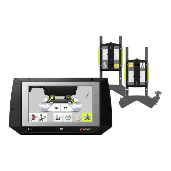
Page 21: Main Menu
MAIN MENU The EVO is provided with different programs for specific purposes. In the Main Menu you can select the program Press the ON button to start the system and that you want to use. the Main Menu appears. In the Main Menu you will also find the... - Page 22 APPLICATION PROGRAMS SYSTEM FUNCTIONS Shaft Alignment Horizontal Global Settings Machines Shaft Alignment Vertical Machines Wireless indicator Machine Defined Data Battery indicator MEMORY MANAGER Memory Manager...
-
Page 23: Shaft Alignment
SHAFT ALIGNMENT HORIZONTAL MACHINES INTRODUCTION Shaft alignment: Determine and adjust the relative position of two machines that are connected, such as a motor and a pump, so that the rotational centers of the shafts are collinear, when the machines are working in a normal operating condition. - Page 24 The EVO system has two measuring units machine can be made directly, according to that are placed on each shaft by using the the displayed values. fixtures supplied with the system. The alignment results can be saved in the memory manager. The measurements in the memory manager can easily be transferred to a PC for further documentation purposes.
- Page 25 PRE-ALIGNMENT FUNCTIONS e.g., there is enough space to move the machine). To obtain the best possible conditions for After the visual checks have been performed, shaft alignment, it is necessary to perform there are some conditions that must be some pre-alignment checks. In many cases it considered: is necessary to make these checks in order to obtain precise alignment.
- Page 26 MOUNTING Lift the open end of the chain, tension it so that the slack is removed and attach it to the The sensor marked “M” should be mounted hook. on the movable machine and the sensor marked “S” on the stationary machine. The sensors shall be assembled on their V-block fixture and placed on each side of the coupling.
- Page 27 Firmly tighten the chain with the tensioning Adjust the height of the sensor by sliding it on screw. Use the supplied tensioning tool. Do the posts until a line of sight is obtained for not over-tighten. If the shaft diameter is too both lasers.
- Page 28 The laser of the M-sensor can be adjusted with the adjustment screw on the top of the unit. There is normally no need to adjust the laser, but this might be necessary when measuring at long distances. NOTE: Make sure that the adjustment screw is secured with the locking nut after adjustment.
- Page 29 STARTING THE PROGRAM Start the program by touching the Horizontal Shaft Alignment icon in the Main Menu. Go to Settings for selecting measurement method and other settings.
- Page 30 SETTINGS Sampling time Opens window for selection of sampling time. Select normal or long sampling time. Long sampling time is suitable for high vibration environments. These settings are unique for this application. Tolerance table For most of the settings, the current selection is shown in the icon.
- Page 31 Adjustable screen filter Target values Opens window for Opens Target values. See chapter “Target values”. activating or deactivating the Turn off inclinometers adjustable screen filter. If the inclinometers are not functioning properly, e.g., in high vibrations, they can be Note: The adjustable disabled.
- Page 32 Add new machine with defined data Opens window for adding a new machine with defined data to Machine Defined Data. Entered data such as distances, Target values and tolerances, will be saved. Confirm Exits the Settings and returns to the application. 6.10...
- Page 33 ENTER DIMENSIONS The screen displays the movable machine. The traffic lights show green when the laser hits the detector. You must enter all the distances. The distance between the sensors, the distance between the center of the coupling and the M- sensor, the distance between the M-sensor and the first pair of feet and the distance between the first and the second pairs of feet.
- Page 34 SOFTCHECK Go to Softcheck for checking soft foot conditions. See chapter “Softcheck”. TARGET VALUES Go to Target Values for entering target values. See chapter “Target Values”. 6.12...
- Page 35 MEASUREMENT METHOD A green flashing arrow suggests suitable measurement positions. Tripoint™ method In the Tripoint method, the alignment condition can be calculated by taking three points while rotating the shaft at least 90°. NOTE: The shafts should be coupled during measurement in order to achieve as reliable and accurate results as possible, when using the Tripoint method.
- Page 36 MEASUREMENT POINT REGISTRATION Rotate the shafts to the next position. The shafts must be rotated over a minimum of 45°. Green sector shows permitted positions. Red Set the sensors at approximately the same sector shows forbidden positions. The rotational angle at the first measurement Register icon is not shown if the rotation is position.
- Page 37 Touch the register icon. Touch the register icon. This registers the second This registers the third reading. reading. TIP: When registering the third reading at the Rotate the shafts to the third position. 3 o’clock position, the sensors will already be in the right position for horizontal alignment.
- Page 38 MEASUREMENT RESULTS Within tolerance (green). Within double tolerance (yellow and inverted). Out of double tolerance (red and inverted). When a coupling is in tolerance in one direction, this is indicated with a check The Measurement Result screen shows symbol at the motor. coupling values and foot values in both the vertical and horizontal direction.
- Page 39 EVALUATING THE RESULT If the measurement result is within tolerance and has been saved, the system will The angle and offset values are used to recommend the user to exit the measurement. determine the alignment quality. These values are compared with the alignment tolerances to determine whether correction is necessary.
- Page 40 SHIMMING Go to alignment. The Shimming screen shows foot values in the vertical direction as suitable shim values (0.05 mm / 1 mil). The arrows show if shims must be added or removed to adjust the machine in the vertical direction.
- Page 41 ALIGNMENT Vertical direction If the machine has been adjusted vertically in the shimming screen, go directly to alignment in the horizontal direction. If the machine has not been adjusted in the shimming screen, alignment in the vertical direction must be done first. Rotate the shafts to the 12 or 6 o’clock position to adjust in the vertical direction.
- Page 42 Horizontal direction Check and re-measure Rotate the shafts back to the 12 or 6 o’clock position and check that the machine is still within tolerance. Alignment is now completed. To confirm the result, re-do the measurement. Re-measure. Rotate the shafts to the 3 or 9 o’clock position to adjust in the horizontal direction.
- Page 43 FEET LOCK FUNCTION Enter dimensions. The required distances are those between the first and second pairs of In some cases, the machine that is displayed feet on the stationary machine and between as the movable machine is not movable, or the first pair of feet on the stationary machine maybe some of the feet are not adjustable.
- Page 44 Feet Lock Shimming Feet Lock Alignment Shim values are shown for the two pairs of Live values are shown for the two pairs of feet feet that are not locked. that are not locked. 6.22...
- Page 45 SCREEN FLIP Screen Flip enables the user to see the machine set-up from the actual view. Select screen flip in settings. 6.23...
- Page 46 OTHER FEATURES Target Value symbol When Target Values are used Looseness indicator in the measurement, this is indicated with the Target Value symbol in the upper right corner The system has a function for detecting of the screen. coupling backlash and looseness in order to achieve optimum accuracy.
- Page 47 Measurement with disabled inclinometers During alignment, use the change view icon to change from horizontal to vertical view of the If the inclinometers are not functioning machine and vice versa. properly, e.g., in high vibrations, they can be disabled. • Turn off the inclinometers in Settings.
- Page 48 6.26...
-
Page 49: Shaft Alignment
Correction of vertical shaft alignment is done by moving the flange of the machine until the shafts are The EVO system has two measuring units aligned within given tolerances. A tolerance that are placed on each shaft by using the table is available in the system. - Page 50 and offset is corrected by moving them laterally. The alignment results can be saved in the memory manager. The measurements in the memory manager can easily be transferred to a PC for further documentation purposes. After rotating the shafts to different measuring positions, the system calculates the relative distance between the two shafts in two planes.
- Page 51 PRE-ALIGNMENT FUNCTIONS e.g., there is enough space to move the machine). To obtain the best possible conditions for After the visual checks have been performed, shaft alignment, it is necessary to perform there are some conditions that must be some pre-alignment checks. In many cases it considered: is necessary to make these checks in order to obtain precise alignment.
- Page 52 MOUNTING The sensors are mounted as described in chapter “Shaft Alignment Horizontal Machines”.
- Page 53 STARTING THE PROGRAM Start the program by touching the Vertical Shaft Alignment icon in the Main Menu. Go to Settings for selecting measurement method and other settings.
- Page 54 SETTINGS Sampling time Opens window for selection of sampling time. Select normal or long sampling time. Long sampling time is suitable for high vibration environments. These settings are unique for this application. Tolerance table For most of the settings, the current selection is shown in the icon.
- Page 55 Adjustable screen filter Opens window for activating or deactivating the adjustable screen filter. Note: The adjustable screen filter should be deactivated for normal operation, and only activated in environments with severe vibrations. Confirm Exits the Settings and returns to the application.
- Page 56 ENTER DIMENSIONS You must enter all the distances. The distance between the sensors, the distance between the center of the coupling and the M- sensor, and the pitch circle diameter and the number of bolts. Up to 8 bolts can be entered. MEASUREMENT METHOD The screen displays the movable machine.
- Page 57 MEASUREMENT POINT Tip: Mark the positions 1, 2 and 3 before you start measuring. REGISTRATION Set the sensors at approximately the same rotational angle at the first measurement position, with bolt number 1 to the right. Touch the register icon. Place yourself at the position corresponding to the second measurement position, where it This registers the first reading.
- Page 58 Rotate the shafts 90° to the second position Rotate the shafts 90° to the third position, to (where you are standing). the left. Touch the register icon. Touch the register icon. This registers the second This registers the third reading. reading.
- Page 59 MEASUREMENT RESULTS Within tolerance (green). Within double tolerance (yellow and inverted). Out of double tolerance (red and inverted). When a coupling is in tolerance in one direction, this is indicated with a check symbol The Measurement Result screen shows at the motor. coupling values in both directions, and bolt values.
- Page 60 EVALUATING THE RESULT The angle and offset values are used to determine the alignment quality. These values are compared with alignment tolerances to determine if any correction is necessary. If suitable tolerances are selected in the tolerance table, the symbols described above indicate if the angle and offset values are within tolerance or not.
- Page 61 SHIMMING When shimming is completed, continue to alignment for adjustments of parallel offset. Go to alignment. The Shimming screen shows bolt values as suitable shim values (0.05 mm / 1 mil). Adjust the angular error by placing shims under the bolts as required. The arrow shows if shims must be added to adjust the machine.
- Page 62 ALIGNMENT tolerances once the adjustments are completed. Alignment is now complete. To confirm the result, re-do the measurement. Re-measure. If the angular error has been correctly adjusted in the shimming screen the angular value should now be in tolerance. Now adjust the parallel offset in both directions.
-
Page 63: Machine Defined Data
MACHINE DEFINED DATA INTRODUCTION If the sensors are placed at the same place each time a machine (or more identical machines) is measured, it can be convenient to preload the relevant parameters. The data that can be preloaded are: • The name of the specific machine. - Page 64 STARTING THE PROGRAM Select machine Machines can be selected by touching its Start the program by touching machine name. the Machine Defined Data icon in the Main Menu. This starts Shaft Alignment with machine defined data for the selected machine. USING MACHINE DEFINED DATA A list of machine types with preloaded data is shown.
-
Page 65: Softcheck
SOFTCHECK™ STARTING THE PROGRAM Start the Softcheck by touching INTRODUCTION its icon in the Shaft Alignment program. A soft foot condition needs to be corrected before any alignment takes place. If not, the measurement result will be of no value. It is Place the sensors at the 12 o’clock position. - Page 66 MEASUREMENT VALUE REGISTRATION Register the measurement value by touching the confirmation icon. Select a bolt of your choice by touching its icon. Loosen the bolt fully and wait a few seconds. Tighten the bolt firmly, preferably with a dynamometric wrench. Register the measurement value.
- Page 67 MEASUREMENT RESULT AND CORRECTIONS Continue with the rest of the bolts. Make the necessary corrections and then Re-measurements can be done at any time check each foot again (the values show by touching the icon for the requested bolt approximately how many shims that are again.
-
Page 69: Target Values
In the EVO system, you can pre-set target values before starting your alignment work. Accepted values are feet values and angle and offset values. - Page 70 STARTING THE PROGRAM FEET VALUES Start the Target Values program by touching its icon in Settings. Touch the feet value boxes. Enter target values for the feet in mm or mils according to the pre-set measurement unit together with the required distances. Select one of two ways to express the offset values: Feet values or angle and offset values.
- Page 71 In the example above, the stationary machine will shrink vertically by 0.12 mm at the rear feet and 0.09 mm at front feet while the movable machine will expand 0.04 mm while running. Horizontally, the rear feet will move 0.05 mm After having entered these feet values, the towards you and the front feet will move 0.03 system calculates how the movable machine...
- Page 72 ANGLE AND OFFSET VALUES In the example above, the movable machine should be vertically adjusted to a position with Touch the value boxes and enter target an angular misalignment of +0.05 mm/100 values for the angles in mm/100 mm and mm and an offset of target values for the offsets in mm, or -0.06 mm.
- Page 73 10.5...
- Page 74 10.6...
-
Page 75: Tolerance Table
Machine alignment should be carried out within the manufacturer’s tolerances. The table provided in EVO can be helpful if no tolerances are specified. The suggested tolerances can be used as a starting point for developing in- house tolerances when the machinery manufacturer’s recommended tolerances are... - Page 76 CUSTOMIZED TOLERANCES A customized tolerance can be entered at the last row of the tolerance table. Enter customized tolerance by touching any of the fields, name/rotation speed to the left and tolerance values to the right. Tolerance Table inch-mode SELECT TOLERANCE Select the tolerance to use in the alignment by touching its check box to the left.
-
Page 77: Memory Manager
MEMORY MANAGER Select files Touch the check box to the left FILE MANAGER to select a file. Delete Deletes selected file. Archive Goes to archive (only available when it contains Open file folders with older files). Touch a file to open it. Exit Scroll Exits the Memory Manager. - Page 78 The Memory has the capacity to store approximately 1200 measurements. When the number of measurements, exceeds 100 measurements in the file manager, a folder with the older files will be automatically created. These folders can then be found in the archive. NOTE: When there are a lot of files in the memory, processing can be slow.
- Page 79 SAVE MEASUREMENT Enter file name Touch the white field to enter a file name. Confirm Confirm. When saving a measurement, both a text file and a picture file (bmp) are created. 12.3...
- Page 80 TRANSFER FILES TO A PC In the PC there will be two files for each measurement; a picture file (.bmp) and a text Turn on the display unit and stay in the file (.txt). The picture file shows the same Main Menu.
- Page 81 SHAFT ALIGNMENT HORIZONTAL MACHINES The screen displays measurement results, dimensions, target values if any, file name, date and time, serial number of the display unit, program, program version and tolerances. Exit the measurement file. 12.5...
- Page 82 SHAFT ALIGNMENT VERTICAL MACHINES The screen displays measurement results, dimensions, file name, date and time, serial number of the display unit, program, program version and tolerances. Exit the measurement file. 12.6...
-
Page 83: Global Settings
GLOBAL SETTINGS Date and time Opens window for date and time settings. Measurement unit Changes between mm mode and inch mode. Bluetooth settings The global settings menu includes settings that are universal for all applications. Opens window for bluetooth settings. For most of the settings, the current selection is shown in the icon. - Page 84 Pair able units will appear in the search list to the left. The wireless units must be switched on for Communication the display unit to discover them. The display unit will only discover units approved by Activate Bluetooth. ACOEM. Deactivate Bluetooth. 13.2...
- Page 85 Touch the units to pair in the search list. Units that are paired to the display unit are (Maximum two units.) shown in the boxes beside the blue B. Paired units will be moved to the boxes The display unit will only communicate with beside the blue B.
- Page 86 Unpairing Bluetooth units Touch the delete icon to unpair units. 13.4...
-
Page 87: Display Unit Evo D
DISPLAY UNIT EVO D 5” Touch screen On button with status LED Continuously green – ON Display Unit battery status Continuously green – connected to charger and battery fully charged Continuously amber – connected to charger and charging Flashing red - <10% battery... - Page 88 OPERATING MODES CONNECTIONS The display unit has two operating modes: On The main connection for the Display Unit is and Off. the built in Bluetooth connection. See chapter “Global settings” for instructions on how to To turn on the unit, press the pair measurement units.
- Page 89 POWER SUPPLY status LED. The charging time is approximately 8 hours for fully drained The EVO D is powered by a high-capacity batteries. The charging time will be longer if rechargeable Li-Ion battery in the display unit, the unit is turned on while being charged.
- Page 90 BACKLIGHT RESUME FUNCTION If no icon is pressed within 30 minutes the If the system is turned off due to low power, backlight will dim automatically. the resume function will save the data. Press anywhere on the screen to turn the backlight on again.
- Page 91 UPGRADING THE SOFTWARE NOTE: A zipped file must be unzipped before copying it to the display unit. Any upgrades of the software will be distributed or made available for download on Disconnect the display unit from the PC our website. and wait until the display unit turns itself Turn on the display unit and stay in the off (this can take several minutes).
- Page 92 CALIBRATING THE TOUCH SCREEN NOTE! In order to make the touch screen to respond For best results please use a to the icons on the display, it may be stylus for calibration. necessary to recalibrate it from time to time. Screen calibration procedure: •...
-
Page 93: Sensors M3 And S3
SENSORS M3 AND S3 ON/OFF button with status indication Continuously green – On Switching green/red – Gyro activated. Mini USB for charging Laser transmission indication LED Green – laser transmission Bluetooth indication LED Continuously blue – paired and ready. Flashing blue – searching/ready to pair No light –... - Page 94 Battery status LED One LED continuously red – less 10% charge left. One LED flashing red – less than 5% charge left. One LED continuously orange – charging One LED continuously green – fully charged. Battery status LED when battery button is pressed Battery status button –...
- Page 95 OPERATING MODES CONNECTIONS M3 and S3 units has two operating modes: Bluetooth connection On and Off. The main connection for M3 and S3 units is Turn the units on and off by pressing the the built in Bluetooth connection. The units ON/OFF button firmly.
- Page 96 Li-Ion (continuously on). batteries supplied by ACOEM. Improper replacement of batteries can cause damage The M3 and S3 units can be charged with the and risk for personal injury. Please refer to the supplied combined charger.
-
Page 97: Technical Specification Evo D
TECHNICAL SPECIFICATION – EVO D Art. No. 1-0934 Housing Material Brushed Anodized Aluminum frame and high impact ABS plastic over molded with TPE rubber Operating Temp -10 to 50°C (14 to 122°F) Battery Charging Temp, system on 0 to 40°C (32 to 104°F) Storage Temp -20 to 70°C (-4 to 158°F) - Page 98 5” High Impact Polyester laminated touch Interface screen with enhanced transmission and reduced glare Connectors 1 USB 2.0 mini port (IP 67) Wireless communication Class II Bluetooth transmitter with multi-drop capability Power supply High performance rechargeable Li-Ion battery or external power supply Operating time 8 hours continuous use Battery Charging time (system off, room...
-
Page 99: Technical Specification M3 And
TECHNICAL SPECIFICATION – M3 AND S3 Art. No. M3 1-0913, S3 1-0914 Housing Material Anodized Aluminum frame and high impact ABS plastic over molded with TPE rubber Operating Temp -10 to 50°C (14 to 122°F) Storage Temp -20 to 70°C ( -4 to 158°F) Long term storage temp Room temp. - Page 100 Detector resolution 1 µm Measurement accuracy 0,3% ± 7 µm Signal processing: Digital signal processing with Sidespot rejection, edge detection, ambient light elimination and anti-vibration mode Ambient light protection Optical filtering and digital ambient light signal elimination Inclinometer: Dual High Performance MEMS inclinometers Inclinometer resolution 0,01°...
- Page 101 Battery Capacity 10.4 Wh LED indicators Unit state, laser transmission and 5 battery status indicators with instant battery check Specifications are subject to change without notice. *Gyroscope functions are not implemented in the EVO software. 17.3...
- Page 102 17.4...
- Page 104 Publication No. P-0251-GB © 2021 ACOEM AB, Mölndal, Sweden All rights reserved. No part of this manual may be cop- ied or reproduced in any form or by any means without prior permission from ACOEM AB acoem.com...
Need help?
Do you have a question about the EVO and is the answer not in the manual?
Questions and answers