
Related Manuals for ACOEM ORION


Summary of Contents for ACOEM ORION
- Page 1 User Manual ORION Smart Vibration Monitoring Terminal ORION Smart Vibration Monitoring Terminal User Manual...
- Page 3 : application FW 2.00 and higher, metrology FW 2.36 and higher 01db.support@acoemgroup.com Copyright © 2024, Acoem France This document is the property of Acoem France SAS. Any dissemination, copying or publicising of this document, in whole or in part, is prohibited without the owner’s written authorisation...
- Page 4 Table of contents CHAPTER 1 GENERAL PRESENTATION .................... 9 Introduction ..........................9 Measurement domains......................9 Overview ..........................10 Access HATCH (details) ....................... 11 Breathing valve (details) ..................... 13 GPS (Optional) ........................13 1.6.1 Inputs and Outputs (Details) ..................14 Inputs sensors Description ....................14 1.7.1 Triaxle internal Accelerometer ..................
- Page 5 5.2.3 Summary of all data stored in ORION ................34 Data types signals ........................ 37 Method applied to determine Dominant Frequency DF: ........... 37 Method applied to determine the type of signal (continuous or transient) ....40 CHAPTER 6 WEB INTERFACE ......................41 Description of the web interface ..................
- Page 6 SMS functionalities ......................118 7.7.1 SMS events content ..................... 118 7.7.2 SMS system alarms ..................... 121 7.7.3 Automatic SMS actions: ....................121 7.7.4 Actions on SMS sent to the instrument: ..............121 HTTP command lines (no need for H option) ..............121 HTTP commands .........................
- Page 7 If this is not the case, please notify ACOEM or its approved representative without further delay. You are advised to keep the packaging in case you need to return your equipment for maintenance at ACOEM’s premises.
- Page 8 Download all 01dB technical documents (manual, release note…) and 01dB software, follow your tickets (technical requests) http://support.01dB.acoemgroup.com Further information For further information Visit our website : www.acoem.com Follow us on Linked-In: https://www.linkedin.com/company/acoemgroup Contact our customer service Department by e-mail at 01db.support@acoem.com ...
- Page 9 CHAPTER 1 ENERAL PRESENTATION NTRODUCTION ORION is a new generation upgradeable vibration measuring instrument, integrating innovative technology. The programming of all available functions (Input / Output / Storage…) allows meeting best the user’s requirements. The data measured with the instrument are displayed on a remote screen, such as a...
- Page 10 Vibrations on sensitive equipment: e.g. work in the museum neighbourhood or sensitive computers. The evaluation of vibration is based on velocity or acceleration acquisition on three axes X, Y, Z in the frequency bands 0.4Hz-150 Hz or 315 Hz. According to the standards of different countries, the measured quantities are compared to values or tolerance curves whose values may differ depending on the frequency.
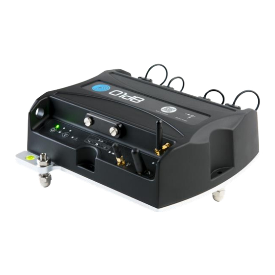
- Page 11 Back view 09 – C1 - External sensors 10 – C2 - TTL Output 11 – Breathing valve 12 – C3 - External Power 13 – C4 – LAN/External Power over Ethernet (PoE) Bottom view 14 – Adjustable screws 15 – Not adjustable screw HATCH ( CCESS DETAILS...
- Page 12 It gives access to several slots: 16 – SD card slot 17 – Micro USB connector for USB host connexion (allows for reading the SD card content). 18 – Sim card slot. 19 – Micro USB connector for service (only manufacturer use)
- Page 13 GPS patch (ACE1094) to be able to mount the patch at a different location from where ORION is for better satellites reception; 3 meters cable. Antenna (ACE1105) mounted directly on ORION if satellites reception is satisfactory at ORION location.
- Page 14 1.6.1 Inputs and Outputs (Details) All external circuits connected to ORION should be non-hazardous voltage and energy sources be limited within the meaning of the IEC61010-1 standard. Do not exceed the maximum input voltage on the connectors. Maximum voltage Connector #...
- Page 15 1.7.3 Microphone external sensor (optional) it is also possible to connect on External sensors connector (C1) a microphone to measure the noise associated with the vibration (blast). Please consult us about this feature.
- Page 16 1.7.4 Markings on the keyboard Symbol description Power button Power LED Lock LED Sensor error LED Wi-Fi button Wi-Fi LED Memory SD (solid disk) card slot (Behind the hatch) Micro-USB Factory service only (Behind the hatch) SIM card slot (Behind the hatch) Micro-USB Connector (Behind the hatch) Ethernet LED...
- Page 17 GSM antenna connector LED for quality signal...
- Page 18 CHAPTER 2 NSTALLATION The equipment can be deployed in different configurations. All configurations are not allowed according to the environment. It is essential to observe the deployment and safety rules that apply to each use case. SE CASES PREREQUISITE Use cases are exhaustively described; therefore, the instrument should never be with a use case neither described nor allowed in this user manual.
- Page 19 IEC61010-1 standard. If the TTL output of the instrument ORION is connected to a device, this device should be non-hazardous voltage and energy source be limited within the meaning of the...
- Page 20 The radio device (WIFI, GSM-3G, GPS) may be used anywhere. (Respecting national regulations, RED, FCC, IC). ARTH CONNECTION The protective Earth connexion is possible on the screw terminal using the cable as shown on the picture. The recommended tightening torque is 3N.m Screw Terminal The other side of the earth cable must be connected to a good quality protective earth.
- Page 21 An existing protective ground may either be used in replacement of the ground rod. Anyhow, it must compliant to the IEC61010-1 standard.
- Page 22 The battery pack must be replaced at factory only by authorized personnel EPLACEMENT PARTS The parts of the device ORION that could be replaced by the owner are: The three feet, spherical or sharp end The antennas ...
- Page 23 CHAPTER 4 EYBOARD USE See chapter 1.7.4 Markings on the keyboard about the description of the keyboard 4.1.1 Power button If instrument is off and you want to turn on Press the power button to turn on The unit state is now in Ready Mode if not programmed to auto start log. ...
- Page 24 Wi-Fi Led is flashing 2 seconds and turn on (Blue) Wi-Fi setup is now factory parameters When a SSID connection is established with ORION Wi-Fi Led change from on to flashes continuously When a SSID connection is established with ORION Wi-Fi Led change from flashes continuously to on ...
- Page 25 Lock LED is on. To unlock your instrument Simultaneous short press the 2 buttons POWER & Wi-Fi Lock LED is off. 4.1.4 Reset factory To hard reset and return to factory settings Simultaneous long press (5 seconds) ...
- Page 26 4.2.3 LED Lock (yellow): If keyboard locked yellow LED on If keyboard unlocked yellow LED off 4.2.4 LED Ethernet (yellow): Operation corresponding to a standard Ethernet connection (on when connected and flashes while data exchange).
- Page 27 LED flashes on Production mode LED fast flashes during update process. 4.2.6 LED Battery (2 colours red/green): If ORION turned on and connected on charger (including POE) Green LED on If ORION turned on and powered by battery only ...
- Page 28 BOUT OPTIONS This manual describes all the functions of the instrument, for all options. Some functions presented here are available only if the instrument has the corresponding licence. Refer to § 10.2 Table of options for more information.
- Page 29 TARTING THE INSTRUMENT AND ITS REMOTE WEB INTERFACE 4.4.1 QR code on top of the instrument ORION is delivered with a unique QR code providing the following information: Model type: ORION Manufacturer internal code: VMT1002000 Serial #: 10025 ...
- Page 30 CHAPTER 5...
- Page 31 CHAPTER 5 EASURED AND STORED DATA POSSIBLE SIMULTANEOUS ACTIVATION OF UP TO STANDARDS Application 1: Construction : DIN 4150-3, Circ, BS 5228-4 or BS 5228-2 Application 2: Construction : Arrêté Application 3: Occupants: DIN 4150-2 Application 4: Occupants: ISO 2631_1989 Application 5: Occupants: ISO2631_2003 Application 6: Occupants: BS 6472-1 Application 7: Sensitive equipment (under development)
- Page 32 DFj: Dominant Frequency: frequency corresponding to the maximum of an FFT spectrum centred at the particle velocity time of the max # ▲: number of exceedances...
- Page 33 5.2.2 Occupants 5.2.2.1 DIN 4150-2 VDVtk: Vibration dose value: cumulative measurement of the vibration level received from start of the measured period. Lptk: « ground borne noise »: estimated structure borne noise based on the measurement of the RMS vibration velocity measured on a radiating surface (A weighted).
- Page 34 A*Tjk: RMS recomposed acceleration 1/3 oct F1 and 1/3 oct F2 5.2.2.4 BS 6472-1 2008 Specific data type: Lpk: « ground borne noise »: calculation based on Lvk (RMS vibration velocity level) 5.2.3 Summary of all data stored in ORION Data type Period Storage Display...
- Page 35 Data type Period Storage Display Time history Table AwTik Value Time history Table AwpeakTik Value Time history Value Frequency Table Type (transient or continuous) Time history Threshold exceeded (yes/no) Threshold PPVjk/DFjk Kurtosis template (data not stored if « Arrêté » only is selected) Value Table...
- Page 36 Data type Period Storage Display Spectrum Value Table AnTj Spectrum Value Table A*Tj Spectrum # ▲ Globa # exceedance table ▲ Only if « DIN » or « Circulaire » selected PPVjk/Fdjk # ▲ Globa # exceedance table ▲ Only if « BS » selected PCPVj/Fdj # ▲...
- Page 37 ATA TYPES SIGNALS Signal recorded by the instrument are of 2 different types: Raw signals coming from the sensor after conditioning Samples used for dominant frequency calculation (refer to § 6.3 Method applied to determine Dominant Frequency DF:). If the sensor used is an accelerometer (which is the case for internal sensor and for external accelerometer), raw signal is acceleration.
- Page 39 3. determination of DF Dominant Frequency DF Dominant Frequency...
- Page 40 ETHOD APPLIED TO DETERMINE THE TYPE OF SIGNAL CONTINUOUS OR TRANSIENT The instrument calculates the Kurtosis value K of the vibration signal and determines whether the signal is continuous or transient. The Kurtosis K is defined as the 4th-order centred moment of the random variable: it characterizes the flattening of the probability density curve.
- Page 41 CHAPTER 6 EB INTERFACE ESCRIPTION OF THE WEB INTERFACE The web interface (Instrument’s embedded application) has been designed for access through the Internet. The instrument embeds a Web server. The application firmware is then embedded in the instrument as HTML pages. Remote access to the instrument can be achieved using an Internet navigator on all types of remote control (PC / Pocket PC / Tablet PC / Internet Tablet / Netbook or Smartphone).
- Page 42 Zone 1 Zone 2 Zone 3 The status bar contains different icons and informs the user on the status of the instrument. The working zone allows displaying the main and secondary menus (as HTML page tabs), measured levels and associated graphs. Context commands of the keys are shown as text and icons.
- Page 43 6.1.1 Web interface screens 6.1.1.1 Start-up screen When opening the Web interface, the following screen is displayed: Start-up screen The operator must enter the production output IP address of the instrument (http://192.168.0.1 if Ethernet connection, http://192.168.1.1 if Wi-Fi connection) in the Web browser in order to access the web interface, after configuration of the network (refer to §...
- Page 44 6.1.1.3 Main menu The main menu of the web interface is made up of several tabs. The selected tab is displayed in a light colour (grey background): Infos. tab: it contains man information. This menu is displayed by default when the ...
- Page 45 6.1.2 The status bar Various icons are displayed, depending on the status of the instrument: Current mode: Ready, Logging and Stabilisation. Battery level (charged or discharged): charge symbol icon and % charge when charging, battery symbol icon and % charge remaining off charging time. When the charge is <...
- Page 46 6.1.3 Command zone The measurement command bar contains 3 command buttons. It is accessible from all screens. Buttons are blue if they can be activated, otherwise they are grey. The Switch off command can be used to turn off the instrument. Beware: once switched off remotely, the only way to turn it on again is to press the button ON/OFF on the instrument.
- Page 47 Note: the active measurement configuration is tagged with a star (here, default*). 6.4.1.1 Edit a configuration In Edit mode, the pull-down menu becomes an input field where the name of a new configuration can be entered. Once new parameters have been properly entered, press Save to save the edited configuration.
- Page 48 Each of the tabs gives access to the activation of a transducer for a selected standard (internal or external): Except for “arreté du 22 septembre 1994” that can be selected together with “circulaire du 23 juillet 1986”, once a sensor is activated for one standard, it cannot be activated for another one.
- Page 49 6.4.2.1.2 Construction 6.4.2.1.2.1 DIN 4150-3 The user can select the configuration to use between lines 1 to 3 for Foundation, Highest floor or Pipe network in short or long-term conditions. Criteria for trigger are based on PPVjk/DFjk. Refer to DIN 4150-3 standard for more information). Tolerance tables for PPVjk/DFjk are updated accordingly: Foundation/short term...
- Page 50 Highest floor/long term Pipe network/short term Pipe network/long term...
- Page 51 6.4.2.1.2.2 Circulaire du 23 juillet 1986 The user can select the configuration to use between Resistant constructions, Sensitive constructions and Very sensitive constructions. The type of signal (continuous or transient) can be automatically detected or manually selected. Criteria for trigger are based on PPVjk/DFjk. For more information, refer to circulaire du 23 juillet 1986: https://www.legifrance.gouv.fr/affichTexte.do?cidTexte=JORFTEXT000000866509 Tolerance tables for PPVjk/DFjk for the various cases...
- Page 52 6.4.2.1.2.3 Arreté du 22 septembre 1994 Opposite to the other 4 standards implemented, the criteria for trigger is related only to a tolerance limit on a specific weighted Peak Particle Velocity signal designated Vpmaxjk. Frequency weighting Vpmax [HZ] The regulation can be downloaded directly from the web interface by pressing...
- Page 54 6.4.2.1.2.4 BS 5228-4 The user can select the configuration to use between 4 different cases. Criteria for trigger are based on PCPVj/DFj. The type of signal (continuous or transient) can be automatically detected or manually selected. Refer to BS 5228-4 standard for more information. Tolerance tables for PCPVj/DFj for continuous and transient signals 6.4.2.1.2.5 BS 7385-2 The user can select the configuration to use between 4 different lines.
- Page 55 …) the user must select the type of KBFTr calculation: either considering rest periods or not. The selected data will be stored for further post-processing. ORION can compare real time KBFT measured to the limit determined in the table and alarm on exceedance.
- Page 57 6.4.2.1.3.3 ISO 2631-2 1989 Default Location: Residential Default type signal: Automatic Base curves selection by default: known axes If User defined base curves are selected, then the bandwidth for all measured values is defined up to 315 Hz The user has the choice to calculate or not the recomposed values A*Tjk and the ...
- Page 58 New campaign starts at night time and day time Night time start ≤ 23 h Day time start <night time The Multiplication factor table is editable; default values the specified min value. possible values between 1 and 128 reference base curves hyperlink allows the following curves to be displayed: ...
- Page 59 0,0721 0,025 0,0902 0,0313 0,114 0,0394 0,144 0,05 0,1803 0,0626 0,2252 0,0782 0,2882 0,1001 0,3601 0,1250 0,4501 0,1563 0,5670 0,1969 Button allows for storing the modifications By pressing DEFAULT, the values are restored to the original ones. 6.4.2.1.3.4 BS 6472-1 The user can select different time intervals to start VDV dose calculation.
- Page 60 Moreover, the user can select different time intervals for ground borne noise threshold levels, set by default to 45 dBA 6.4.2.2 Param. sub-menu The Param. sub-menu allows to adjust acquisition parameters: Tj, logging period, corresponds to the analysis period determining peak particle velocity and associated dominant frequency Ti, fast logging period, corresponds to additional information on Peak Particle velocity for a high-resolution time history.
- Page 61 For Kurtosis parameter, please refer to § 6.4 Method applied to determine the type of signal (continuous or transient).
- Page 62 Send HTTP trigger #: sends an http command to another device on the same network (DUO, FUSION , CUBE, ORION) allowing the creation of a trigger by HTTP command; # [from 1 to 5 or None], by default None To device IP:PORT: IP:PORT of the device that receives the HTTP trigger ...
- Page 63 SMS text: text sent by the instrument once a warning has occurred Alarm #: for internal use (01dBWebMonitoring) Number of occurrences: for internal use (01dBWebMonitoring) Days of the week: select the day(s) of the week when the event will apply (default ...
- Page 64 6.4.2.3.3 Standard based events parameters Standard based events cannot be modified unless the standard referring to has been modified by the user using the sub-menus of the Store tab (refer to § 7.3.2.1.1 Principles) Event name is a hyperlink opening a new window with the tables describing the various selected standard user cases (refer to §...
- Page 65 Variable condition in Store tab InternalAwjk x and y, or z Trigger on the level indicated in Store tab InternalAwpeakjk x and y, or z Trigger on the level indicated in Store tab InternalMTVVjk x and y, or z Trigger on the level indicated in Store tab ExternalVpmaxjk x and y, or z...
- Page 66 Logic for triggers: controls whether the combination of triggers is with the logic "and" or "or" trigger #: selection of the trigger. Possible selection between i_1 and i_5. press « + » creates trigger i_2; press « -. » deletes trigger i_2. The following actions are applied to the selected trigger: Trigger type: variable selectable value among the values described below ...
- Page 67 Variable condition InternalPPVjk x and y, or z Exceeded trigger level InternalPCPVj Exceeded trigger level InternalPVSj Exceeded trigger level InternalKBFTmjk x and y, or z Exceeded trigger level Internal KBFTrjk x and y, or z Exceeded trigger level InternalAvj Exceeded trigger level InternalA*jk x and y, or z Exceeded trigger level...
- Page 68 6.4.2.4 Timer sub-menu Timer sub menu allows to program timers. The Timer mode can be exit by changing the configuration or by selecting a configuration where the timer is not active Types of timer Immediate: corresponds to the manual mode with no timer (immediate start of the ...
- Page 69 # of cycles: number of programmed starts. “No limit” corresponds to a mode where the instrument keeps running until the battery is empty or until the memory is full. Value ranging from 1 to 9999. Periodicity: corresponds to the time period between each timer. This function is ...
- Page 70 6.4.2.6 Misc. sub menu # active periods: the number of active periods is selectable between 2 and 4; inactive periods are greyed. Delete oldest measurement sessions: allows for automatic deletion of oldest measurement sessions If disk space below: value compared to disk space every time a measurement ...
- Page 71 NFOS MENU 6.5.1 Measurement configuration The name of the active configuration is a hypertext link that allows opening a new tab describing the entire active measurement configuration: Stored indicators Storage parameters Type of coding Time parameters Signals recording parameters…...
- Page 72 6.5.2 Location Location: in this field the user inputs the name of the test site. This name then defines the name of the directory used to store the measurement sessions. This text field is accessible only if the instrument is in Ready mode and contains a maximum of 12 characters.
- Page 73 GSM IP: public IP address on cellular network Ethernet IP: IP address for Ethernet link connection. Wireless IP: IP address for wireless infrastructure connection Serial #: serial number of the instrument Free memory: memory capacity remaining on SD card. ...
- Page 74 6.5.3.1 System log Pressing the System log icon opens a new tab listing all events, with 3 levels: CRITICAL: critical events are listed in red. WARNING: events requiring attention are displayed in orange. INFORMATION: informative events are listed in green. ...
- Page 75 Interactive zone of the table in Log mode 6.6.2 Real time displays in Ready mode 6.6.2.1 Construction standards The time history display shows data at a 1 sec. resolution with an X axis of 2 minutes.
- Page 76 If the “Arrêté” is the only selected standard, then Vpmax is checked systematically activated and unchangeable. If “Arrêté” is not selected, then the Vpmax box is greyed out:...
- Page 77 6.6.2.2 Occupants standards In DIN 4150-2 standard, KBFT is updated every second; In ISO 2631 2003 standard the different data types are displayed and updated every second. VDV is reset every time a display is initialised.
- Page 78 In ISO 2631 1989 standard it is possible to select either time history of Aw or Awpeak, or spectrum, updated every second. In case of spectrum selected, the interface displays the continuous and transient tolerance curves. By using the arrows, the cursor moves accordingly.
- Page 79 In BS 6472-1 standard, VDV and Lp are updated every second; VDV is reset every time a display is initialised.
- Page 80 6.6.3 Real time displays in Log mode 6.6.3.1 Prerequisite For all display types, the following is applicable: Manual coding is done pressing one of the 5 code buttons: Once code is activated, the button becomes green: . By pressing again, the code is deactivated, and the button becomes blue again Manual signals recording is activated pressing the button: and becomes green...
- Page 81 6.6.3.2 Possible displays function of the selected Construction standard The following table synthesizes the different possibilities for displaying data and tolerance curves: DIN4150-3 Circulaire Arrêté BS-5228 BS-7385 Stored Time History PPV/FD TCCT Stored Time Vpmax History PPV/FD Stored Time PCPV History PPV/FD TCCT...
- Page 82 6.6.3.4 Particular case: Arrêté du 22 septembre 1994 (French Regulation) If “Arrêté” is the only selected standard, then the Vpmax box is systematically checked and unchangeable. If the order is not selected, then the Vpmax box is empty and greyed out. If Vpmax is selected, the values displayed become those calculated for PPV.
- Page 83 6.6.3.5.2 DIN 4150-3 standard The tolerance curve is displayed in red. The couples of data measured are red squares (except for the ongoing acquisition: green square 6.6.3.5.3 Circulaire du 23 juillet 1986 (French Regulation) The following description applies for “Circulaire” (criteria on PPV). Tolerances curves are of 2 types: Transient signal type exceedance in red with following...
- Page 84 6.6.3.5.4 BS 5228-4 and BS 7385-2 standards The following description applies for both BS standards (criteria on PCPV). Tolerances curves are of 2 types: Transient signal type exceedance in red with following pictogram: Continuous signal type exceedance in blue with following pictogram: Same colours apply for couples of values displayed:...
- Page 85 6.6.3.6 DIN 4150-2 KBFTm KBFTr When KBF is selected, the tolerance curve in red is displayed together with the time history...
- Page 86 6.6.3.7 ISO 2631-2 2003 In this mode the trigger level appears on the displayed data type, if programmed in the Store tab. 6.6.3.8 ISO 2631-2 1989 6.6.3.8.1 Time history mode...
- Page 87 The active data types are displayed. If a data type is not activated (as for instance A*or Av), then the table remains with “---" 6.6.3.8.2 Spectrum mode In case of automatic detection of signal type, the colour of the spectrum depends on the type of signal (blue for continuous, red for transient, similar to the colours of the base curves).
- Page 88 VDV and Lp can be displayed for each axis 6.6.3.9.2 Graph scaling For better readability, scaling is fixed and related to the tolerance curves applied: the ordinate max value is calculated as follows: For VDV: smallest value among (50 ; 25 ; 10 ; 5 ; 2.5 ; 1 ; 0.5 m/s1.75) above: ...
- Page 89 TORED DATA MENU 6.7.1 Main page The main page of the Stored data tab is shown below: List Commands The Stored data tab includes 2 zones: List zone lists all measurement sessions. For each session, the following information is displayed: name of site, starting date and time, duration, possibility to select for the user.
- Page 90 6.7.2 Selection of a measurement session for the display of data values To view a measurement session, the operator must select the corresponding line in the list of measurements by clicking on one of the lines to open the interface showing the stored data: Hyperlink Default view is PVSj time history except if “Arrêté”...
- Page 91 As for real time display, if the standard is compatible (all except “Arrêté”) the user can select the different data view with couples of data PPVjk/DFjk and PCPVj/DFj using the selection inside the table: Note: Quality status displayed by axis, by sensor. Short circuit / open circuit (?), Overload (˄), under load (only displayed if active during any the measurement time) (˅) YSTEM MENU...
- Page 92 Date & time: allows for manual input of date and time parameters. Time zone: allows selecting the relevant time zone. Automatic daylight savings: allows for automatic considering of Summer time/Winter time. Auto. GPS time synchronisation: allows for automatic synchronisation of the clock ...
- Page 93 DHCP field is selected, a private IP address and related subnet mask are automatically assigned. IP address: Ethernet IP address Subnet mask Default gateway 6.8.2.2 Wi-Fi sub-menu ORION has the possibility to be setup either as a WAP (Wireless Access Point) or as a station (Infrastructure).
- Page 94 6.8.2.2.1 Access point mode In this mode, ORION acts as a wireless router. Therefore, to connect to ORION, 1. select in the list of wireless networks the SSID corresponding to ORION (default is ORION_[S/N] 2. type in your web browser the IP address of the instrument (default 192.168.1.1).
- Page 95 6.8.2.2.2 Station mode In this mode ORION can connect to a WAP (Wireless Access Point). The following parameters can be configured by the user: SSID name: Name of the Wi-Fi Access point to which the instrument connects to. Authentication: choice between WEP, WPA_PSK, WPA2_PSK or inactive.
- Page 96 6.8.2.3 GSM sub-menu The following parameters can be configured by the user: SIM PIN code. Access point name (APN). SIM user name: required by some operators in some countries. SIM password: required by some operators in some countries. ...
- Page 97 Acoem representative. Please note that connecting to Cadence monopolises the FTP 1 server, even if you have entered information. Please use FTP 2 if you want the ORION to send information to Cadence and to another server in parallel.
- Page 98 Client sub menu sets up the parameters and data stored in the SD card sent by ORION to an FTP server. Up to 2 different servers can receive data from the instrument by selecting server 1 and/or server 2. There is no distinction on the selected sensor(s): if internal and/or external sensor(s) is(are) selected, data from all active sensors will be sent.
- Page 99 Velocity signals for DF calc.: signals used for DF calculation (refer to § 6.2 Data types signals). 6.8.2.5.5 Push every minute This functionality allows ORION to send every minute the most important information for State Of Health (SOH) State of Health data (in .XML format) contains the following information: <StateOfHealth version="1">...
- Page 100 « Model » Tag: commercial name of the device « SerialNumber » Tag: Serial number (typically 5 numbers) « Device » Tag: 01dB/CMG device type (ORION=1800) « TimeZone » Tag: Official name of the time zone (ex: « Romance Standard Time » for Paris) «...
- Page 101 <FreeMemoryKb>520000</FreeMemoryKb> <NbSatellites>6</NbSatellites> <Latitude>45.76</Latitude> <Longitude>4.84</Longitude> <GSMStrength>3</GSMStrength> <GSMNetwork>3</GSMNetwork> <GSMIP>90.52.36.21</GSMIP> <InternalSensorState>1;1;1</InternalSensorState> <ExternalSensorState>0;0;0</ExternalSensorState> <MicrophoneState>0</MicrophoneState> <NewHistory>0</NewHistory> <EventAlarm Code="1">0</EventAlarm> <EventAlarm Code="2">1</EventAlarm> </Status> 6.8.3 Power manag. tab In order to increase the operating lifetime of the instrument, the user can activate/deactivate elements that are not required for the measurement, such as Wi- Fi and GSM modules.
- Page 102 6.8.4 Transducers tab The transducers tab allows to setup all characteristics of the sensors used. The instrument is delivered with an internal accelerometer whose characteristics are entered during the production process. 6.8.4.1 Integrated accelerometer: Sensitivity X, Y and Z axis [mV/g]. it is possible to manually edit the sensitivities ...
- Page 103 6.8.4.2 External velocimeter Sensitivity X, Y and Z axis [V/m/s]. it is possible to manually edit the sensitivities corresponding to the calibration chart provided with the transducer. Full scale X, Y and Z axis [mm/s]: the full scale of the input channel is 7.78 V. the ...
- Page 104 In this screen the user can manage finer functionalities of the system, such as: Change of password Check of the system components Update of firmware Formatting of the SD card Export and import of measurement and setup configurations (excepted ...
- Page 105 Note: in case of corrupted file during upload, the Update button will not appear (there is a test in FW .czip file integrity). It is therefore necessary to delete the uploaded .czip file and upload it again.
- Page 106 Wi-Fi card through one or several Wireless Access points (WAP). With the instrument setup in “station” mode, it is possible to connect to an existing WAP using the SSID generated by the WAP. This mode is used for connecting ORION with Android devices and private wireless network.
- Page 107 instrument a SIM card having the option “public IP address”. The instrument becomes then accessible on the Internet. Be aware that the use of a public IP address often comes along with using the adequate APN (Access Point Name). APN (Access Point Name): this is the identifier related to the internet connection hub (this parameter is specific to the use of internet with a mobile phone).
- Page 108 with limitation on port number: (example: with Orange France, port number above 1024 are authorized) 90.94.104.189 :1050 without limitation on port number: 93.93.238.197 Note: The required subscription must include the Data and public IP address option. Note: In most cases, the operators do not provide fixed IP addresses. The user must then use a dynamic DNS server of DTDNS type or equivalent.
- Page 109 To know this IP address, generally a non-fixed address, send an SMS (with string “IP”) so that the instrument sends a reply with its current IP address IRELESS COMMUNICATION AND POWER MANAGEMENT The management of wireless communication on the instrument allows optimising power consumption through relevant switch to standby mode and efficient “wake up”...
- Page 110 7.4.2 Setting up Ethernet network communication Configure the connection to the local network with a fixed IP address: For instance, for Windows 7, open the “Local network connection properties” window: Select Internet Protocol (TCP/IP) and click on Properties: Enter the following values: Select Use a fixed IP address ...
- Page 111 By default, the instrument is defined as follows: Ethernet IP address 192.168.0.1 Wi-Fi sub-network mask: 255.255.255.0 ...
- Page 112 ADSL ONNECTION VIA AN ROUTER THERNET AND The link between the instrument and the web interface via an ADSL router (or ADSL “box”) is set up simply by knowing the public IP address of the ADSL router to which the instrument is connected.
- Page 113 4-Enable the DMZ service and redirect traffic from the Internet to the instrument's IP address: 5-Configure the Ethernet network on the instrument: enter the IP address configured on the router (see point 2 above; here 192.168.1.42) enter the router's subnet mask (see point 1 above; here 255.255.255.0) ...
- Page 114 Note: This case of connection using an ADSL router is interesting since it avoids 3G subscription fees, while benefiting from ADSL and unlimited quantity of transferred data. Thus, in the case of a measurement point located at a position covered by a Wi- Fi router ADSL modem (with Administrator’s rights), a instrument can be accessible at no cost from anywhere.
- Page 115 RANSFER OF STORED DATA The access to stored data is available in two ways: By FTP, through a LAN network connection, a 3G long-range wireless connection or a Wi-Fi short-range wireless connection. Through a direct USB connection using the adequate cable supplied with each ...
- Page 117 In the above example (FileZilla), the IP address is 90.117.116.115 the user ID (FTP user) is 01db the password is 01db (●●●●) the listening port is 1060. Folders containing measurement files are identified by: [date]_[start time]_[end time].
- Page 118 FUNCTIONALITIES 7.7.1 SMS events content 7.7.1.1 On event The user can select to send systematically header and values or not when an event occurs: With header and values, SMS content is: YYYY/MM/DD hh :mm :ss ORION_[S/N] [location] [Event name if standard based] or [trigger type name if user defined] PPVx [mm/s]:XXX/Xtolerance_continuous or transient DFx [Hz]: PPVy [mm/s]:YYY/ Ytolerance_continuous or transient...
- Page 119 Values are sent only if they exist; for instance: DIN4150-3 : 2017/05/26 12:55:50 ORION_1017 MY_LOC I_DIN4150-3_L1_F_S PPVx [mm/s]:30.2/20.0 DFx [Hz]:8.1 PPVy [mm/s]:10.2/20.0 DFy [Hz]:8.1 PPVz [mm/s]:19.2/20.0 DFz [Hz]:8.1 PCPV [mm/s]:30.2 DF [Hz]:8.1 PVS [mm/s]:30.5 Text sample Circ : 2017/05/26 12:55:50 ORION_1017 MY_LOC I_CIRC_R_A...
- Page 120 User defined : 2017/05/26 12:55:50 ORION_1017 MY_LOC User defined InternalPPVx [mm/s]:30.2/20.0 InternalPPVy [mm/s]:10.2/20.0 InternalPPVz [mm/s]:19.2/20.0 InternalPCPV [mm/s]:30.2/20 InternalPVS [mm/s]:30.5/25 Text sample … 7.7.1.2 Warning before in % 2017/05/26 12:55:50 identical to the effective event + Warning before: 80 % Text sample...
- Page 121 7.7.2 SMS system alarms On low battery (default 10%) message content: instrument serial #, location, date and time, % remaining battery On movement: message content: instrument serial #, location, date and time, GPS coordinates, distance from previous location, IP address: http port (the alarm trigs if the instrument has moved more than the user defined distance) Note: Phone numbers can be entered using the international format with codes “00”...
- Page 122 Start log (equivalent to “Start Log” button”): http://ip:port/pub/startlog.asp Measurement configuration activation: http://ip:port/pub/activateconfiguration.asp?config=[measurement setup name] measurement setup name is the name of the configuration in memory to activate. Activate traces http://ip:port/priv/Trace.asp?flag=x x is a bit field bit 1 = DEBUG_TRACE bit 2 = BATTERY_TRACE bit 3 = RAM_TRACE bit 4 = PUSHDATA_TRACE...
- Page 123 <Frequency Value="x" InferiorXY="x" SuperiorXY="x" InferiorZ="x" SuperiorZ="x" Inferior="x" Superior="x" /> </Limit> </Limits> <Limits Value="x" Standard="x" ActiveOnInternal="x" ActiveOnExternal="x"> <Period> <Begin>x</Begin> <End>x</End> <Threshold>x</Threshold > </Period> </Limits> </LimitsConfiguration> </Configuration> « Name » Tag : name of the configuration « TjPeriod » Tag : Tj value in seconds Case building configuration «...
- Page 124 « SuperiorXY » attribute: level (m/s) above or equal of the frequency for axis X and XY « SuperiorZ » attribute: level (m/s) above or equal of the frequency for axis Z « Inferior » attribute: level (m/s) below or equal of the frequency for all axis «...
- Page 125 <Limit Type="CONTINUOUS" Modified="0"> <Frequency Value="1" Inferior="0.025" Superior="0.025" /> <Frequency Value="4" Inferior="0.025" Superior="0.025" /> <Frequency Value="15" Inferior="0.025" Superior="0.025" /> <Frequency Value="40" Inferior="0.025" Superior="0.025" /> </Limit> </Limits> <Limits Value="VDV" Standard="BS6472-1" ActiveOnInternal="0" ActiveOnExternal="1"> <Period> <Begin>00:00:00</Begin> <End>00:00:00</End> <Threshold>0.2</Threshold> </Period> </Limits> <Limits Value="Lp" Standard="BS6472-1" ActiveOnInternal="0" ActiveOnExternal="1">...
- Page 126 Date in local time (YYYY-MM-DDTHH:MM:SS) for the selected « TjLocalTime » Tag: (5/10/30 sec), no Tag if sensor not used or no Tj data received yet. « Internal » Tag: Measured values on the internal sensor, no Tag if sensor not used or no Tj data received yet «...
- Page 127 <PPVjx_DFjx>5.2;12.3;1;5.9;3.2;0</PPVjx_DFjx> <PPVjy_DFjy>4.2;12.1;1;5.9;3.2;0</PPVjy_DFjy> <PPVjz_DFjz>3.2;12.0;1;5.9;3.2;0</PPVjz_DFjz> <PCPVj_DFj>3.2;12.0;1;Z;5.9;3.2;0</PCPVj_DFj> <PVSj>7.7</PVSj> <Vpmaxjx>5.3;0</Vpmaxjx> <Vpmaxjy>2.1;0</Vpmaxjy> <Vpmaxjz>4.1;0</Vpmaxjz> <VDVjx>9.3;0</VDVjx> <VDVjy>9.1;0</VDVjy> <VDVjz>8.1;0</VDVjz> <VDVjkmax>9.3;1</VDVjkmax> <Lpjx>18.3;0</Lpjx> <Lpjy>18.1;0</Lpjy> <Lpjz>18.1;0</Lpjz> <Lpjkmax>18.3;1</Lpjkmax> </External> </RealTimeTjValues> 7.9.3 GetStateOfHealth 7.9.3.1 Format description HTTP request: /pub/GetStateOfHealth.asp (Remark: duplicated well GetStatus.asp) Parameters: None Return: values in XML format: <StateOfHealth version="1"> <LocalTime>x</LocalTime> <Model>x</Model>...
- Page 128 « Model » Tag: commercial name of the device « SerialNumber » Tag: Serial number (typically 5 numbers) « Device » Tag: 01dB/CMG device type (ORION=1800, DUO=1100, FUSION=1500, CUBE=1600) « TimeZone » Tag: Official name of the time zone (ex : « Romance Standard Time » for Paris) «...
- Page 129 GetDeviceType HTTP request: /pub/GetDeviceType.asp Parameters: None Return: values in XML format : <DeviceType version="1"> <Device>x</Device> </DeviceType> « Device » Tag: 01dB/CMG device type (ORION=1800) 7.9.5 GetEventHistory HTTP request: /pub/GetEventHistory.asp Parameters: Delete=1 (optional) Return: if error ResponseXML><Error>ERROR</Error></ResponseXML> else values in XML format : <EventHistory...
- Page 130 </Event> <Event type="LOW_BATTERY"> <LocalTime>2015-01-01T00:00:00</LocalTime> <UTCTime>2015-01-01T00:00:00</UTCTime> </Event> <Event type="ALARM_BEGIN"> <LocalTime>2015-01-01T00:00:00</LocalTime> <UTCTime>2015-01-01T00:00:00</UTCTime> <Code>12014</Code> <RedLevel>50</RedLevel> </Event> <Event type="ALARM_END"> <LocalTime>2015-01-01T00:00:00</LocalTime> <UTCTime>2015-01-01T00:00:00</UTCTime> <Code>12014</Code> <RedLevel>50</RedLevel> </Event> <Event type="MOVEMENT"> <LocalTime>2015-01-01T00:00:00</LocalTime> <UTCTime>2015-01-01T00:00:00</UTCTime> <Latitude>0</Latitude> <Longitude>0</Longitude> <Distance>0</Distance> </Event> <Event type="LOGGING_BEGIN"> <LocalTime>2015-01-01T00:00:00</LocalTime> <UTCTime>2015-01-01T00:00:00</UTCTime> </Event> <Event type="LOGGING_END"> <LocalTime>2015-01-01T00:00:00</LocalTime> <UTCTime>2015-01-01T00:00:00</UTCTime> <Error>0</Error> </Event> <Event type="STORAGE_CARD_INSERTED">...
- Page 131 </Event> </EventHistory> Each event is distinguished by its type attribute. If the parameter « Delete » = 1, then the log is deleted after sending. More about LOGGING_END: the Error tag =1 if stop on SD writing error occurred, else 0 More about STORAGE_SPACE_LOW: corresponds to 50Mo More about STORAGE_SPACE_VERY_LOW: corresponds to 3Mo 7.9.6...
- Page 132 7.9.10 GSMPriority HTTP request: /pub/GSMPriority.asp Parameters: Action = 1 (on) or 0 (off) Return: if ok <ResponseXML><Error>OK</Error></ResponseXML> if error <ResponseXML><Error>ERROR</Error></ResponseXML>...
- Page 133 CHAPTER 8 ENERAL INFORMATION ATA FORMAT Measurement sessions are stored as .CMG files with associated files and subdirectories. All files are stored in a directory corresponding to the measurement date and time. During a measurement, a .CMG measurement session is systematically closed at midnight and a new one starts without data loss at 00:00:00 (with possibly an NTP or GPS clock re-synchronization) this open/close process is also done every time an electric check is automatically performed.
- Page 134 TORAGE MEMORY 8.2.1 Memory capacity and data storage size The instrument includes a slot for the SD card. The capacity of this memory allows storing all selected indicators. Every Ti: PCPVi = 10 byte / Ti PPVik = 8 byte / Ti PVSi = 4 byte / Ti Vpmaxik = 4 byte / Ti Every Tj:...
- Page 135 CHAPTER 9 ECHNICAL SPECIFICATIONS TANDARDS Metrologic reference standard DIN 45669-1 class 1 Embedded standards DIN 4150-3 Circulaire du 23 juillet 1986 Arrêté du 22 septembre 1989 BS 5228-4 BS 7385-2 BS 6472-1 DIN 4150-2 ...
- Page 136 YNAMIC ANGE NTERNAL NPUT Under range Acceleration RMS: 0.5 mm/s² (1Hz – 80 Hz) Acceleration peak: 2 mm/s² (1Hz – 80 Hz) Velocity RMS: 0.04 mm/s (1Hz – 80 Hz) Velocity peak: 0.35 mm/s (1Hz – 80 Hz) ...
- Page 137 Acceleration: 100 m/s² 9.4.2 Velocimeter 30 V/m/s Under range Velocity RMS: 0.002 mm/s Velocity peak: 0.004 mm/s Overload Displacement: 4 mm peak to peak Velocity: 100 mm/s ...
- Page 138 REQUENCY ESPONSE Conforms to DIN 45669: CQUISITION AND ROCESSING 7 Measurement channels in parallel 3 channels X, Y and Z axes for internal accelerometer 3 channels X, Y and Z axes for external sensor 1 channel acoustic pressure for blast ...
- Page 139 Maximum frequency of the FFT centred on PPVjkmax sample at each Tj; resolution 0.2 or 0.4 Hz...
- Page 140 Signals recording For each channel Fe = 3200 Hz Duration: nTj+ 6 sec, n corresponding to the consecutive numbers of Tj with event detection Velocity signal: 5 seconds within Tj if an event is occurring; Fe = 400 or 800 Hz ...
- Page 141 Memory SD, SDHC or SDXC card, 2 GB or higher (2GB standard delivery) for measured data and signals. Minimum recommended requirement: ≥ class 10. Please note only SD cards provided by 01dB should be used. 01dB cannot be held responsible for data loss if the SD card used is not delivered by ...
- Page 142 Sending “IP” by SMS to instrument makes it reply by sending an SMS with instrument serial #, location, date and time, IP:port address and automatically sends a new SMS at every new IP address in case of floating IP Actions on SMS sent to the instrument On SMS sent “IP”, the instrument replies by sending an SMS with the instrument ...
- Page 143 OWER Battery Type lithium Ion Voltage: 3.7V Capacity 20 Ah Non removable, charging time (@ 20 °C): Instrument off: < 8 h with standard charger, < 18 h with PoE Instrument on in logging mode: < 11 h with standard charger; <35 h with PoE For higher T°, charging time will increase ...
- Page 144 95% no condensation Altitude Up to 2000 m Pollution degree 4 Outdoor and indoor use Protection IP65 Directive low voltage 2014/35/UE NF EN 61010-1 ...
- Page 145 Directive CEM 2014/30/UE EN55011 class B NF EN 61000-3-2 61000-3-3 61000-4-2 61000-4-2 61000-4-3 61000-4-4 61000-4-5 61000-4-6 61000-4-8 61000-4-11 Directive RED 2014/53/UE Radio 3G: ETSI EN 301 908-2 V5.2.1 Wi-Fi: ETSI EN 301 908-2 v 5.2.1 ...
- Page 146 CHAPTER 10 NNEXES 10.1 NNEX TABLES OF STANDARD BASED EVENTS NAMES 10.1.1 Buildings Duration type or INT/EXT Standard Line Type Building type Name detection type Line 1 I_DIN4150-3_L1_F_S I_DIN4150- Line 2 Foundation short term 3_L2_F_S I_DIN4150- Line 3 3_L3_F_S I_DIN4150- Line 1 3_L1_H_S I_DIN4150-...
- Page 147 Duration type or INT/EXT Standard Line Type Building type Name detection type automatic detection I_CIRC_V_A Very sensitive of signal type constructions Continuous signal I_CIRC_V_C Transient signal I_CIRC_V_T Arrêté I_ARR automatic detection I_BS5228-4_C1_A of signal type Res. good repair (Case 1) Continuous signal I_BS5228-4_C1_C Transient signal...
- Page 148 Duration type or INT/EXT Standard Line Type Building type Name detection type E_DIN4150- Line 2 3_L2_H_L E_DIN4150- Line 3 3_L3_H_L E_DIN4150- Line 1 3_L1_P_S I_DIN4150- Line 2 short term 3_L2_P_S E_DIN4150- Line 3 3_L3_P_S pipe network E_DIN4150- Line 1 3_L1_P_L E_DIN4150- Line 2 long term...
- Page 149 Duration type or INT/EXT Standard Line Type Building type Name detection type Transient signal E_BS5228-4_C4_T automatic detection E_BS7385-2_L1_A of signal type Line 1 Continuous signal E_BS7385-2_L1_C Transient signal E_BS7385-2_L1_T BS 7385-2 automatic detection E_BS7385-2_L2_A of signal type Line 2 Continuous signal E_BS7385-2_L2_C Transient signal E_BS7385-2_L2_T...
- Page 150 INT/EXT Standard selection 1 selection 2 selection 3 Name Continuous signal I_ISO2631-89_W_C Transient signal I_ISO2631-89_W_T E_BS6472-1_VDV BS 6472-1 E_BS6472-1_Lp E_DIN4150-2_L1 E_DIN4150-2_L2 DIN 4150-2 E_DIN4150-2_L3 E_DIN4150-2_L4 E_DIN4150-2_L5 E_ISO2631-03_Aw E_ISO2631-03_Awpeak ISO 2631 2003 E_ISO2631-03_VDV E_ISO2631-03_MTVV automatic detection of signal type E_ISO2631-89_C_A Critical Continuous signal E_ISO2631-89_C_C Transient signal...
- Page 151 10.2 ABLE OF OPTIONS Name Code Field If inactive Comments Construction DIN 4150-3 Possible to select Transducers Circ… Internal transducer selection Arrêté… greyed out BS5228-4 BS7385-2 Occupants DIN 4150-2 Possible to select Transducers ISO 2631-2 2003 Internal transducer selection ISO 2631-2 1989 greyed out BS 6472-1 Sensitive...
Need help?
Do you have a question about the ORION and is the answer not in the manual?
Questions and answers