Sign In
Upload
Manuals
Brands
ACOEM Manuals
Measuring Instruments
Serinus 40
User Manuals: ACOEM Serinus 40 NOx Gas Analyzer
Manuals and User Guides for ACOEM Serinus 40 NOx Gas Analyzer. We have
1
ACOEM Serinus 40 NOx Gas Analyzer manual available for free PDF download: User Manual
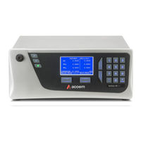
ACOEM Serinus 40 User Manual (258 pages)
Oxides of nitrogen analyser
Brand:
ACOEM
| Category:
Measuring Instruments
| Size: 14 MB
Table of Contents
Table of Contents
3
Manufacturer's Statement
13
Notice
13
Safety Information
14
Table 1 - Internationally Recognised Symbols
14
Important Safety Messages
15
Warranty
16
Service & Repairs
17
Product Compliance and Approvals
18
Manual Revision History
19
Table 2 - Manual Revision History
19
Introduction
21
Description
21
Specifications
21
Measurement
21
Precision/Accuracy
21
Calibration
22
Power
22
Operating Conditions
22
Communications
22
Physical Dimensions
23
Certifications
23
Nomenclature
24
Background/Theory
25
Measurement Theory
25
Figure 1 - Simple Pneumatic Diagram
26
Kalman Filter Theory
27
Instrument Description
27
Figure 2 - Major Components of Serinus 40
27
Calibration Valve Manifold
28
Auxiliary Valve Manifold
28
Delay Loop
28
Sample Filter Holder
28
Figure 3 - Calibration Valve Manifold
28
Figure 4 - Auxiliary Valve Manifold
28
Dryer
29
Figure 5 - Sample Filter Holder
29
Figure 6 - Dryer
29
Ozone Generator
30
2 To no Converter
30
Figure 7 - Ozone Generator
30
Figure 8 - no 2 to no Converter
30
Measurement Cell
31
Figure 9 - Measurement Cell
31
Figure 10 - PMT Assembly
31
Figure 11 - Reaction Cell
32
Figure 12 - Optical Bandpass Filter
32
Pneumatic Tubing
33
Main Controller PCA
33
Figure 13 - Pressure Sensor PCA
33
Figure 14 - Ecotech Tubing
33
Rear Panel
34
Figure 15 - Rear Panel
34
Communications
35
Figure 16 - Power ON/OFF Switch
35
Figure 17 - Communication Connections
35
Installation
37
Initial Check
37
Table 3 - List of Items Received
37
Figure 18 - Received Item
38
Figure 19 - Opening the Instrument - 1
39
Figure 20 - Opening the Instrument - 2
39
Figure 21 - Opening the Instrument - 3
39
Installation Notes
40
Figure 22 - Opening the Instrument - 4
40
Instrument Set-Up
41
Power Connections
41
Figure 23 - Instrument Rear Panel
41
Pneumatic Connections
42
Figure 24 - Connect Power Cord
42
Figure 25 - Turn on Power Switch
42
Figure 26 - Dust Plugs
43
Figure 27 - Remove Nut
43
Figure 28 - Ferrules Correct Orientation
43
Figure 29 - Replace Nut Loosely
44
Figure 30 - Insert Tube
44
Figure 31 - Tighten Nut
44
Communications Connections
45
Instrument Set-Up
46
Figure 32 - Installation of USB Memory Stick
46
Figure 33 - Switching the Battery ON/OFF
46
EPA Reference Set-Up
47
Type Approval Set-Up
48
Transporting/Storage
48
Figure 34 - Dust Plugs
49
Figure 35 - Packing Instruction
50
Operation
51
Warm-Up
51
Measurement
51
Table 4 - Measurements Times
51
General Operation Information
52
Keypad & Display
52
Figure 36 - Front Panel
52
Table 5 - Front Panel Buttons Function
53
Home Screen
54
Figure 37 - Home Screen
54
Menus & Screens
56
Quick Menu
57
Figure 38 - Quick Menu Screen
57
Main Menu
58
Figure 39 - Main Menu Screen
58
Analyser State Menu
59
Figure 40 - Analyser State Menu Screen
59
Status Menu
60
Figure 41 - Status Menu Screen
60
Temperature Menu
62
Figure 42 - Temperature Menu Screen
62
Pressure & Flow Menu
63
Voltage Menu
63
Figure 43 - Pressure & Flow Menu Screen
63
Figure 44 - Voltage Menu Screen
63
General Settings Menu
64
Figure 45 - General Settings Menu Screen
64
Measurement Settings Menu
65
Figure 46 - Measurement Settings Menu Screen
65
Calibration Menu
67
Figure 47 - Calibration Menu Screen
67
Pressure Calibration Menu
70
Figure 48 - Pressure Calibration Menu Screen
70
Service Menu
71
Figure 49 - Service Menu Screen
71
Diagnostics Menu
72
Figure 50 - Diagnostics Menu Screen
72
Digital Pots Menu
73
Figure 51 - Digital Pots Menu Screen
73
Internal Pump Menu (Option)
74
Figure 52 - Internal Pump Menu Screen
74
Valve Menu
75
Figure 53 - Valve Menu Screen
75
Tests Menu
77
Digital Input Test Menu
77
Figure 54 - Tests Menu Screen
77
Figure 55 - Digital Input Test Menu Screen
77
Digital Output Test Menu
78
Calculation Factors Menu
78
Figure 56 - Digital Output Test Menu Screen
78
Figure 57 - Calculation Factors Menu Screen
78
Communications Menu
80
Figure 58 - Communications Menu Screen
80
Data Logging Menu
81
Figure 59 - Data Logging Menu Screen
81
Serial Communication Menu
82
Figure 60 - Serial Communication Menu Screen
82
Analog Input Menu
83
Figure 61 - Analog Input Menu Screen
83
Analog Output Menu
84
Figure 62 - Analog Output Menu Screen
84
Digital Input Menu
85
Figure 63 - Digital Input Menu Screen
85
Digital Output Menu
86
Figure 64 - Digital Output Menu Screen
86
Table 6 - Digital Output States
87
Network Menu (Optional)
88
Figure 65 - Network Menu Screen
88
Bluetooth Menu
89
Figure 66 - Bluetooth Menu Screen
89
Trend Display Menu
90
Figure 67 - Trend Display Menu Screen
90
Chart
91
Figure 68 - Chart Screen
91
Advanced Menu
93
Figure 69 - Advanced Menu Screen
93
Hardware Menu
94
Figure 70 - Hardware Menu Screen
94
Parameter Display Menu
95
Figure 71 - Parameter Display Menu Screen
95
Communications
97
RS232 Communication
97
Figure 72 - Communication Ports
97
USB Communication
98
Figure 73 - Multidrop RS232 Cable Example
98
TCP/IP Network Communication (Optional)
99
Figure 74 - Example of Typical Network Setups
99
Reading Network Port Setup
100
Setting Network Port Setup
100
Figure 75 - Example of Network Menu Setup
100
Port Forwarding on Remote Modem/Router Setup
101
Setup Airodis to Communicate with Serinus
101
Figure 76 - Port Forwarding Example
101
Figure 77 - LAN Network Set-Up (Airodis)
101
Analog and Digital Communication
102
Analog Outputs
102
Figure 78 - WAN Network Set-Up (Airodis)
102
Analog Inputs
103
Digital Status Inputs
103
Digital Status Outputs
103
Figure 79 - Rear Panel PCA (Default Jumpers Highlighted)
104
Figure 80 - Analog & Digital I/O Individual Pin Descriptions
104
Logging Data
105
Configure Instrument Internal Logging
105
Using Airodis Software to Download Data
105
Connecting the Instrument to a PC
105
Figure 81 - Installing Driver Software (Device Manager)
106
Figure 82 - Update Driver Popup
106
Figure 83 - Update Driver Popup (Directory Location)
107
Figure 84 - Installing Driver Confirmation Prompt
107
Installing Airodis
108
Figure 85 - Successful Driver Installation
108
Configuring Airodis
109
Figure 86 - Airodis Workspace Manager
109
Figure 87 - Adding a New Station
109
Figure 88 - New Station Connection
110
Table 7 - New Station Setup
110
Figure 89 - Station Configuration (Channel List)
111
Figure 90 - Error Status Notification
111
Figure 91 - Downloading Data
112
Figure 92 - Download Data Status
112
Figure 93 - Data Visibility
113
Figure 94 - Exporting Data
113
Serinus Remote App/Bluetooth
114
Figure 95 - Data Download Complete
114
Installation
115
Connecting to the Instrument
115
Figure 96 - Downloading the App from Google Play Store
115
Figure 97 - Bluetooth Pairing Request
115
Instrument Control
116
Figure 98 - Showing or Hiding the Numpad
116
Real-Time Plot
117
Figure 99 - Switching Analysers
117
Download
118
Figure 100 - Real-Time Plot
118
Get Parameters
119
Figure 101 - Plot of Downloaded Data
119
Preferences
120
Figure 102 - Directory Settings
120
Figure 103 - Logs Format
120
Figure 104 - Colour Theme Settings
121
Calibration
123
Overview
123
Figure 105 - Example of a Calibration System
123
Pressure Calibration
125
Full Pressure Calibration (Two Point Calibration)
125
Figure 106 - Full Pressure Calibration Set-Up
126
Figure 107 - Full Pressure Calibration Set-Up (Ambient)
126
Pressure Calibration (Ambient Only)
127
Pressure Calibration (Internal Pump Option Only)
127
Figure 108 - Ambient Pressure Calibration Set-Up
127
Figure 109 - Pressure Calibration (Internal Pump Option Only) Set-Up
128
Zero Calibration
129
Calibration Port
129
Sample Port
129
Background Air Port
130
Span Calibration
130
Calibration Port with Multiple Gains Disabled
131
Sample Port with Multiple Gains Disabled
131
Sample Port with Multiple Gains Enabled
132
Manual Instrument Gain and Offset Adjustments
133
Precision Check
133
Multipoint Precision Check
134
2 To no Converter Efficiency
135
Figure 110 - Multipoint Calibration Results Example
135
Single Point no to no Converter Efficiency Check
136
Multipoint no to no Converter Efficiency Adjustment
137
High Pressure Zero/Span Valve (Option)
138
Single Pressurised Calibration Option
138
Figure 111 - Single High Pressure Calibration Option
138
Dual Pressurised Calibration Option
140
Figure 112 - Dual High Pressure Calibration Option
140
Service
143
Additional Safety Requirements for Service Personnel
143
Maintenance Tools
143
Figure 113 - Minifit Extraction Tool - (PN: T030001)
143
Maintenance Schedule
144
Figure 114 - Orifice/Sintered Filter Removal Tool - (PN: H010046)
144
Figure 115 - Leak Test Jig - (PN: H050069)
144
Figure 116 - Air Monitoring Test Equipment Kit (AMTEK) - Customisable
144
Table 8 - Maintenance Schedule
145
Maintenance Procedures
146
Particulate Filter Replacement
146
Figure 117 - Remove Compression Nut
146
Figure 118 - Remove Retaining Ring
146
Figure 119 - Remove Filter Sealing Cap
147
Figure 120 - Particulate Filter
147
Clean Chassis Fan Filter
148
Figure 121 - Avoid to Touching Particulate Filter Paper
148
Figure 122 - Compression Fitting Elbow Direction
148
DFU Replacement
149
Leak Check
149
Figure 123 - Remove Filter Casing and Filter
149
Figure 124 - DFU Filter
149
Figure 125 - Leak Test Jig on Exhaust Port
150
Figure 126 - Connect Vacuum Source
150
Figure 127 - Stop Valve (Bypass Pump)
152
Figure 128 - Stop Valve (Sample Pump)
153
Clean Pneumatics
154
Replacing the PMT Desiccant Pack
154
Cleaning the Reaction Cell
155
Figure 129 - Removing the Desiccant Pack
155
Figure 130 - Electrical Tape
156
Figure 131 - Remove Reaction Cell
156
Figure 132 - Cover the PMT Window
157
Figure 133 - Place the Black Electrical Tape
157
Figure 134 - Optical Bandpass Filter Removal and Cleaning
157
Ozone Generator Maintenance
158
Figure 135 - Replace Reaction Cell
158
Figure 136 - Remove Ozone Generator from Instrument
159
Figure 137 - Remove the Screw
159
Figure 138 - Remove the Screw
160
Figure 139 - Remove White Tube Block Fastener
160
Pressure Sensor Check
161
Figure 140 - Disassemble Glass Tube
161
Figure 141 - Test Point Location
162
Figure 142 - Typical Test Point Reading of Cell Pressure with Vacuum Connected to Exhaust Port
162
Bootloader
163
Display Help Screen
163
Communications Port Test
163
Figure 143 - Typical Test Point Reading of Manifold Pressure Sensor
163
Updating Firmware
164
Erase All Settings
164
Start Analyser
164
Troubleshooting
165
Table 9 - Troubleshoot List
165
Flow Fault
168
Figure 144 - Flow Fault Diagnostic Procedure
168
Noisy/Unstable Readings
169
Figure 145 - Noisy or Unstable Readings Troubleshooting Flow Chart
169
Converter Temperature Failure
170
Figure 146 - Converter Alarm Troubleshooting Flow Chart
170
Auxiliary Valve Manifold Temperature Failure
171
Figure 147 - Valve Manifold Temperature Alarm Troubleshooting Flow Chart
171
Reaction Cell Temperature Failure
172
Figure 148 - Reaction Cell Temperature Failure Troubleshooting Flow Chart
172
USB Memory Stick Failure
173
Figure 149 - USB Memory Stick Failure
173
Ecotech Service Support Files
174
Figure 150 - USB Memory Stick File Structure
174
Optional Extras
177
Dual Sample Filter (PN: E020100)
177
Figure 151 - Dual Filter Option Installed
177
Table 10 -Dual Sample Filter Parts Added
177
Test Lamp (PN: E020103)
178
Network Port (PN: E020101)
178
Table 11 -Test Lamp Parts Added
178
Table 12 - Test Lamp Parts Removed
178
Table 13 - Network Port Parts Added
178
Table 14 - Network Port Parts Removed
178
Hardware Setup
179
Sample Dryer (PN: E020118)
179
Rack Mount Kit (PN: E020116)
179
Table 15 - Sample Dryer Parts Added
179
Table 16 -Rack Mount Kit Parts Added
179
Figure 152 - Separate Rack Slides
180
Figure 153 - Assemble Inner Slide on Chassis
180
Figure 154 - Rack Mount Ears Fitted to Instrument
181
Figure 155 - Attach Rack Mount Adaptors to Outer Slides
181
Figure 156 - Test Fit the Rack Slide Assembly into Your Rack
182
Figure 157 - Attach Slides to Front of Rack
182
Internal Pump (PN: E020104)
183
Hardware Setup
183
Internal Pump Additional Components
183
Figure 158 - Slide Clips
183
Table 17 - Internal Pump Additional Components
183
Pressure Calibration Internal Pump Option
184
Leak Check Internal Pump Option
184
Pump Control
184
Metric Fittings Kit (PN: E020122)
184
High Pressure Zero/Span Valves
185
High Level Instrument (PN: E020113)
185
High Level Specifications
185
Table 18 - High Level Instrument Parts Added
185
Table 19 - High Level Instrument Parts Removed
185
Internal Zero and Span (PN: E020134)
186
IZS Specifications
187
Figure 159 - IZS Specific Internal Components Diagram
187
Table 20 - IZS Parts Removed
187
Table 21 - IZS Parts Added
187
Figure 160 - Typical Permeation Tube and Chamber Dimensions (Units in MM)
188
IZS Setup
189
IZS Transporting/Storage
190
Figure 161 - Permeation Tube Removal
190
IZS Calibration
191
IZS Service and Maintenance
192
Table 22 - IZS Annual Maintenance Kit - (PN: E020212)
192
Trace Level Instrument (PN: E020119)
194
Trace Specifications
194
Table 23 - Trace Parts Removed
194
Trace Setup
195
Table 24 - Trace Parts Added
195
Trace Operation
196
Trace Default Values
196
Trace Calibration Guidelines
197
Table 25 - Trace Parameter Value Changes
197
Trace Service and Maintenance
198
Table 26 - Maintenance Schedule
198
Parts List and Schematics
199
Serinus Accessories Kit
199
Maintenance Kit
199
Table 27 - Serinus Accessories Kit - (PN: H010136)
199
Table 28 - Annual Maintenance Kit - (PN: E020203-01)
199
Consumables
200
Table 29 - Consumables
200
Instrument Parts List
201
Table 30 - Spare Parts List (Main Components)
201
Table 31 - Spare Parts List (Cables)
203
Table 32 - Spare Parts List (O-Rings)
203
Table 33 - Spare Parts List (Fittings)
203
Table 34 - Spare Parts List (Miscellaneous)
204
Optional Extras Spare Part List
205
Table 35 - Spare Parts List (Shipping)
205
Table 36 - Spare Part List (Test Lamp)
205
Table 37 - Spare Part List (Sample Dryer)
206
Table 38 - Spare Part List (Internal Pump)
206
Table 39 - Spare Part List (Metric Fittings Kit)
206
Table 40 - Spare Part List (High Pressure Zero/Span Valves)
206
Table 41 - Spare Part List (High Level Instrument)
207
Table 42 - Spare Part List (IZS)
207
Table 43 - Spare Part List (Trace Level Instrument)
207
Plumbing Schematic - (PN: D020002)
208
Internal Pump Plumbing Schematic - (PN: D020063)
210
High Level Plumbing Schematic - (PN: D020024)
212
Trace Level Plumbing Schematic - (PN: D020065)
214
Sample Dryer Plumbing Schematic - (PN: D020064)
216
IZS Plumbing Schematic - (PN: D020052)
218
Block Wiring Schematic - (PN: D020103-01)
220
IZS Block Wiring Schematic - (PN: D020122-01)
221
Measurement Cell and Reaction Cell Exploded View - (PN: H011200)
222
Auxiliary Valve Manifold Assembly Exploded View - (PN: H011300)
223
Calibration Valve Manifold Assembly Exploded View - (PN: H010013-01)
224
Ozone Generator Assembly Exploded View - (PN: H011107)
225
IZS Calibration Valve Manifold Assembly Exploded View - (PN: H010056)
226
Permeation Oven Assembly Exploded View - (PN: H012170)
227
Valve Assembly Exploded View - (PN: H010042)
228
Sample Filter Holder Assembly - (PN: H010160)
229
High Pressure Valve Exploded View - (PN: H050043)
230
Converter Assembly - (PN: H011105)
231
Internal Pump Assembly - (PN: H011140)
232
Dryer Assembly - (PN: H011106)
233
Flow Block Assembly - (PN: H013165)
234
Table 44 - Packet Format
235
Table 45 - Example: Primary Gas Request
235
Appendix A. Advanced Protocol
235
Command Format
235
Table 46 - Example: Primary Gas Response
236
Table 47 - Example: Primary Gas Response (Continued)
236
Table 48 - List of Errors
236
Commands
236
Table 49 - Example: Get IEEE Response Data
237
Table 50 - Advanced Protocol Parameter List
238
List of Parameters
238
Appendix B. EC9800 Protocol
249
Command Format
249
Commands
249
Table 51 - Bayern-Hessen Data
251
Appendix C. Bayern-Hessen Protocol
251
Command Format
251
Table 52 - Block Check Operation
252
Commands
252
Table 53 - Status Bit Map
253
Table 54 - Failure Bit Map (Positive Logic)
253
Appendix D. Modbus Protocol
255
Command Format
255
Commands
255
Table 55 - Modbus Error Codes
257
Advertisement
Advertisement
Related Products
ACOEM Serinus 44
ACOEM 1-0897 T21
ACOEM 1-1063 P1
ACOEM 1-1216 M7
ACOEM 1-1217 S7
ACOEM 1-1263 M9
ACOEM 1-1264 S9
ACOEM 1-1278 M10
ACOEM 1-1279 S10
ACOEM AT Series
ACOEM Categories
Measuring Instruments
Security System
Tools
Laboratory Equipment
Samplers
More ACOEM Manuals
Login
Sign In
OR
Sign in with Facebook
Sign in with Google
Upload manual
Upload from disk
Upload from URL