Table of Contents
Advertisement
Quick Links
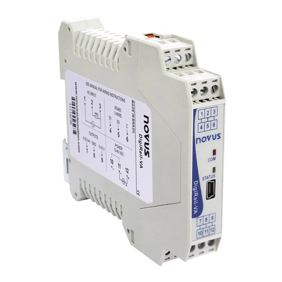
DigiRail-VA
USER GUIDE −
V1.0x G
1.
MAIN FEATURES ......................................................................................................................................................... 2
2.
SPECIFICATIONS ........................................................................................................................................................ 3
3.
INSTALLATION AND OPERATION ................................................................................................................................... 4
3.1
MECHANICAL INSTALLATION .................................................................................................................................. 4
3.1.1
DIMENSIONS ................................................................................................................................................ 4
3.2
ELECTRICAL INSTALLATIONS AND OPERATION ........................................................................................................ 4
3.2.1
INSTALLATION RECOMMENDATIONS ............................................................................................................... 5
3.2.2
POWER SUPPLY ............................................................................................................................................ 5
3.2.3
RS485 .......................................................................................................................................................... 5
3.2.4
USB INTERFACE ............................................................................................................................................ 5
3.2.5
AC INPUTS ................................................................................................................................................... 6
3.2.6
4-20 MA OUTPUT ........................................................................................................................................... 8
3.2.7
0-10 V OUTPUT .............................................................................................................................................. 8
4.
INDICATOR LIGHTS (LEDS) ......................................................................................................................................... 10
5.
USB DRIVER INSTALLATION ....................................................................................................................................... 11
5.1
WINDOWS 11 ...................................................................................................................................................... 11
6.
HOW TO SET AND SELECT A SERIAL PORT (COM) − WINDOWS ...................................................................................... 13
7.
CONFIGURATION SOFTWARE ..................................................................................................................................... 14
7.1
INITIAL CONFIGURATION AND SOFTWARE INSTALLATION ........................................................................................ 14
7.2
EQUIPMENT FIRMWARE UPDATE .......................................................................................................................... 14
8.
MODBUS COMMANDS AND REGISTERS TABLE ............................................................................................................. 15
8.1
SUPPORTED MODBUS COMMANDS ....................................................................................................................... 15
8.1.1
READ HOLDING REGISTERS - 03H ................................................................................................................ 15
8.1.2
WRITE SINGLE REGISTER - 06H .................................................................................................................... 15
8.1.3
WRITE MULTIPLE REGISTERS - 16H .............................................................................................................. 15
8.2
HOLDING REGISTERS TABLE ................................................................................................................................ 15
8.3
DETAILS ABOUT SOME REGISTERS ....................................................................................................................... 16
8.3.1
REGISTERS 20 TO 28 - MEASUREMENT VALUE IN INTEGER FORMAT ................................................................ 16
8.3.2
REGISTERS 200 AND 201 - SERIAL NUMBER................................................................................................... 16
8.3.3
REGISTER 202 - FIRMWARE VERSION ........................................................................................................... 16
8.4
FLOATING POINT FORMAT .................................................................................................................................... 16
9.
WARRANTY .............................................................................................................................................................. 17
NOVUS AUTOMATION
1/17
Advertisement
Table of Contents

Related Manuals for Novus DigiRail-VA


Summary of Contents for Novus DigiRail-VA
-
Page 1: Table Of Contents
DigiRail-VA USER GUIDE − V1.0x G MAIN FEATURES ................................. 2 SPECIFICATIONS ................................ 3 INSTALLATION AND OPERATION ........................... 4 MECHANICAL INSTALLATION ..........................4 3.1.1 DIMENSIONS ..............................4 ELECTRICAL INSTALLATIONS AND OPERATION ......................4 3.2.1 INSTALLATION RECOMMENDATIONS ....................... 5 3.2.2 POWER SUPPLY ............................5 3.2.3... -
Page 2: Main Features
DigiRail-VA MAIN FEATURES DigiRail-VA is a transmitter and signal conditioner related to alternating current (single-phase), capable of measuring the following quantities on the True-RMS: Voltage • Current • Active, reactive, and apparent power • Frequency • Power Factor • The measured values can be read out via the RS485/Modbus RTU interface. In addition, they can be retransmitted simultaneously via the 4-20 mA and 0-10 V outputs. -
Page 3: Specifications
DigiRail-VA SPECIFICATIONS Power Supply: 10 to 40 Vdc. Max consumption: approx. 40 mA @ 24 V; plus 20 mA when you used a 4-20 mA output. Peaks of up to 20 mA can also occur when the equipment is sending data through the RS485 interface. -
Page 4: Installation And Operation
Dimensions 3.2 ELECTRICAL INSTALLATIONS AND OPERATION DigiRail-VA has connectors for the power supply, for the inputs for AC measurement, for the output for analog transmission and for the RS485 serial communication interface. Furthermore, it has a USB mini-B interface. Figure 2 –... -
Page 5: Installation Recommendations
• Section of used wires: minimum gauge of 0,14 mm². 3.2.2 POWER SUPPLY The terminals 11 and 12 (or 10 and 12) are intended for the power supply for DigiRail-VA. The polarity of the power supply must be carefully observed and the voltage level. -
Page 6: Ac Inputs
COMMOM Table 2 – Terminals The current measurement is done by an internal shunt resistor, so that the DigiRail-VA is connected in series with the load to be measured. The following figure illustrates the device connected to the measuring circuit. - Page 7 Figure 06. Measurement of power factor there need voltage and current being measured by DigiRail-VA, it is a calculated value based on the phase shift of these two quantities. If one of the values of the voltage or current is near zero, the calculated value of power factor may result in wrong values. That is why the DigiRail-VA inhibits power factor measurement when the voltage or current showing small values, typically 0.1 % of full scale.
-
Page 8: Ma Output
Therefore, you should be careful when using the 4-20 mA and 0-10 V outputs to send signals to other devices that are powered from the same source as DigiRail-VA. If the 4-20 mA and 0-10 V outputs are used at the same time, you can have problems if both are read by the same device and if the device does not have isolated inputs. - Page 9 Therefore, you should be careful when using the 4-20 mA and 0-10 V outputs to send signals to other devices that are powered from the same source as DigiRail-VA. If the 4-20 mA and 0-10 V outputs are used at the same time, you can have problems if both are read by the same device and if the device does not have isolated inputs.
-
Page 10: Indicator Lights (Leds)
Possible hardware issues. Table 3 – Status LED Communication LED: It indicates that an RS485/Modbus communication is in progress. Blinks whenever the DigiRail-VA is sending a Modbus frame via the RS485 interface (in response to a command). NOVUS AUTOAMTION 10/17... -
Page 11: Usb Driver Installation
The steps for installing the driver are shown below. WINDOWS 11 1. Plug the DigiRail-VA into a USB port on your computer. Windows will recognize it as a USB Serial Device (COM X), a generic device. You will need to manually install the device driver. - Page 12 DigiRail-VA 4. Ask to “Browse my computer for drivers”, indicating the path to the folder where the equipment drivers are (files downloaded from NOVUS' website, available on the product page): Figure 15 – Searching drivers 5. Wait for the installation to finish. After this, the device will be recognized by your computer, as you can see in the “Device Manager”: Figure 16 –...
-
Page 13: How To Set And Select A Serial Port (Com) − Windows
HOW TO SET AND SELECT A SERIAL PORT (COM) − WINDOWS The DigiRail-VA serial port is determined by the operating system moments after you plug in the device. To identify or change the COM port associated with the DigiRail-VA, follow the path below: Control Panel / System / Hardware / Device Manager / Ports (COM &... -
Page 14: Configuration Software
In the next window, select the serial port and configure the other communication parameters. After applying the communication configuration, the system will be able to read the DigiRail-VA configuration, making the search in the button located in the lower left corner of the main window. -
Page 15: Modbus Commands And Registers Table
MODBUS COMMANDS AND REGISTERS TABLE DigiRail-VA accepts some Modbus commands that are sent to its Modbus’ own address, operating as a network slave. Commands forwarded to other slaves (routing) will be sent in a transparent way. The following listed Modbus RTU commands (functions) are implemented, and these are interpreted by DigiRail-VA. -
Page 16: Details About Some Registers
If the version is “1.00” it will read the value as “100”. If the version is "2,04" it will read it as "204". FLOATING POINT FORMAT DigiRail-VA uses floating point values of single precision (32 bits) according to the IEEE-754 standard (ANSI / IEEE Standard for Binary Floating- Point Arithmetic). -
Page 17: Warranty
DigiRail-VA WARRANTY Warranty conditions are available on our website: www.novusautomation.com/warranty. NOVUS AUTOAMTION 17/17...
Need help?
Do you have a question about the DigiRail-VA and is the answer not in the manual?
Questions and answers