
Subscribe to Our Youtube Channel
Related Manuals for Cantek EM 12


Summary of Contents for Cantek EM 12
- Page 1 Operations Manual www.cantekamerica.com EM 12 End Matcher Please ensure you have your serial number available when contacting us for parts or service. Cantek America Inc. | 1.888.982.2683 | Parts: sales@cantekamerica.com | Service: service@cantekamerica.com...
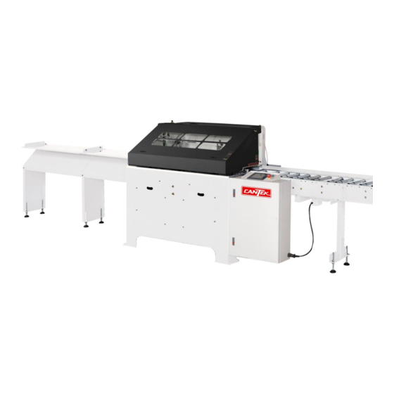
- Page 2 INTRODUCTION The END MATCHER is a pneumatically operated machine developed specifically for automatic cutting of grooves across the end of timber and floorboards in particular. The machine is universally renowned for the repetitive clean cut across the ends of the timber and the speed that the unit is capable of. The END MATCHER has been developed over 20 years to meet the needs of the timber industry and contains many unique features that allows easy access for tool changes and complies with today’s rigorous safety compliance requirements.
-
Page 3: Specification
SPECIFICATION EM-10 EM-12 MODEL ELECTRICAL: SUPPLY 380~415/400-480V, 3PH, 50/60HZ CONTROL 24VDC CONNECTED LOAD 9.2KW. MOTOR: CUTTER HEADS 2 x 5.5KW(7.5HP), 3PH. FEED 0.75KW(1.0HP), 3PH CUTTER DRIVE 0.37KW(0.5HP), 3PH CAPACITY: MIN.=40 MIN.=40 WIDTH(mm) MAX.=250 MAX.=300 MIN.=10 THICKNESS(mm) MAX.=35 MIN. BOARD LENGTH 270mm MAX. - Page 4 Cantek America. This includes the addition of control devices for external machinery. (h) The following data is to be entered and a copy supplied to Cantek America within seven (7) days of the machine commencing operation in the plant.
- Page 5 SAFETY SAFETY PROCEDURES AND CONSIDERATIONS: To ensure safe working conditions, persons operating and assisting with the operation of this machine must ensure that they read and fully understand the instructions given within this manual and have received sufficient raining in the use of the machine and the safety aspects to be observed. Note: Persons under the age of 18 years must not operate the machine except during the course of training under the supervision of a trained operator.
- Page 6 TRANSPORT The Cantek America End Matcher is a precision machine and great care must be taken during loading, unloading, and placing into position. The machine can be lifted using a forklift or crane. The weight is about 1050 Kg. Ensure the Endprofiler is properly secured and balanced before lifting.
- Page 7 COMPONENTS A. CONTROLS: Once the emergency stop button is pressed, the machine becomes inoperable until it is released again- twist the button to release. The Start/Reset button is used to reset the machine or to start the machine, this depends on the mode and state the machine is in.
- Page 8 B.MATERIAL THICKNESS ADJUSTMENT The vertical/roller plate is mounted on two cylinders, refer to Fig. 4, which allows for the plate to be lifted up if a splinter, bowed board, or something else has jammed up the machine. If a jam occurs, stop the feed rollers and put the machine into manual mode.
- Page 9 Once the board thickness changes, the levelling bolts will have to be adjusted. The levelling bolts are designed to ensure the clamp plate is level (horizontal) when in the retracted position. To check if the clamp plate is level, retract the clamp and the gap between the table and clamp plate should be the same at the front and rear (parallel).
- Page 10 C.MATERIAL WIDTH ADJUSTMENT: Material width adjustment is done by moving the clamp bar to the appropriate set of adjusting bolt holes. The holes are at 15 mm increments. NOTE: For boards <19mm thick, replace clamp bar with the thinner one supplied, designed for boards between 10-19mm thick.
- Page 11 D.CUTTING ADJUSTMENTS: The amount of material removed with each cut can be controlled by the material adjusting bolts on the pusher stop mechanism. When these bolts are adjusted, the limit switches on the air cylinders should be checked (cannot be seen, but arrows point to the position on the cylinder). The speed of the cut can be adjusted at anytime via the Touchscreen, refer to “Touchscreen Manual”.
- Page 12 E.FEED SYSTEM: The Feed is driven by a 0.75kW 3 phase motor, and the connecting belt is an A-24 V-belt. For a more comprehensive illustration of the feed system, refer to drawings 300-03V and 300-04V. The feed system is a lubrication free drive system which requires minimum maintenance. The worm wheels are a wearing component and should be checked regularly for wear, and if wear is present, they might need to be changed.
- Page 13 F. Sensors System: Sometimes the sensors will be loosened during shipment or movement. And it sometimes will make the setup go wrong and reflect on the PLC. Please check sensors first if the PLC does not work rightly. The light of this sensor will only shine when working pieces passes. If the light is keeping shining, please adjust via the hole for its sensitivity.
- Page 14 In a normal state, one light will keep shining and another will only shine when working piece passes. If both two are keeping shining, please adjust via the hole. In a normal state, the light of sensor will always shine but go out when pressing the working piece. Please adjust the screw if it does not work rightly.
- Page 15 OPERATING INSTRUCTIONS OPERATING SEQUENCE: The first board enters the machine and passes over the wood infeed sensor, activating the Infeed Clamp delay timer - the timer should be set so the board just makes it to the stop (to prevent the rollers rubbing) but doesn’t clamp too early.
-
Page 16: Replacement Parts
REPLACEMENT PARTS CUTTER TIPS: Once the initial Endmatch sizes have been set, it is normally not necessary to remove the cutter heads to change the tips. Simply switch the machine to MANUAL and bring the cutter heads forward, so that the cutters can be easily accessed to change or rotate the tips. -
Page 17: Maintenance
MAINTENANCE The maintenance of any machine is a vital ingredient to ensuring the longevity and performance of the machine. A maintenance schedule should be developed and followed by a qualified person, or someone who has been trained to perform such tasks. The maintenance schedule should include the following aspects;... -
Page 18: Common Components
COMMON COMPONENTS CUTTER SPINDLES: DRIVE BELTS ......SPZ 800 (60hZ) or SPZ 875 (50Hz) BEARINGS ........6010 ZZ SPINDLE NUTS ......40 mm X 1, 5 mm pitch Compatible with Weinig. CUTTER CARRIAGE: BEARINGS ........40mm LINEAR BEARING IMPACT PAD ......... POLYURETHANE IMPACT PAD CUTTER DRIVE ...... - Page 19 OPERATION INTRUCTIONS OF SPIRAL CUTTERHEAD A. THE ADVANTAGE OF THE DISOPSABLE AND GRIND ABLE SPIRAL CUTTER: With high strength, low noise, heavy duty cutting, low horsepower, long life and low cost. Grinding one side, four sides of edge can be use. If the edge is broken by the debris, then change to another edge.
- Page 20 SPIRAL CUTTER GRAPH EXPLANATION: A1~A5 The knives has dirty and incorrect combination would make it rift. A-4 If air screw driver lock lower 6KG cause knife trough seals of wood chip from chink pressure to knives broken. A-5 The wrench pressure up to 6KG, it will cause blade or screw broken, this is due to the T.C. blade is the hardest, so when cutting very high speed, the screw instead of blade cutter head have unusual voice or shake when cutting and cause cutting balance is nor well, please stopped to insect the machine.
- Page 21 EM-10 / EM-12 This manual describes the machine in current produce on. We reserve the right to change the specifications without notice.
- Page 22 E. NOTE: 1. The running speed of cutter is high and designed to heavy and fast cutting. So it is very important to keep the completeness of whole cutter. Never slash or crash the cutterhead, or it will lose its balance, make the cutterhead sway and effect the cutting result. 2.
- Page 23 TOUCH SCREEN MANUAL EM-10 / EM-12 This manual describes the machine in current produce on. We reserve the right to change the specifications without notice.
- Page 24 HOME PAGE DISPLAY key : Press this key for entering into automatic operation mode. EM-10 / EM-12 This manual describes the machine in current produce on. We reserve the right to change the specifications without notice.
- Page 25 HOME PAGE DISPLAY key : Press this key for entering into feed through mode. This function is used when wood jam occurs. EM-10 / EM-12 This manual describes the machine in current produce on. We reserve the right to change the specifications without notice.
- Page 26 HOME PAGE DISPLAY key : Press this key for entering into manual operation mode. EM-10 / EM-12 This manual describes the machine in current produce on. We reserve the right to change the specifications without notice.
- Page 27 LENGTH SETTING DISPLAY Press the "Auto" key on the home page display, then the screen will show a length setting display as above. This display allows the operator to set total length of cut and displays the current length conditions. EM-10 / EM-12 This manual describes the machine in current produce on.
- Page 28 LENGTH SETTING DISPLAY 0.00 (1) The operator may set his desired total length of cut. (2) Once the setting total length reaches, the machine will stop and the buzzer sounds to notify the operator. 0.00 (3) To set the total length of cut, press the numeric column "set ft"...
- Page 29 LENGTH SETTING DISPLAY Actual 0.00 (1) This column displays the actual length has been cut up to now from the begining of operation. (2) This column only provides display. The value shown on this column can't be set. However, reset value (zero setting) is allowed. 0.00 (3) To set zero on this column, press the numeric column "Actual ft"...
- Page 30 LENGTH SETTING DISPLAY pieces (1) This column displays the total pieces of wood has been cut up to now from the begining of operation. (2) This column only provides display. The value shown on this column can't be set. However, reset value (zero setting) is allowed. (3) To set zero on this column, press the numeric column "Pieces "...
- Page 31 LENGTH SETTING DISPLAY jams (1) This column displays times of wood jamming up to now during the machine has been operated. (2) The column only provides display. The value shown on this column can be reset (zero setting). (3) To set zero on this column, press the numeric column "Jams "...
- Page 32 LENGTH SETTING DISPLAY piece Length inches 0.00 (1) This column displays length of each piece of wood. (2) Wood length is measured by an encoder. (3) When the front end of wood moves to the sensor (2) position and the sensor is sensed, the encoder will start to count the wood length.
- Page 33 LENGTH SETTING DISPLAY Home Press this key for displaying the home page display. HOME pAGE dISpLAY Totals Press this key for displaying the "Totals" display, shown as below. EM-10 / EM-12 This manual describes the machine in current produce on. We reserve the right to change the specifications without notice.
- Page 34 LENGTH SETTING DISPLAY Set up Press the "Setup" key, then a SETTIng DISPLAy-PAgE1 will show as below : SETTING dISpLAY - pAGE 1 (1) The setting display includes two pages. (2) Press the "Page 2" key on the SETTING DISPLAY-PAGE 1, then the screen will display the PAGE 2 shown as below: SETTING dISpLAY - pAGE 2 EM-10 / EM-12...
- Page 35 LENGTH SETTING DISPLAY Last piece (1) This key is used to perform cutting for the last piece of wood and move it out of the machine. (2) This key is effective only when keeping pressing it for 3 seconds. (3) When this key is continuously pressed for 3 seconds, motion sequences are: The rear spindle moves forward for cutting →...
-
Page 36: Setting Display
SETTING DISPLAY - PAGE 1 Press the "Setup" Key on the "LENGTH SETTING dISpLAY", then a setting display-page 1 will show as above. In Feed Speed (1) This column allows the operator to set feed speed of the feed rollers, according to wood material. - Page 37 SETTING DISPLAY - PAGE 2 Press the "page 2" Key on the "SETTING dISpLAY-pAGE 1", a "SETTING dIpLAY-pAGE 2" will display as above. Conveyor delay 0.00 (1) This key is used for setting the infeed conveyor running start time. (2) When the front spindle finish cutting, and returned to its home postion. The front clamping plate raises.
- Page 38 SETTING DISPLAY - PAGE 2 In clamp 0.00 (1) This key is used to set the distance which the wood will move forward. When the front edge of wood is detected by the sensor (1) located under the second rubber feed roller, distance calculation starts. (2) For example, if you set 100mm, the wood will move 100mm further from the sensor (1).
- Page 39 SETTING DISPLAY - PAGE 2 Length Comp. inch 0.00 (1) When you set a value on the Out clamp mm, generally the wood can't move and position at the accurate position as you set. This is caused by some factors, and that's why you need to make length compensation to achieve an accurate positioning of wood.
- Page 40 SETTING DISPLAY - PAGE 2 (3) INCORRECT POSITIONING OF WOOD • This figure shows the wood moves over. In this case, the pusher can't touch the tail end of wood. rEAr CuTTEr FrONT GuArd INCORRECT POSITIONING OF WOOD puSHEr WOOd MOvES OvEr TAIL ENd OF WOOd •...
- Page 41 SETTING DISPLAY - PAGE 2 (4) INCORRECT POSITIONING OF WOOD • This figure shows the wood moving distance is insufficient. In this case, the wood positions on the pusher. This causes the pusher can't touch the tail end of wood. WOOd INCPRRECT POSITIONING...
- Page 42 SETTING DISPLAY - PAGE 2 Metric/Imperial This key is used for changing metric and imperial size display. (1) Press this key one time for metric size display. (2) Press this key again for inch size display. EM-10 / EM-12 This manual describes the machine in current produce on. We reserve the right to change the specifications without notice.
- Page 43 SETTING DISPLAY - PAGE 2 Auto Press this key, then a length setting display (Auto mode) will show as below: page 1 Press this key for displaying the "SETTIng DISPLAy-PAgE1" as below: EM-10 / EM-12 This manual describes the machine in current produce on. We reserve the right to change the specifications without notice.
- Page 44 SETTING DISPLAY - PAGE 2 diagnostics In case a trouble occurs, the operator may press the "Diagnostics" key to Diagnostics show the display as below: prox Prox Press the key, a display will show as below: On the prox. display, the operator may check sensing condition of all proximity sensors on the machine.
- Page 45 FEED THRU DISPLAY EM-10 / EM-12 This manual describes the machine in current produce on. We reserve the right to change the specifications without notice.
- Page 46 FEED THRU DISPLAY 1. Press the "Feed Thru" Key on the home page, then the screen will show the "Feed Thru" display as below: 2. In case wood jams during operation, and you need to remove the wood. Then the "Feed Thru" function should be applied. 3.
-
Page 47: Manual Mode Display
MANUAL MODE DISPLAY Press the "Manual" key on the home page display, then the screen will show a "Manual Mode" display as above. rEAr CLAMp. (1) This key is used for raising and lowering the rear clamp, that releases or holds down the wood. - Page 48 MANUAL MODE DISPLAY FrONT CLAMp This key is used for raising and lowering the front clamp that releases or holds down the wood. (1) Press the key, the front clamp will raise up to release wood. (2) Press the key again, the front clamp will lower to press the wood. At this time, the key will light on.
- Page 49 MANUAL MODE DISPLAY puSHEr (1) After tenon has been cut by the front spindle, then the pusher will push the wood to the rear spindle for cutting mortise. (2) In manual operation mode, the operator may press key to enable the pusher to move the wood forward.
- Page 50 MANUAL MODE DISPLAY (1) When this key displays "ok", it means the machine is under normal condition and ready for operation. (2) In case there is any abnormal condition, this key will display "disable". It means the machine is not ready for operation. LIFT (1) This key is effective only in manual operation mode.
-
Page 51: Diagnostics Display
DIAGNOSTICS DISPLAY When the Diagnostics key is pressed, the screen will show a diagnostics display as above. The operator may understand the trouble condition through this display. description The error message will display on this column. Mode Stage Track No. Home Press this key to return to home page display. - Page 52 TOTALS DISPLAY Press the "Totals" Key, then a dispaly will show as below: Total Length 0.00 (1) This column displays the total length of wood has been produced up to now since the machine has been operated. (2) The value displayed on this column can't be changed but can be reset. Total Bits (1) This column displays the total clamping times up to now since the machine has been operated.
- Page 53 TOTALS DISPLAY Total Cuts (1) This column displays the total cutting cycles up to now since the machine has been operated. (2) The value displayed on this column can't be changed but can be reset. EM-10 / EM-12 This manual describes the machine in current produce on. We reserve the right to change the specifications without notice.
-
Page 54: Numeric Keypad Window
NUMERIC KEYPAD WINDOW (1) When you press numeric position on any setting column, this numeric keypad window will appear. (2) The operator may use the numeric keypad window to set, change and reset value shown on the displayed value. (3) Press your desired numeric keys, then press "ENT" key for entering the value.
Need help?
Do you have a question about the EM 12 and is the answer not in the manual?
Questions and answers
Do you have a troubleshooting manual for the EM-12 endmatcher?
The context mentions an "EM12 Manual" but does not specify if it is a troubleshooting manual.
This answer is automatically generated