Table of Contents
Advertisement
Quick Links
Advertisement
Table of Contents

Subscribe to Our Youtube Channel
Related Manuals for Cantek JEN-60


Summary of Contents for Cantek JEN-60
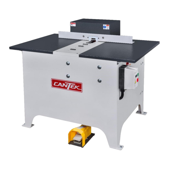
- Page 1 Operations & Parts Manual www.cantekamerica.com JEN-60 Drawer Notcher Please ensure you have your serial number available when contacting us for parts or service. Cantek America Inc. | 1.888.982.2683 | Parts: sales@cantekamerica.com | Service: service@cantekamerica.com...
-
Page 2: Table Of Contents
SETUP ROUTINE MAINTENANCE . 9~11 CHANG DRAWING NOTCH SIZE ..12 DRILL HEIGHT GAUGE 13~14 JEN-60 DRAWER NOTCHER MACHINE SPECIFICATIONS OPERATING BALL TYPE SENSOR OPERATING SAFE DOOR .. 16 IMPORTANT WARNING NOTICE . 17 2 PART LIST TRANSMISSION MOTOR AND SHAFT ASSEMBLY . -
Page 3: Safety Warning .2~3
SAFETY WARNING For Your own Safety, Read Instruction Manual Before Operating this Machine The purpose of safety symbols is to attract your attention to possible hazardous conditions. This manual uses a series of symbols and signal words intended to convey the level of importance of the safety messages. - Page 4 from the work area. MAKE WORKSHOP CHILDPROOF. Use padlocks, master switches, and remove start switch keys. 10. NEVER LEAVE WHEN MACHINE IS RUNNING. Turn power OFF ad allow all moving parts to come to a complete stop before leaving machine unattended. 11.
-
Page 5: Setup 4~8
SETUP This machine is designed to notch your cabinet drawer boxes for undermount hardware. It is specifically designed for Blum® , but it also works with many other brands. This machine can cut the recess and drill the hole in the drawer box all at one time. - Page 6 Step 2 Hook your air supply to the Tee located by the air gauge. You will need 60 PSI minimum input to operate the Drawer Notcher. The regulators on the machine are preset on the 40 PSI. Step 3 The machine is pre-wired according to your electrical specifications. DEC.
- Page 7 Adjust the automatic oiler for proper lubrication. Check oil level daily and at least 70% full volume for each oil tank! ( specially parts no: JEN-60-07A-4 and 58 and 32) DEC. 2019...
- Page 8 H E I G H T The drill height is adjusted by loosening the (2) cap screws (part no: JEN-60-04A-05 and 04) in front of the machine. Please retighten after adjusting. The drill speed can be adjusted by turn on the air capacity on the top knob of air supply unit (part no: JEN-60-07A-04) DEC.
- Page 9 The hardware mounting hole is drilled with a hi-speed air drill that can run at 20,000 RPM and has a 1/4 inch carbide drill bit. It requires 60-90 PSI and has a 3/8 inch chuck. All other air settings and feeds are factory set. ...
-
Page 10: Routine Maintenance . 9~11
When firm, retighten the Allen head cap screw. Extra reversible knife/ inserts can be bought in packages of 10: #part no: JEN-60-02A-28 ( attached square shaped, wide: 57mm) – (Cutter uses 70 inserts) JEN60-410-32 /cutter( wide:32mm) w/reversible knife x 50 pcs... - Page 11 First , please take off the red pulley guard (part no:JEN-60-01A-26), as showing “ A”, and then loosen four Hex. Bolt (part no: JEN-60-01A-17 and 21) , as showing “B”. By using moving the two hex bolt M8 X80 (part no: JEN-60-01A-20), showing “C”, it can be easily to removed and install the belt...
- Page 12 Inspect Buffer pad and Alignment button if it is wear, it must be replacement JEN60-130-32/Buffer pad(32mm) JEN60-130-35/Buffer pad(35mm) JEN60-130-38/Buffer pad(38mm) JEN60-130-45/Buffer pad(45mm) JEN60-130-51/Buffer pad(51mm) JEN60-130-57/Buffer pad(57mm) JEN60-260-32 /alignment button(32mm) JEN60-260-35 /alignment button(35mm) JEN60-260-38 /alignment button(38mm) JEN60-260-45 /alignment button(45mm) JEN60-260-51 /alignment button(51mm) JEN60-260-57 /alignment button(57mm) Check Drill Components for excessive wear.
-
Page 13: Chang Drawing Notch Size
CHANG DRAWING NOTCHER SIZE USING THE SAMPLE TOOL PIECE A. Remove Belt Cover. B. Inspect Belt for wear and damage. C. Adjust Motor Mount if Belt needs tightening. D. Check and adjust cutting height and drill height, using caliper to check and adjust off sample tool piece. -
Page 14: Drill Height Gauge 13~14
DRILL HEIGHT GAUGE The Drill Height Gauge has three holes in it to accommodate a drill height of “E”) 13/16” , 15/16” or 1-1/16”. (Drawing number 1) The 13/16” hole is set for 3/8” Cutter Height. 2) The 15/16” hole is set for 1/2” Cutter Height. 3) The 1-1/16”... -
Page 15: Jen-60 Drawer Notcher Machine Specifications
JEN-60 DRAWER NOTCHER MACHINE SPECIFICATIONS—57 mm cutter 1. Dimension “C” is 1/4” diameter x .375” deep. 2. Dimension “A” can be a minimum of 5/32”. It is factory set to 9/32” 3. Dimension “A” is the maximum travel available from standard configuration;... -
Page 16: Operating Ball Type Sensor
State if you need this machine wired to 208 of 220/240 or 440/480 specifications, please call our service department. OPERATING BALL TYPE SENSOR Place the drawer box over the locating buttons and push drawer box up against the back fence. This will activate the ball type sensor (2 pcs) (part number: JEN60-07A-23) in the fence location which will start the drill. -
Page 17: Operating Safe Door
OPEN SAFETY DOOR FROM THE TABLE SAFETY DOOR JEN-60-06A-#23 Please connect your electric and air system first, second, step on the foot switch, the safety door (guard) will be opened quickly and let the cutter will raise up. When you release the foot swtich , the safety door will be gently closed. -
Page 18: Important Warning Notice
IMPORTANT WARNING NOTICE Don’t do any adjustment on this valve, it is to speed control valve for cutter raising up. It is setted by factory with correct speed. B. This two air valve is to control the safety door open/closed speed. do not Please adjust it. -
Page 19: Transmission Motor And Shaft Assembly
JEN-60 :TRANSMISSION MOTOR AND SHAFT ASSEMBLY JEN-60-01A PARTS NO SPECIFICATION Q'TY SB12X90 HEX BOLT M12-1.75 X 90 SD12X34X3 FLAT WASHER 12MM JEN60-930 SET SCREW M6-1 X 20 SA6X5 HEX NUT M6-1 SCA6X16 SET SCREW M6-1 X 16 JEN60-940 BEAM RING... - Page 20 DEC. 2019...
- Page 21 JEN-60 :CUTTER SHAFT ASSEMBLY JEN-60-02A PART NO DESCRIPTION Q'TY SBB12x40 STEEL HEXAGON BOLT M12x40 JEN60-380 SPINDLE CAP JEN60-370 SET PIN JEN60-410-32 CUTTER,1-1/4" (32mm) JEN60-410-35 CUTTER,1-3/8" (35mm) JEN60-410-38 CUTTER,1-1/2" (38mm) JEN60-410-45 CUTTER,1-3/4" (45mm) JEN60-410-51 CUTTER,2" (51mm) JEN60-410-57 CUTTER,2-1/4" (57mm) JEN60-360 CUTTER SPINDLE WITH PINS...
- Page 22 DEC. 2019...
-
Page 23: Hydraulic Cylinder . 22~23
JEN-60 :HYDRAULIC CYLINDER JEN-60-03A PART NO DESCRIPTION Q'TY SA12X10 HEX NUT M12 SD12X34X3 FLAT WASHER 12MM SS14 EXT RETAINING RING 14MM JEN60-670 THREADED STUD JEN60-440 CYLINDER CONNECTOR JEN60-680 DRIVE AXIS JEN60-420 PRESSURE OIL CYLINDER JEN60-480 CYLINDER ANGLE BAR SB8X35 HEX BOLT M8-1.25 X 35... - Page 24 DEC. 2019...
-
Page 25: Heavy-Duty High-Speed Air Drill
JEN-60 :HEAVY DUTY, HIGH SPEED AIR DRILL JEN-60-04A PARTS NO DESCRIPTION Q'TY CAP SCREW M8-1.25 X30 SC8X30 FLAT WASHER 8MM SD8x18x2 DRILL GRIP JEN60-100 HEX NUT M6 SA6X5 CAP SCREW M5-0.8 X 16 SC5X16 SPRING WASHER 5MM SDI5 CAP SCREW M6-1 X 20 SC6x20 DRILL BIT ψ... - Page 26 DEC. 2019...
- Page 27 JEN-60 :MAIN FRAME AND TABLE JEN-60-05A PARTS NO SPECIFICATION Q'TY JEN60-030 RIGHT SIDE TABLE SQ6x16 WING SCREW M6-1 X 16 JEN60-840 TOP DUST HOOD SA6X5 HEX NUT M6-1 SD6x16x2 FLAT WASHER 6MM SB6X16 HEX BOLT M6-1.0 X 16 SE5x12 PHLP HD SCR M5-.8 X 12...
-
Page 28: Jen-60 :Main Frame And Table
JEN-60 :MAIN FRAME AND TABLE JEN-60-05A PMB-04M25 EUROPENAN NYLON STRAIGHT HEAD SDE5 OUTER TOOTH WASHER D65-6010 SWITCH SET SCREW ACC8-1 WIRE FIXING BUCKLE DEC. 2019... - Page 29 DEC. 2019...
-
Page 30: Safety Door Assembly 29~31
JEN-60 :SAFETY DOOR ASSEMBLY JEN-60-06A PARTS NO DESCRIPTION Q'TY SB8X20 HEX BOLT M8-1.25 X 20 SDI8 SPRING WASHER 8MM SD8x18x2 FLAT WASHER 8MM JEN60-230 FENCE SPACER SCC5X10 FLAT HD SCR M5-0.8×10 SCC5X25 FLAT HD SCR M5-0.8×25 HEX NUT M5 JEN60-130-32... - Page 31 JEN-60 :SAFETY DOOR ASSEMBLY JEN-60-06A JEN60-520 CUTTER GUARD FOR DUST HOOD SC5X10 CAP SCREW M5-0.8 X10 SD5x12x1 FLAT WASHER 5MM SC5X20 CAP SCREW M5-0.8 X20 JEN60-960 CYLINDER ANGLE BRACKET (OVAL) JEN60-950 CYLINDER ANGLE BRACKET (ROUND) DEC. 2019...
- Page 32 DEC. 2019...
-
Page 33: Pneumatic Routing Diagram
JEN-60 : PNEUMATIC ROUTING DIAGRAM JEN-60-07A PART NO DESCRIPTION Q'TY JKPD6Y-04 QUCIK TEE Y SHAPED CONNECTOR JKPL12-04 PUSH IN ELBOW JNT04E04I04I COPPER TEE CONNECTOR JMACP400-15A AIR SUPPLY UNIT MACP400-15A JNEE04P03P DOUBLE EXTERNAL CONNECTOR JNT03E03I03I COPPER TEE CONNECTOR JKL03BC-11 FILTER REGULATOR -MAFR300-10A-3/8... - Page 34 JEN-60 : PNEUMATIC ROUTING DIAGRAM JEN-60-07A PART NO DESCRIPTION Q'TY JEN60-510 AIR OIL CONVERSION CYLINDER JNEE03P03P DOUBLE EXTERNAL CONNECTOR JMSC300-10A AIR VALVE JNMM03 PLASTIC SILENCER JVGK02 QUICK EXHAUST VALVE JNEEL02P01P DOUBLE EXTERNAL CONNECTOR JKCP9411 1/8 PRESSURE QUIDED CHECK VALVE JKPL6-02...
- Page 35 DEC. 2019...
- Page 36 DEC. 2019...
- Page 37 JEN 60 Drill Unit switch Switch Description: This switch is used when is desired to avoid the bit from drilling. Warning: The drill bit will be rotating at all times. Warning: Keep your hands away from any moving / rotating bits. Operate this machine with all the covers installed and use as directed in the manual to avoid any risk of injury 1) Switch to “OFF”...
Need help?
Do you have a question about the JEN-60 and is the answer not in the manual?
Questions and answers