Advertisement
Quick Links
Advertisement

Related Manuals for Cantek JDT-65


Summary of Contents for Cantek JDT-65
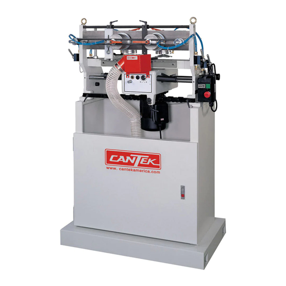
- Page 1 Operations & Parts Manual www.cantekamerica.com JDT65 Manual Dovetailer Please ensure you have your serial number available when contacting us for parts or service. Cantek America Inc. | 1.888.982.2683 | Parts: sales@cantekamerica.com | Service: service@cantekamerica.com...
-
Page 2: Specifications
Tenon and mortise depth are conveniently adjusted according to the thickness of work piece. Equipped with one four-sided template providing four types of pitches between dovetails. SPECIFICATIONS Model JDT-65 JDT-65S Minimum work piece size 200 x 60 mm 1500 x 420 mm... - Page 3 1. Indication Template 2. Open-end Wrench 30mm 3. Hex Wrenches 4. Combination Wrenches (17-19, 12-14, 11-13, 8-10) 5. Fence 6. Fixed Chasers 7. Grease Gun - 2 -...
-
Page 4: Installation And Assembly
Installation & Assembly Tools required for assembly forklift or hoist with straps/slings 14mm wrench (provided) [NOTE: A socket set with ratchet wrench may speed assembly] 1. Remove the four screws and flat washers holding the machine to the pallet with a 14mm Figure 1 wrench, as shown in Figure 1. -
Page 5: Installing Dust Chute
Installing Dust Chute Remove the four socket head cap screws at the rear of the cabinet, using a 4mm hex wrench. Place the 4” diameter dust chute (Figure 5) over the hole, and re-insert and tighten the four socket head cap screws. Dust Collection The use of a dust collection system is strongly recommended for this machine. - Page 6 230 Volt Operation As received from the factory, the JDT-65 THREE-PRONG Dovetailer is designed to run on 230 volt power only. You may either connect a UL/CSA listed 230V plug (similar to the one shown in Figure 6) or “Hard-wire” the machine directly to a control panel.
- Page 7 Adjustments Disconnect machine from power source, shut off air supply and bleed residual air from system, before making adjustments. Failure to comply may cause serious injury. Clamping Cylinders The workpieces are clamped to the table by pneumatically operated aluminum cylinders (A, Figure 8).
- Page 8 The clamping cylinders can also be adjusted laterally for better support of workpieces with differing widths. Simply loosen the locking handle (Figure 10) and slide the clamping cylinder to position. Re-tighten locking handle. Clamping Pressure The pressure exerted by the cylinder clamps against the workpiece can be adjusted at the air regulator, shown in Figure 11.
- Page 9 6. Push the headstock back and re-connect the spring (Figure 12). You must now also shift the indication template (Figure 14). See “Indication Template.” Indication Template Because the tracer pin is not easily observed while the machine is in operation, the indication template (A, Figure 15) provides the operator with a visual record of the progress of the ”hidden”...
- Page 10 1. To replace the fixed chaser, remove the three M6 socket head cap screws and flat washers, using a 5mm hex wrench as shown in Figure 17. Remove the fixed chaser. 2. Install the new fixed chaser and make sure it is level with the main table.
- Page 11 NOTE: Make sure locking handles (A & B, Figure 17) will not interfere with the headstock during operation. 5. Continue to check the spacing by sliding the headstock across, until the dovetail cuts will be distributed evenly across the width of the workpiece.
- Page 12 There are a total of four fences on the 40-050 Dovetailer - two vertical and two horizontal. These allow two sets of workpieces to be cut at the same time. If this is desired, position the other two fences in the same manner as the first two fences, remembering again to offset the vertical fence by half the pitch.
- Page 13 3. To decrease the depth of the mortise (female) cut, turn the bolt clockwise. To increase the depth of the mortise cut, turn the bolt counterclockwise. 4. Re-tighten the hex nut. Thickness of Tenon Cut To adjust the thickness of the tenon (male) cuts, you will change the depth of the tracer pin (A, Figure 20).
- Page 14 NOTE: One notch of the scale equals 1mm. 6. With your fingers on the shank portion of the cutter, carefully rotate the cutter toward the plus (+) or minus (-) position as needed. 7. When satisfied with the adjustment, tighten both set screws firmly.
-
Page 15: Operation
Operation NOTE: The following are basic dovetailing procedures as they apply to this machine, and are not intended to be a full course of instruction in making dovetails. Refer back to the terminology on page 2 if needed. The Dovetailer can be used to make joints in drawers, boxes, cabinets, etc. - Page 16 5. Activate the clamping cylinder in front of the RIGHT SIDE workpiece. 6. Place the drawer BACK on the horizontal table, and against the horizontal fence. Slide it flush against the RIGHT SIDE workpiece. The bottom groove on the BACK should face downward and opposite the fence.
- Page 17 Preventing Chip Out As noted previously, when the SIDE and FRONT/BACK pieces are inserted into the machine, they are offset a bit so they’ll match correctly when assembled. In other words, the SIDE will rest slightly to the right of the FRONT/BACK in the machine. This leaves the right edge of the SIDE exposed without the “chip breaker”...
- Page 18 List of Parts for Dovetailer D65-01A PART NO. REF NO. DESCRIPTION SPECIFICATION D65-1010 WORK TABLE D6501A-01 D6501A-02 D65-1050 BASE GUIDE ROD D6501A-03 HEX. SOCKET SET SCREW M6x16 D6501A-04 SWITCH BRACKET FLAT WASHER M6x16x2 D6501A-05 HEX. SOCKET CAP SCREW M6x16 D6501A-06 SWITCH 1HP.230V D6501A-07...
- Page 19 List of Parts for Dovetailer D65-01A PART NO. REF NO. DESCRIPTION SPECIFICATION D65-1380 BUFFER PAD D6501A-37 D6501A-38 FLAT WASHER M6x13x1 D6501A-39 HEX. SOCKET CAP SCREW M6x20 D6501A-40 POINTER FLAT WASHER D6501A-41 HEX. SOCKET CAP SCREW M5x10 D6501A-42 - 18 -...
- Page 20 List of Parts for Dovetailer D65-02A PART NO. REF NO. DESCRIPTION SPECIFICATION SPINDLE ASS'Y D6502A-01 D6502A-02 D75-2110 BEARING HOUSING D6502A-03 BG6005 BEARING 6005 TB. T63 D6502A-04 D75-2120 BEARING LOCK PIECE D75-2100 SPINDLE D6502A-05 HEX. SOCKET SET SCREW M8x10 D6502A-06 D75-2130 BUSHING D6502A-07 DS1.DS2...
- Page 21 List of Parts for Dovetailer D65-02A PART NO. REF NO. DESCRIPTION SPECIFICATION HEX. SOCKET CAP SCREW M5x35 D6502A-37 D6502A-38 SPRING D6502A-39 HEX. NUT D6502A-40 HEX. SOCKET CAP SCREW M5x20 MOTOR 1Hp. 230V D6502A-41 D65-1170 PULLEY D6502A-42 D75-2310 FLAT WASHER D6502A-43 HEX.
- Page 22 List of Parts for Dovetailer D65-03A PART NO. REF NO. DESCRIPTION SPECIFICATION D6503A-01 CYLINDER ASS'Y D75-4110 CYLINDER BODY D6503A-02 115-4480 PISTON D6503A-03 WEARING 80x75x6 D6503A-04 PISTON BACKING 80x64x5.7 D6503A-05 d75-4120 PISTON ROD D6503A-06 SPRING WASHER D6503A-07 D6503A-08 HEX. NUT D6503A-09 115-4500 END COVER D6503A-10...
- Page 23 List of Parts for Dovetailer DT65-03A PART NO. REF NO. DESCRIPTION SPECIFICATION HEX. SOCKET CAP SCREW M6x16 D6503A-37 - 22 -...
- Page 24 List of Parts for Dovetailer D65-04A PART NO. REF NO. DESCRIPTION SPECIFICATION D65-3010 CABINET D6504A-01 D6504A-02 D65-3020 DOOR D6504A-03 DOOR LOCK D6504A-04 SPRING WASHER HEX. SOCKET CAP SCREW M8x30 D6504A-05 SOCKET SET SCREW M8x20 D6504A-06 HOSE 2-1/2" D6504A-07 DUST HOOD CLAMP 2-3/4"...
- Page 25 - 24 -...
- Page 26 - 25 -...
- Page 27 - 26 -...
- Page 28 - 27 -...
Need help?
Do you have a question about the JDT-65 and is the answer not in the manual?
Questions and answers