Table of Contents
Advertisement
Classic Series 2
Split Ducted Unit
Installation and Commissioning Guide - Indoor
Model Numbers
Single Fan Coil Split Fan Coil**
EVA100S*
EAA130S & EFA130S
EVA130S
EAA150S & EFA150S
EVA150S
EAA170S & EFA170S
EVA170S
EAA200S & EFA200S
EVA200S
EAA230S & EFA230S
EVA230S
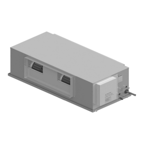
*
Above unit illustration shown is an EVA130S unit.
EVA100S has a single fan configuration.
**
Split fan coil has a separate coil and fan section.
IMPORTANT NOTE:
Please read this manual carefully before installing or operating your air conditioning unit.
Advertisement
Table of Contents

Related Manuals for ActronAir Classic 2 EVA100S Series


Summary of Contents for ActronAir Classic 2 EVA100S Series
- Page 1 Classic Series 2 Split Ducted Unit Installation and Commissioning Guide - Indoor Model Numbers Single Fan Coil Split Fan Coil** EVA100S* EAA130S & EFA130S EVA130S EAA150S & EFA150S EVA150S EAA170S & EFA170S EVA170S EAA200S & EFA200S EVA200S EAA230S & EFA230S EVA230S Above unit illustration shown is an EVA130S unit.
-
Page 2: Table Of Contents
Split Ducted Indoor Units Installation and Commissioning Guide Table of Contents 01. Introduction ...........................3 01.01. Information About This Guide 01.02. Product Inspections 01.03. Codes, Regulations And Standards 01.04. Important Safety Symbols And Labels 02. Safety Instructions .........................4 03. Components Overview ........................5 03.01. -
Page 3: Introduction
Check your air conditioning unit and all items against the invoice upon receiving your shipment. Inspect the unit, components and accessories for any sign of damage. If there is any damage to the unit, contact ActronAir Customer Care Department immediately on: 1300 522 722 to obtain a Goods Return Number. -
Page 4: Safety Instructions
Split Ducted Indoor Units Installation and Commissioning Guide 02. Safety Instructions • Only licensed HVAC technicians* should install and service this air conditioning equipment. Improper service or alteration by an unqualified technician could result in significant and major damage to the product or property which may render your warranty null and void. -
Page 5: Components Overview
Split Ducted Indoor Units Installation and Commissioning Guide 03. Components Overview 03.01. Indoor Unit Components Overview INDOOR UNIT EC MOTOR ID COIL ID FAN Single Fan for EVA100S ELECTRICAL BOX COVER INDOOR CONTROL PANEL 03.02. Indoor Unit Electrical Panel Overview EMC FILTER TRANSFORMER (for some models) -
Page 6: Unit Dimensions And Clearances
ID FAN perimeter is available. 3. Minimum service access clearances are SUPPLY responsibilities of the installer, ActronAir DUCT WORK will not be held liable for any extra HEIGHT CLEARANCE = 340MM charges incurred due to lack of access. -
Page 7: Eva130S
(ELECTRICALS) perimeter is available. ID FAN ID FAN 3. Minimum service access clearances are responsibilities of the installer, ActronAir DUCT WORK will not be held liable for any extra charges incurred due to lack of access. HEIGHT CLEARANCE = 340MM Installation and Commissioning Guide - Split Ducted Indoor Unit Doc. -
Page 8: Eva150S
(ELECTRICALS) ID FAN ID FAN 3. Minimum service access clearances are responsibilities of the installer, ActronAir DUCT WORK will not be held liable for any extra HEIGHT CLEARANCE = 340MM charges incurred due to lack of access. -
Page 9: Eva170S
(ELECTRICALS) ID FAN ID FAN perimeter is available. 3. Minimum service access clearances are responsibilities of the installer, ActronAir DUCT WORK HEIGHT CLEARANCE = 410MM will not be held liable for any extra charges incurred due to lack of access. -
Page 10: Eva200S
(ELECTRICALS) ID FAN ID FAN perimeter is available. 3. Minimum service access clearances are responsibilities of the installer, ActronAir DUCT WORK HEIGHT CLEARANCE = 410MM will not be held liable for any extra charges incurred due to lack of access. -
Page 11: Eva230S
(ELECTRICALS) ID FAN ID FAN 3. Minimum service access clearances are responsibilities of the installer, ActronAir will not be held liable for any extra DUCT WORK HEIGHT CLEARANCE = 340MM charges incurred due to lack of access. -
Page 12: Two-Piece Fan Coil
SERVICE CLEARANCE perimeter is available. CLEARANCE 3. Minimum service access clearances are responsibilities of the installer, ActronAir HEIGHT CLEARANCE = 340MM will not be held liable for any extra DUCT WORK charges incurred due to lack of access. TOP VIEW Installation and Commissioning Guide - Split Ducted Indoor Unit Doc. - Page 13 CLEARANCE CLEARANCE perimeter is available. 3. Minimum service access clearances are responsibilities of the installer, ActronAir HEIGHT CLEARANCE = 340mm will not be held liable for any extra DUCT WORK charges incurred due to lack of access.
- Page 14 CLEARANCE CLEARANCE perimeter is available. 3. Minimum service access clearances are responsibilities of the installer, ActronAir HEIGHT CLEARANCE = 410mm DUCT WORK will not be held liable for any extra TOP VIEW charges incurred due to lack of access.
- Page 15 CLEARANCE or between the unit and the outside CLEARANCE perimeter is available. 3. Minimum service access clearances are responsibilities of the installer, ActronAir HEIGHT CLEARANCE = 410mm DUCT WORK will not be held liable for any extra TOP VIEW charges incurred due to lack of access.
-
Page 16: Fan Section
CLEARANCE CLEARANCE perimeter is available. 3. Minimum service access clearances are responsibilities of the installer, ActronAir DUCT WORK TOP VIEW will not be held liable for any extra FROM COIL SECTION charges incurred due to lack of access. - Page 17 CLEARANCE CLEARANCE perimeter is available. 3. Minimum service access clearances are responsibilities of the installer, ActronAir TOP VIEW DUCT WORK will not be held liable for any extra FROM COIL SECTION charges incurred due to lack of access.
- Page 18 3. Minimum service access clearances are DUCT WORK responsibilities of the installer, ActronAir FROM COIL SECTION will not be held liable for any extra (0M MIN - 6M MAX) charges incurred due to lack of access.
-
Page 19: Installation Instructions
Compliance and consultation with the authorities having jurisdiction with the installation of this equipment is the responsibility of the installer. ActronAir will not be held liable for any damages or costs as a result of the installer’s failure to comply. Please refer to the matching outdoor unit Installation and Commissioning Guide for further information and details. - Page 20 Split Fan Coil System (Optional) The ActronAir innovative 2-piece fan coil system provides a solution to your difficult and tight roof space installation requirement. This versatile system has a separate fan and coil sections. Each of the compact and lightweight section is simply installed in two separate locations and joined by flexible duct system.
-
Page 21: Unit Lifting Procedures
Split Ducted Indoor Units Installation and Commissioning Guide 07. Unit Lifting Procedures 07.01. Crane Lifting Method WARNING WH&S regulations must be observed and will take precedence during lifting process. DANGER Make sure rigging equipment, accessories and plant are sufficiently and safely capable to lift the unit in order to prevent potential damage to property, severe personal injury or death. -
Page 22: Fork Lift Method
Split Ducted Indoor Units Installation and Commissioning Guide 07.02. Fork Lift Method FIG. 2 Insert forklift Tines here ELECTRICAL PANEL END Insert forklift Tines here CAUTION DO NOT LIFT UNIT from this end in order to prevent damage to electrical panel and pipes. Procedure: 1. -
Page 23: Safety Drain Tray
Split Ducted Indoor Units Installation and Commissioning Guide 08. Safety Drain Tray NOTES CONDENSATE AND SAFETY TRAY DRAINAGE • Refer to indoor unit dimension page for specification of drain connectors. • Test condensate drain installation to ensure that water flows freely and does not leak. Also check that the drain tray does REVISION DATE DRAWING NUMBER 05 - 05 - 2010... -
Page 24: Zone Barrel Installation Instructions
(positions that range from 9 o’clock to 3 o’clock), as shown below: It is also recommended that only ActronAir 24V zones be connected to this system using RJ45 cable connections. Warranty may be void if third party zones cause damage to the system. -
Page 25: Electrical Installation
Split Ducted Indoor Units Installation and Commissioning Guide 10. Electrical Installation All electrical work must be carried out by a qualified technician. Make sure all wiring is in accordance with local wiring rules. Wiring connections should be made in accordance with the wiring diagram provided. DANGER Live Electrical Supply ! During installation of your air conditioning unit, it may be necessary to work in close proximity to live electricity. -
Page 26: Wiring Diagram
Split Ducted Indoor Units Installation and Commissioning Guide 11. Wiring Diagram Variation Code: Variation: Base VARIOUS Model No: Description: INDOOR BOARD + 8 ZONE WITH 3 WALL CONTROLLERS Drawn: Date: 08-05-2019 Drawing No: Revision Size: WD2210 This drawing remains the intellectual property of Actron Engineering Pty Ltd. This d 02-06-2020 Date:... -
Page 27: Split Unit Electrical Connection
Split Ducted Indoor Units Installation and Commissioning Guide 12. Split Unit Electrical Connection NOTE To minimise noise interference, Data and Power cable clearance should be maintained as much as possible. DETAILED WIRING DIAGRAM IS PROVIDED WITH THE UNIT. Outdoor Unit: Located at the back of electrical/compressor access panel. Indoor Unit: Located at the back of electrical box cover. - Page 28 Split Ducted Indoor Units Installation and Commissioning Guide 2 Core Twisted Data Cable Shielding Instructions NOTES • Maintain the twist of the core wires up to the Green Terminal Plug. • Maximum strip length of outer insulation to the Green Terminal Plug is 50mm. •...
-
Page 29: Maximum Cable Lengths
Split Ducted Indoor Units Installation and Commissioning Guide Circuit Breaker Size and Cable Size Requirement Circuit Breaker Size Cable Size (mm2) Model Amps MAIN O.D. to I.D. CRA100S / EVA100S 25.0 CRA130S / EVA130S / EFA130S 32.0 CCA130S / EVA130S / EFA130S CRA150S / EVA150S / EFA150S 32.0 CCA150S / EVA150S / EFA150S... -
Page 30: Wiring Configuration : Recommended
Split Ducted Indoor Units Installation and Commissioning Guide 13.02. Wiring Configuration : Recommended LR7-1 INDOOR UNIT WALL CONTROLLER WALL CONTROLLER WALL CONTROLLER (OPTIONAL) (OPTIONAL) (OPTIONAL) LM-RS OUTDOOR UNIT (OPTIONAL) DATA CONTROL AERSS CABLE (OPTIONAL) MEPS MODEL C ERT I FI ED R-410A LIVE ELECTRICAL WITHIN ENCLOSURE ISOLATE ELECTRICAL SUPPLY BEFORE REMOVING PANELS... -
Page 31: Alternate Wiring Configuration
Split Ducted Indoor Units Installation and Commissioning Guide 13.03. Alternate Wiring Configuration INDOOR UNIT LR7-1 WALL CONTROL LR7-1 WALL CONTROL LR7-1 WALL CONTROL (OPTIONAL) (OPTIONAL) (OPTIONAL) OUTDOOR UNIT LM-RS (OPTIONAL) DATA CONTROL CABLE AERSS (OPTIONAL) MEPS MODEL C ERT I FI ED R-410A LIVE ELECTRICAL WITHIN ENCLOSURE ISOLATE ELECTRICAL SUPPLY BEFORE REMOVING PANELS... -
Page 32: Cable Length - Zoning
1 to 4 (Optional 4 Zones Piggy-Back Configuration), if 1 to 3 is 75m, then 3 to 4 must be 25m to make a total of 100m. *** Recommended maximum cable length, providing total of preceding cable connections are only 5m. ^ Total Cumulative length of all the aggregate cable must not exceed 500 meters. Consult ActronAir for longer cable length requirement. -
Page 33: Wiring Connections
Split Ducted Indoor Units Installation and Commissioning Guide 15. Wiring Connections 15.01. LR7-1 and LC7-2 Wall Control Wiring Connections INDOOR CONTROL WALL CONTROL WIRING BOARD WALL CONTROLLER POWER: - BROWN / ORANGE +12V A 485 A: - BLUE 485 B: - BLUE-WHITE GND: - BROWN-WHITE / ORANGE-WHITE... -
Page 34: Lm-Rs-2 Optional Sensor Wiring Connections
Split Ducted Indoor Units Installation and Commissioning Guide 15.03. LM-RS-2 Optional Sensor Wiring Connections REMOTE SENSOR WIRING INDOOR REMOTE SENSOR WIRING PAIR 1 (BLUE / BLUE-WHITE) CONTROL PAIR 2 (ORANGE / ORANGE-WHITE) PAIR 3 (GREEN / GREEN-WHITE) PAIR 1: - BLUE / BLUE-WHITE BOARD PAIR 4 (BROWN / BROWN-WHITE) PAIR 2: - ORANGE / ORANGE-WHITE... -
Page 35: Zone Commissioning
Split Ducted Indoor Units Installation and Commissioning Guide 16. Zone Commissioning When the unit is powered on, a zone detection will automatically occur. This will take 2 minutes to complete. A zone detection can also be manually triggered on the LR7-1/LC7-2 controller by pressing the ON/OFF button and Zone 1 button for 3 seconds. -
Page 36: Maintenance Frequency Checklist
Split Ducted Indoor Units Installation and Commissioning Guide 17. Maintenance Frequency Checklist Regular servicing of equipment by a qualified technician is recommended every 12 months for residential applications and every quarter for commercial applications. Regular servicing of your unit helps in maintaining its optimum performance and reliability. -
Page 37: Key Parts List
Split Ducted Indoor Units Installation and Commissioning Guide 18. Key Parts List PART ITEM DESCRIPTION EVA100S EVA130S EVA150S EVA170S EVA200S EVA230S NUMBER 2520-328 2520-338 EC ID Fan 2520-334 2520-313 4540-067 4540-074 Coil Piston 4540-084 4540-088 4540-099 ID Control Board 2020-169 Filter Board 4080-013 1040-225... - Page 38 THIS PAGE WAS INTENTIONALLY LEFT BLANK...
- Page 39 THIS PAGE WAS INTENTIONALLY LEFT BLANK...
- Page 40 ©Copyright 2019 Actron Engineering Pty Limited ABN 34 002767240. ®Registered Trade Marks of Actron Engineering Pty Limited. ActronAir is constantly seeking ways to improve the design of its products, therefore specifications are subject to change without notice. Document: 0525-074 Ver. 3 Issue Date: 08/2020...
Need help?
Do you have a question about the Classic 2 EVA100S Series and is the answer not in the manual?
Questions and answers