Table of Contents
Advertisement
BMS MODBUS 485
Installation and Commissioning Guide
ICUNO-MOD
IMPORTANT NOTE:
Please read this manual carefully before installing the module in the air conditioning unit.
BMS Modbus is available for compatible units with an
UNO Outdoor Board such as:
Variable
Classic 2
Capacity
Condenser
Commercial
• CRV290T
• CRA100S
• CRV330T
• CRA130S
• PKV160T-T
• CRA130T
• PKV180T-T
• CRA150S
• PKV210T-T
• CRA150T
• PKV240T-T
• CRA170S
• PKV290T-T
• CRA170T
• PKV290T-L/R
• CRA200T
• PKV330T-T
• CRA230T
• PKV330T-L/R
Advance
Condenser
• CRV140S
• CRV160S
• CRV180S
• CRV160T
• CRV180T
• CRV210T
• CRV240T
Advertisement
Table of Contents

Related Manuals for ActronAir BMS MODBUS 485


Summary of Contents for ActronAir BMS MODBUS 485
- Page 1 BMS MODBUS 485 Installation and Commissioning Guide BMS Modbus is available for compatible units with an UNO Outdoor Board such as: Variable Classic 2 Advance Capacity Condenser Condenser Commercial • CRV290T • CRA100S • CRV140S • CRV330T • CRA130S • CRV160S ICUNO-MOD •...
-
Page 2: Table Of Contents
ICUNO-MOD Installation and Commissioning Guide Table of Contents 01. Introduction ............................. 3 01.01. Items to Consider 01.02. Safety Instructions 01.03. Codes, Regulations and Standards 01.04. Waste Electrical and Electronic Equipment Disposal Guidelines 02. Parts Included In ICUNO-MOD......................4 03. ICUNO-MOD ............................ 5 04. -
Page 3: Introduction
• Follow sound Lock Out and Tag Out procedures to ensure that power supply is not re-energised accidentally. ActronAir is constantly seeking ways to improve the design of its products, therefore specifications are subject to change without notice. Copyright © 2019 Actron Engineering Pty. Ltd. -
Page 4: Parts Included In Icuno-Mod
ICUNO-MOD Installation and Commissioning Guide 02. Parts Included In ICUNO-MOD Items Images Quantity ICUNO-MOD Modbus 485 Card DATA Cable (P/N 26117-1) BMS Connectors PCB Mounts Installation and Commissioning Guide ICUNO-MOD Doc. No. 9590-3013 Ver. 5 200722... -
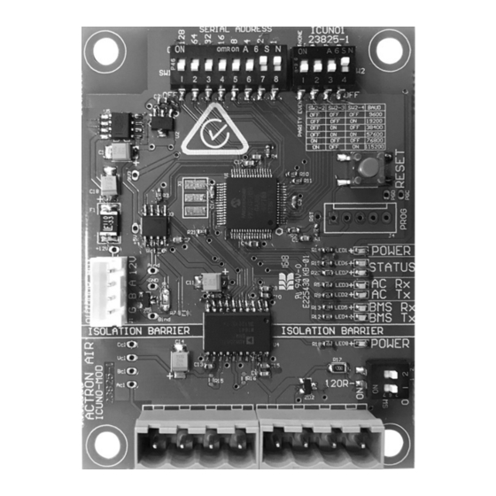
Page 5: Icuno-Mod
PUSH BUTTON STATUS OUTDOOR DATA LEDS CONNECTOR SW3-TERMINATION DIP SWITCH BMS IN/OUT CONNECTORS ActronAir is constantly seeking ways to improve the design of its products, therefore specifications are subject to change without notice. Copyright © 2019 Actron Engineering Pty. Ltd. -
Page 6: Icuno-Mod Installation Procedure
UNO OUTDOOR BOARD AUX 485 DUCT RAIL INTERCONNECTION CABLE: ENSURE TO ROUTE THIS CABLE THROUGH THE DUCT RAIL. ICUNO-MOD OUTDOOR AUX NOTE: The layout will differ between ActronAir systems. Installation and Commissioning Guide ICUNO-MOD Doc. No. 9590-3013 Ver. 5 200722... -
Page 7: Installation For Classic Series 2 (Reverse Cycle - Cra Models)
Single Phase (10kW - 17kW) BMS ICUNO-MOD Three Phase (13kW - 23kW) BMS ICUNO-MOD ActronAir is constantly seeking ways to improve the design of its products, therefore specifications are subject to change without notice. Copyright © 2019 Actron Engineering Pty. Ltd. -
Page 8: Installation For Advance (Crv Models)
Step 3. Test unit with multimeter to ensure there is no power, before starting installation of the BMS card. Step 4. Use supplied PCB Mounts to mount ICUNO-MOD into correct location. NOTE: Location will differ between ActronAir systems. Step 5. Install BMS ICUNO-MOD as shown below. -
Page 9: Bms Installation Procedure
Note: It is required to earth the shield wire of the data cable at the BMS Master end. INTERMEDIATE BMS LAST BMS DEVICE DEVICE TERMINATION TERMINATION DIP SWITCH DIP SWITCH ActronAir is constantly seeking ways to improve the design of its products, therefore specifications are subject to change without notice. Copyright © 2019 Actron Engineering Pty. Ltd. -
Page 10: Bms Configuration Of Icuno-Mod Card
ICUNO-MOD Installation and Commissioning Guide 04.05. BMS Configuration of ICUNO-MOD Card Consult project system designer (BMS engineer or similar role) for the correct Modbus RS-485 configuration for this unit. Use the DIP switches on the BMS Card to configure the Modbus parameters. New BMS configuration will take effect when the BMS card initializes, either by the RESET button or power cycle. -
Page 11: Configure Baud Rate And Data Parity
Status 2 LED (white) will FLASH slowly (once every 2 seconds). See Section 04.07 for BMS Troubleshooting. ActronAir is constantly seeking ways to improve the design of its products, therefore specifications are subject to change without notice. Copyright © 2019 Actron Engineering Pty. Ltd. -
Page 12: Initialisation
Status 2 LED (white) will FLASH (once every 2 seconds). The BMS card will not accept any BMS commands during this time. Step 3. After 60 seconds the Amber Status LED should be ON, indicating a stable connection to the ActronAir Air Conditioning System. -
Page 13: Basic Bms Control
Open and Close zones The ActronAir AC system may be configured to operate in Basic BMS Control, or Basic BMS Control with a Wall Control. When operating in Basic BMS Control with a Wall Control, all settings changes from the BMS and Wall Control will be synchronized across the entire system. -
Page 14: Uno Configuration
ICUNO-MOD Installation and Commissioning Guide A Wall Control can not be used if the ActronAir AC system is configured for Advanced BMS Control. Additional information for controlling the unit in Advanced BMS Control can be found in Section 05.02. 04.07.05. UNO Configuration... - Page 15 • Ensure correct cable specifications throughout BMS RS-485 Network. Redundancy Check has failed) ActronAir is constantly seeking ways to improve the design of its products, therefore specifications are subject to change without notice. Copyright © 2019 Actron Engineering Pty. Ltd.
- Page 16 • See Section 05 for instructions on configuring UNO Outdoor Board for BMS Control. If the above steps fail to fix the problem. Contact ActronAir Technical Support on 1800 119 229 for further assistance. Installation and Commissioning Guide ICUNO-MOD Doc. No. 9590-3013 Ver. 5 200722...
-
Page 17: Basic Bms Control
Installation and Commissioning Guide 05. BMS Control This section of the document provides a guide to using the ActronAir BMS Table. This section explores the Modbus registers relevant to each BMS Operation Mode, their usage and meaning to control the various units. -
Page 18: Basic Bms Points Table
5008 * Fan speed PWM limits can be set from the ActronAir units service menu. Consult the Air Conditioner units installation guide for more information. If system has been configured as a single speed indoor fan Register 4 - Supply fan mode can only be set to MEDIUM speed. -
Page 19: Operating Unit In Advanced Bms Control
* Setting the Indoor Filter timer will reset the Indoor Filter run hours and clear and Air Filter Alarm on the system. ActronAir is constantly seeking ways to improve the design of its products, therefore specifications are subject to change without notice. Copyright © 2019 Actron Engineering Pty. Ltd. -
Page 20: Advanced Bms Points Table
Analog 5008 1. ActronAir software ensures that system operational safety is retained by maintaining minimum and maximum safe compressor demand and fan speed demand. Consult the Air Conditioner unit’s installation guide for safe operating limits. 2. Actual system running capacity (Modbus Analog 801) and Indoor Fan1 Speed (Modbus Analog 1311) will reflect the Set... -
Page 21: Bms Monitoring
Outdoor Unit 1 Software Version Analog 1002 65535 Compressor 1 Type Analog 1004 ActronAir is constantly seeking ways to improve the design of its products, therefore specifications are subject to change without notice. Copyright © 2019 Actron Engineering Pty. Ltd. - Page 22 ICUNO-MOD Installation and Commissioning Guide Description Compressor 1 running status Analog 1101 (0=Off, 1=On) Compressor 1 Heating (0=Off, 1=On) Analog 1102 Compressor 1 Demand (0.1%) Analog 1104 0.1% 0.0% 100.0% Compressor 1 Speed (0.1%) Analog 1105 0.1% 0.0% 100.0% Compressor 1 Unit Defrosting Analog 1107 (0 = Off, 1 = Defrosting)
-
Page 23: Modbus Rs-485 Technical Data
Maximum Network Cable Length 1000 meters (@9600 baud rate) Standard Modbus over serial line v1.0 ActronAir is constantly seeking ways to improve the design of its products, therefore specifications are subject to change without notice. Copyright © 2019 Actron Engineering Pty. Ltd. - Page 24 Refrigerant Trading Authorisation No.: AU06394 ©Copyright 2019 Actron Engineering Pty Limited ABN 34 002767240. ®Registered Trade Marks of Actron Engineering Pty Limited. Document No. 9590-3013 Ver. 5 Issue Date: 07/2020...
Need help?
Do you have a question about the BMS MODBUS 485 and is the answer not in the manual?
Questions and answers