Table of Contents
Advertisement
Advertisement
Table of Contents

Related Manuals for ActronAir PKV160T


Summary of Contents for ActronAir PKV160T
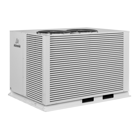
- Page 1 Variable Capacity Commercial Package Ducted Units Installation and Commissioning Guide Model Numbers Under/Over Configuration PKV160T PKV180T PKV210T PKV240T IMPORTANT NOTE: Please read this manual carefully before installing or operating your air conditioning unit.
-
Page 2: Table Of Contents
05. Wall Control Operation Instruction Access .................. 7 06. Components Overview ....................... 7 07. Package Unit Dimensions and Clearances ..................9 07.01. Package Models: PKV160T / PKV180T 07.02. Package Models : PKV210T / PKV240T 08. Unit Lifting Procedure ....................... 13 09. -
Page 3: Inspections
Check your air conditioning unit and all items against the invoice upon receiving your shipment. Inspect the unit, components and accessories for any sign of damage. If there is any damage to the unit, contact ActronAir Customer Care Department immediately on: 1300 522 722 to obtain a Goods Return Number. -
Page 4: Safety Instructions
External fasteners in all Outdoor and Package unit are stainless steel screws Gem-Cote coating. System Flexibility The ActronAir Variable Capacity range air conditioning units is the first choice for commercial applications, both for new construction or retrofitting projects. Refrigerant Handling and Accountability ActronAir strongly urges that all service technicians make every effort possible to reduce the emission of refrigerants to the atmosphere. -
Page 5: Installation Information
Variable Capacity Commercial Installation and Commissioning Guide • Installer must incorporate a means of electrical disconnection (isolator) in the sub mains fixed wiring in accordance with the latest edition of the AS/NZS 3000 (also known as Australian Wiring Rules). • Secure the power cords and control cables that goes in/out the unit. Use the cable ties provided in the control box. *Qualifications required will be appropriate Electrical, Refrigeration and Refrigerant Handling License and Training dependent on local State/Territory regulations. - Page 6 Variable Capacity Commercial Installation and Commissioning Guide Do not open the system to the atmosphere for service work until refrigerant is fully removed and/or recovered. Perform refrigeration system evacuation, prior to charging, in accordance with AIRAH / IRHACE Refrigerant handling code of practice.
-
Page 7: Wall Control Operation Instruction Access
Installation and Commissioning Guide 05. Wall Control Operation Instruction Access Download from website LC7-2 Operation Instruction can be downloaded through our website shown below. https://www.actronair.com.au/brochures-manuals/#operating-manuals Operation Instructions can be accessed through our website shown below. http://neo.actronair.com.au/user-guide/ Updated Drawing 06. Components Overview... - Page 8 Variable Capacity Commercial Installation and Commissioning Guide Outdoor Unit Electrical Panel Overview PKV160T/PKV180T INDOOR FAN CONTROL CIRCUIT CIRCUIT BREAKER BREAKER CONDENSER FERRITES FAN TERMINAL VSD CIRCUIT CMI POWER BLOCKS BREAKER SUPPLY BOARD UNIT MAINS INPUT TERMINAL BLOCKS CONDENSER FAN RUN...
-
Page 9: Package Unit Dimensions And Clearances
3. Minimum service access areas and spaces for airflow COMP 1250 O/A clearances are responsibilities of the installer, ActronAir will not be held liable for any extra charges incurred due to lack of access and space for airflow. 4. Under all circumstances, condenser air must not recirculate back onto condenser coil. - Page 10 • Keep all clearances free of any obstructions. Base Mounting Details 1220 1488 Corner Weights (Kg) Center of Gravity Unit Model Unit Weight Number (Kg) PKV160T PKV180T Installation and Commissioning Guide - Package Ducted Variable Capacity Commercial Doc. Part No. 0525-076 Ver. 3 210414...
-
Page 11: Package Models : Pkv210T / Pkv240T
3. Minimum service access areas and spaces for airflow clearances are responsibilities of the installer, ActronAir will COMP not be held liable for any extra charges incurred due to lack of access and space for airflow. - Page 12 Variable Capacity Commercial Installation and Commissioning Guide Minimum Service Access Clearances and Airflow Space Allowances DUCT WORK ID COIL INDOOR INDOOR MOTOR FANS FANS 300 mm 800 mm Service Service Clearance Clearance and Airflow (Compressor Allowance Electrical Control) OUTDOOR COIL HEIGHT CLEARANCE = 1500mm 600 mm Service Clearance and...
-
Page 13: Unit Lifting Procedure
Variable Capacity Commercial Installation and Commissioning Guide 08. Unit Lifting Procedure WARNING WH&S regulations must be observed and will take precedence during lifting process. Crane Lifting Method Crane lifting method is recommended for high rise lifting. Provide rubber pads to prevent damage Connect the loop ends to the unit of slings into shackle... - Page 14 Variable Capacity Commercial Installation and Commissioning Guide PROCEDURE: 1. Remove all screws and washers that secure the unit to the timber pallet. 2. Use 4 x Bow or Dee shackle to connect the lifting holes. 3. Slip nylon slings through all shackles. 4.
-
Page 15: Package Unit Preparation
Variable Capacity Commercial Installation and Commissioning Guide 09. Package Unit Preparation NOTE It is important to remove the shipping blocks before unit operation. Step 1. Remove Access Panel, as shown below: PACKAGE UNIT Access Panel Use allen keys to remove the Access Panel (Hex Recess 8mm) Do not disconnect Earth Cable. - Page 16 Variable Capacity Commercial Installation and Commissioning Guide Step 2. Remove Shipping Blocks. Loosen the set bolts that hold the compressor down onto the unit (3 pcs) PKV210T / PKV240T PKV160T / PKV180T PKV160T-180T New Drawing PKV210T-240T New Drawing Loosen Bolts...
- Page 17 Variable Capacity Commercial Installation and Commissioning Guide Step 3. Tighten back the set bolts that hold the compressor down onto the unit (3pcs). PKV160T / PKV180T PKV210T / PKV240T Tighten Bolts Tighten Bolts (3-pcs / Comp.) (3-pcs / Comp.) Installation and Commissioning Guide- Package Ducted Variable Capacity Commercial...
-
Page 18: Condensate And Safety Tray Drainage Instructions
Variable Capacity Commercial Installation and Commissioning Guide PKV210-240T-T 10. Condensate and Safety Tray Drainage Instructions OUTDOOR COIL Seal with Silicon Sealant Ensure Drain Connection Drain Pipe slopes down from the unit at MOTOR INDOOR INDOOR a minimum of 10mm per metre. FANS FANS TOP VIEW... -
Page 19: Electrical Installation
Variable Capacity Commercial Installation and Commissioning Guide 11. Electrical Installation All electrical work must be carried out by a qualified technician. Make sure all wiring is in accordance with local wiring rules. Wiring connections should be made in accordance with the wiring diagram provided. DANGER Live Electrical Supply ! •... -
Page 20: Package Unit Electrical Connection
SUB-MAIN TO UNIT CIRCUIT BREAKER SIZE AND CABLE SIZE REQUIREMENT Circuit Breaker Size Cable Size * (mm Model Amps Main PKV160T 20.0 PKV180T 20.0 PKV210T 25.0 PKV240T 25.0 * Suggested Minimum Cable Size should be used as a guide only. Larger size cables may be required dependent on installation method, length of cables and ambient temperature. -
Page 21: Maximum Cable Length
Variable Capacity Commercial Installation and Commissioning Guide 13. Maximum Cable Length 13.01. Wall Controller Options Maximum of three (3) wall controllers in below combinations is allowed on unit. See below table. Wall Controllers Combinations WC 1 WC 2 WC 3 1st Option 2nd Option 3rd Option... -
Page 22: Wiring Configuration 1 : Recommended
Variable Capacity Commercial Installation and Commissioning Guide 13.02. Wiring Configuration 1 : Recommended LC7-2 WALL CONTROLLER 3 WALL CONTROLLER 1 WALL CONTROLLER 2 (OPTIONAL) (OPTIONAL) (OPTIONAL) LM-RS-2 (OPTIONAL) AERSS (OPTIONAL) NOTES • Diagram shown above is a general representation only. Refer to individual unit wiring diagram for complete wiring connection details. -
Page 23: Wiring Configuration 2 : Alternate
Variable Capacity Commercial Installation and Commissioning Guide 13.03. Wiring Configuration 2 : Alternate LC7-2 LC7-2 LC7-2 WALL CONTROL 1 WALL CONTROL 2 WALL CONTROL 3 (OPTIONAL) (OPTIONAL) (OPTIONAL) LM-RS-2 (OPTIONAL) AERSS (OPTIONAL) NOTES • Diagram shown above is a general representation only. Refer to individual unit wiring diagram for complete wiring connection details. -
Page 24: Wiring Connections
Variable Capacity Commercial Installation and Commissioning Guide 14. Wiring Connections 14.01. LC7-2 Wall Control Wiring Connections INDOOR CONTROL BOARD WALL CONTROL WIRING WALL CONTROLLER POWER: - BROWN / ORANGE +12V A 485 A: - BLUE 485 B: - BLUE-WHITE GND: - BROWN-WHITE / ORANGE-WHITE NOT USED: - GREEN / GREEN-WHITE WALL CONTROL... -
Page 25: Lm-Rs-2 Optional Sensor Wiring Connections
Variable Capacity Commercial Installation and Commissioning Guide 14.03. LM-RS-2 Optional Sensor Wiring Connections OPTIONAL OPTIONAL SENSOR 2 SENSOR 1 LM-RS-2 LM-RS-2 REMOTE SENSOR WIRING REMOTE SENSOR WIRING PAIR 1: - BLUE / BLUE-WHITE PAIR 1 (BLUE / BLUE-WHITE) PAIR 2 : - ORANGE /ORANGE-WHITE PAIR 2 (ORANGE / ORANGE-WHITE) NOT USED: - PAIR 3 (GREEN /GREEN-WHITE) -
Page 26: Configuring And Commissioning Setup
Third Party Control The unit can be controlled by a non-ActronAir Wall Control. To do this, CtrS on the Outdoor Board has to be set to Ct. 0. For connection details, see the wiring diagram supplied with the outdoor unit. -
Page 27: Configuring Indoor Fan Setting (Idus)
Wall Control ActronAir offers NEO and LC7-2, wall controls that can control the available features and maximise the function and operation of the air conditioner. To do this, CtrS on the Outdoor Board has to be set to Ct. 1. - Page 28 Variable Capacity Commercial Installation and Commissioning Guide Option 1: Via LC7-2 Wall Control Summary : Enter Service Menu Select 1-Speed or If required, adjust the PWM Select Menu 03 3-Speed Indoor Fan of 1-Speed Setting If required, adjust the MED If required, adjust the LOW If required, adjust the LOW PWM of 3-Speed Setting...
- Page 29 Example here is 110 x 10 = 1100 RPM. • ActronAir do not recommend adjusting the RPM limit. • Before making any changes, please contact ActronAir Technical Support on 1800 119 229. 8. Repeat Steps 6-7 to set MED and then HIGH PWM and RPM limit settings.
- Page 30 Option 2: via Outdoor Board The outdoor PCB has a 7 segment display, with 3 adjacent buttons, used for commissioning the indoor fan. PWM / RPM SPEED SETTING MENU iduS PKV160T PKV180T PKV210T PKV240T 3 - SPEED 1 - SPEED Low PWM Med PWM...
- Page 31 Variable Capacity Commercial Installation and Commissioning Guide 4. On the CMI Board, ensure that all dip switches are set as per below image. 5. Indoor Fan operation is now operational via Third Party Control (1-speed). 15.04.02. Defrost Fan Setting This feature allows the installer to set the indoor fan speed (PWM) during defrost mode. By default, this is set to 0 PWM (Fan Off) to avoid cold air draft.
- Page 32 Variable Capacity Commercial Installation and Commissioning Guide 15.04.03. Reduced Airflow This feature allows the system to run at lower airflow down to 20% (below system normal application range) when the compressor is not active (cycle off). This feature is useful to reduce the indoor fan power consumption during system operation but maintain the essential air circulation in the room.
- Page 33 Variable Capacity Commercial Installation and Commissioning Guide 3. Press the PROG button 11x times to enter the Hot Start Settings. 4. Press the buttons to enable/disable the hot start operation. 5. Press the PROG button to accept the Hot Start setting. 6.
- Page 34 Variable Capacity Commercial Installation and Commissioning Guide 4. Press the buttons to enable economy damper, then press PROG to accept. 5. Press the PROG button enter economy damper setting. 6. Press the buttons to adjust the voltage output in 0.1V increments (0 to 10V) , then press PROG to accept.
-
Page 35: Optional Output/Input Relay
Variable Capacity Commercial Installation and Commissioning Guide 4. Press the buttons to select OFF. Then press the PROG button to accept. 5. Press the BACK button twice to go back to the original status display. 15.04.08. Run and Fault Indication Output Run Output is configurable to indicate that the unit is running. -
Page 36: Fan Run Indication Output (Cmi Board)
Variable Capacity Commercial Installation and Commissioning Guide 16.02. Fan Run Indication Output (CMI Board) Allows for optional Fan Run Indication (12VDC) INDOOR COIL TEMP SENSOR OPTIONAL COIL +12V FAN RUN SENSOR TEMP OUTPUT +12V INDICATION OUTPUT 0-10V 0-10V 16.03. Optional Outside Air Damper Control Output (CMI Board) 0-10V This feature allows to set the optional outside air damper opening (0-10V). - Page 37 Variable Capacity Commercial Installation and Commissioning Guide Input (DC) Output Fan Status 0.0V to 0.99 V 1.0V to 1.49 V 0 or 20% Off or On 1.5V to 9.5 V 20% to 100% 9.5V to 10 V 100% +12V STANDARD DIP SWITCH SETTINGS 0-10V 1 2 3 4 5 6 7 8...
- Page 38 +12V 1 2 3 4 5 6 7 8 0-10V Variable Capacity Commercial Installation and Commissioning Guide OUTPUT 0-10V 0-10V THIRD PARTY INPUT 0-10V COMPRESSOR 0-10VDC CONTROL INPUT INPUT 0-10V +12V +12VDC DRM3 COMP INDOOR FAN DRM2 REMOTE ON/OFF DRM1 HEAT G 12V HEAT...
-
Page 39: Demand Response Management (Outdoor Board)
Variable Capacity Commercial Installation and Commissioning Guide 16.05. Demand Response Management (Outdoor Board) These products are compliant to AS/NZS 4755.3.1:2012 NOTE Third Party Control Option is not available if Demand Response Management (DRM) is used. CONDENSER BOARD COM / +12VDC DRM 3 / COMP DRM 2 / FAN DRM 1 / HEAT... -
Page 40: Run And Fault Indication Output (Outdoor Board)
Variable Capacity Commercial Installation and Commissioning Guide 16.06. Run and Fault Indication Output (Outdoor Board) To activate, the unit must be wired as illustrated below. See Section 15.04.08 for configuration. If required, a fault output connection terminal is also available to show any error/fault with the a/c system. RUN/FAULT relay outputs (230VAC/5A MAX) connection CONDENSER OUTPUT... -
Page 41: Indoor Fan Table And Fan Curve
Variable Capacity Commercial Installation and Commissioning Guide 17. Indoor Fan Table And Fan Curve 17.01. PKV160T APPLICATION RANGE (COMPRESSOR ON) EXTERNAL STATIC PRESSURE (Pa) AIRFLOW % PWM % PWM % PWM % PWM % PWM % PWM (l/s) MOTOR / BLOWER LIMIT... - Page 42 Variable Capacity Commercial Installation and Commissioning Guide Installation and Commissioning Guide - Package Ducted Variable Capacity Commercial Doc. Part No. 0525-076 Ver. 3 210414...
-
Page 43: Pkv180T
Variable Capacity Commercial Installation and Commissioning Guide 17.02. PKV180T APPLICATION RANGE (COMPRESSOR ON) EXTERNAL STATIC PRESSURE (Pa) AIRFLOW % PWM % PWM % PWM % PWM % PWM % PWM (l/s) MOTOR / BLOWER LIMIT 1000 1020 REDUCED AIRFLOW *(COMPRESSOR OFF) EXTERNAL STATIC PRESSURE (Pa) AIRFLOW % PWM... - Page 44 Variable Capacity Commercial Installation and Commissioning Guide Installation and Commissioning Guide - Package Ducted Variable Capacity Commercial Doc. Part No. 0525-076 Ver. 3 210414...
-
Page 45: Pkv210T
Variable Capacity Commercial Installation and Commissioning Guide 17.03. PKV210T APPLICATION RANGE (COMPRESSOR ON) EXTERNAL STATIC PRESSURE (Pa) AIRFLOW % PWM % PWM % PWM % PWM % PWM % PWM (l/s) 1000 1050 1100 1150 MOTOR / BLOWER LIMIT 1200 REDUCED AIRFLOW *(COMPRESSOR OFF) EXTERNAL STATIC PRESSURE (Pa) AIRFLOW... - Page 46 Variable Capacity Commercial Installation and Commissioning Guide Installation and Commissioning Guide - Package Ducted Variable Capacity Commercial Doc. Part No. 0525-076 Ver. 3 210414...
-
Page 47: Pkv240T
Variable Capacity Commercial Installation and Commissioning Guide 17.04. PKV240T APPLICATION RANGE (COMPRESSOR ON) EXTERNAL STATIC PRESSURE (Pa) AIRFLOW % PWM % PWM % PWM % PWM % PWM % PWM (l/s) 1000 1050 1100 1150 1200 1250 MOTOR / BLOWER LIMIT 1300 1320 845.5... - Page 48 Variable Capacity Commercial Installation and Commissioning Guide Installation and Commissioning Guide - Package Ducted Variable Capacity Commercial Doc. Part No. 0525-076 Ver. 3 210414...
-
Page 49: Refrigerant Charging
The system of this unit operates with POE oil that rapidly absorbs moisture. The maximum time any system can be opened to atmosphere is 15 minutes. REFRIGERANT CHARGE DETAILS (R-410A) Model Refrigerant Charge (g) PKV160T 5,600 PKV180T 6,680 PKV210T 6,800... - Page 50 It is necessary to add refrigerant charge or check EEV settings. Allow the systems to stabilise (15-30 mins) and repeat the step 1-3 until superheat falls within the range specified in the table below: COOLING HEATING Models Subcooling Superheat Subcooling Superheat PKV160T 7 �1 3 �1 12 �1 2 �1 PKV180T 8 �1 4 �1 13 �1 6 �1...
- Page 51 Variable Capacity Commercial Installation and Commissioning Guide R-410A PRESSURE / TEMPERATURE CHART Temp Pressure Temp Pressure Temp Pressure Temp Pressure °C °C °C °C -34.4 194.9 805.9 2090.7 -30.7 206.9 834.1 2145.5 -26.8 219.2 862.9 2201.3 -22.8 231.9 892.6 2258.2 -18.6 245.1 922.8...
-
Page 52: Maintenance Procedures
Variable Capacity Commercial Installation and Commissioning Guide 19. Maintenance Procedures This section describes the procedure that must be performed as a part of normal maintenance PROG. Regular servicing of equipment by licensed technician is highly recommended. Regular servicing of your unit helps in maintaining its optimum performance and reliability. - Page 53 Variable Capacity Commercial Installation and Commissioning Guide CAUTION Do Not Use High Alkaline Detergent ! When using detergent for coil cleaning, ensure that the alkaline level is no higher than 8.5, which can cause corrosion damage to the coils. No Water into the Drive! Ensure consideration is given to the possibility of water entering the electrical compartments during cleaning of the condenser coil.
-
Page 54: Maintenance Frequency Checklist
Variable Capacity Commercial Installation and Commissioning Guide 20. Maintenance Frequency Checklist ELECTRICAL Service Period Parts Detail of Service Check Service Methods Mths Mths Printed Circuit Tighten Terminals as necessary Visual Inspection Boards on printed circuit boards Electrical Check all electrical terminals, ... - Page 55 Variable Capacity Commercial Installation and Commissioning Guide OUTDOOR SECTION Service Period Parts Detail of Service Check Service Methods Mths Mths For highly corrosive environment, wash panels Casing / Panels Visual check for damage, rust quarterly with water and neutral and dust accumulation.
-
Page 56: Start Up And Commissioning Report
Variable Capacity Commercial Installation and Commissioning Guide 21. Start Up and Commissioning Report INSTALLATION INFORMATION Name: Tel. Number: CUSTOMER Address: Name: Tel. Number: INSTALLER Address: Site Address: Date Installed: Model: Serial Number: CIRCUIT TEMPERATURE SETTINGS AND AMBIENT TEMPERATURE SYSTEM 1 SYSTEM 2 Supply Air Temperature °C... - Page 57 THIS PAGE WAS INTENTIONALLY LEFT BLANK...
- Page 58 THIS PAGE WAS INTENTIONALLY LEFT BLANK...
- Page 59 THIS PAGE WAS INTENTIONALLY LEFT BLANK...
- Page 60 ©Copyright 2019 Actron Engineering Pty Limited ABN 34 002767240. ®Registered Trade Marks of Actron Engineering Pty Limited. ActronAir is constantly seeking ways to improve the design of its products, therefore specifications are subject to change without notice. Document: 0525-076 Ver. 3 Issue Date: 04/2021...
Need help?
Do you have a question about the PKV160T and is the answer not in the manual?
Questions and answers