Table of Contents
Advertisement
Quick Links
Advertisement
Table of Contents

Related Manuals for WHALETEQ DFS100


Summary of Contents for WHALETEQ DFS100
- Page 1 WHALETEQ DFS100 User Manual Revision 2021-08-03...
- Page 2 This document could contain technical inaccuracies or typographical errors. Changes are periodically made to the information herein; these changes will be incorporated in future revisions of this document. WhaleTeq Co. LTD. is under no obligation to notify any person of the changes.
-
Page 3: Table Of Contents
Contents Introduction ..................6 1.1 Concept .................... 6 1.2 Applications ..................6 Specification ..................7 2.1 General Specifications ..............7 2.2 Energy Measurement Specifications ..........7 2.3 ECG Signal Specifications..............8 Instrument Familiarization ..............9 3.1 Top ....................9 3.2 Front and Rear ................11 3.3 Back .................... - Page 4 12 Revision History ................22 13 Contact WhaleTeq ................22...
- Page 5 Table 6: DFS Battery LED ..............10 Table 7: DFS100 Test System ............21 Table 8: Optional Accessories ............21 Table 9: Optional Calibration Service and Warranty Extension ..21 Table 10: DFS100 Standard Package Content ......... 22 Table 11: User Manual Revision History .......... 22...
- Page 6 List of Figures Figure 1: Top Side of DFS100 ............. 9 Figure 2: Front and Rear Side of DFS100 ......... 11 Figure 3: Back Side of DFS100 ............12 Figure 4: Wiring Diagram ..............13 Figure 5: PC Operation Interface ............. 17...
-
Page 7: Introduction
DFS100 is the ideal tool to conduct such a regular inspection. Applications WhaleTeq DFS100 is a compact field tester, functioning as an ECG signal simulator and defibrillation energy guarantee equipment for AED regular maintenance. -
Page 8: Specification
Specification General Specifications Table 1: General Specifications Function Spec (DFS100) Operating: 0 °C to 50 °C (+32 °F to +122 °F) Temperature Storage: -20 °C to +60 °C (-4 °F to +140 °F) Humidity 10 % to 90 % non-condensing... -
Page 9: Ecg Signal Specifications
Function Spec (DFS100) Range: 1.0 to 50.0 ms Pulse Width ±0.1 ms Accuracy: Range: Up to 5000 V ± (1 % of reading + 2 V) Accuracy: Voltage Note: 5000V is the V Sample rate 100 kHz (10 μs sample) Maximum 12 W, equivalent to 1 defib. -
Page 10: Instrument Familiarization
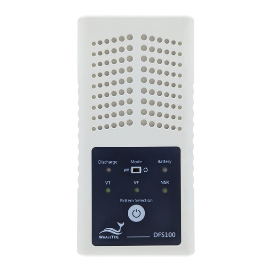
Instrument Familiarization Figure 1: Top Side of DFS100 Ventilation Holes: Allow ventilation during operation. Keep this side up when in use. AED Discharge LED: Table 4: AED Discharge LED Scenario LED behavior No Discharge No light If the discharge value equals to or is greater Discharge than the joule number set in 5.1 (C), the green... -
Page 11: Table 5: On/Off And Pattern Selection Button
Table 5: On/Off and Pattern Selection Button Scenario Button behavior Press the button for about 1 second to turn on DFS100. When DFS Battery LED (F) indicates DFS100 is Pattern on, the button function becomes pattern Selection selection. Long press the button for 3 seconds to turn off DFS100. -
Page 12: Front And Rear
AED pad labeled Sternum via DFS accessory “AED Interface Cable”. Caution: DFS100 is recommended to be used for analyzing defibrillation shock at the interval of at least 60 seconds apart. Caution, the possibility of electric shock: From the time AED starts charging for defibrillation until right after energy delivery, User is recommended to stay clear from DFS100. -
Page 13: Back
Back Figure 3: Back Side of DFS100 Label: Contain information including model, serial number, manufacturer, and power supply. M. Battery Compartment: Insert a 9V battery for power supply. Both disposable batteries and rechargeable batteries can be used. -
Page 14: Wiring Diagram
Wiring Diagram Figure 4: Wiring Diagram Note: To plug in properly, please make sure the yellow lines on the black and red banana males that connect to DFS100 totally disappear in the jacks. -
Page 15: Getting Started
Getting Started PC System Requirements DFS100 Setup Software uses a Windows PC to connect and modify DFS100 via USB module. PC requirements: - Windows PC (Windows 7 or later, suggest to use the genuine version) - Microsoft .NET 4.0 or higher - Administrator access (essential for installing software, driver, and Microsoft .Net Framework) -
Page 16: Usb Driver Installation
Device Manager to recognize and install the driver. For Microsoft Windows 8 and Windows 8.1 ⚫ If Windows 8 and Windows 8.1 can’t recognize DFS100 unit, please download “mchpcdc.inf” from WhaleTeq’s website. This driver is provided by Microchip®, and is intended to be used with PIC microprocessors which have built-in USB functions. -
Page 17: Microsoft .Net Framework Installation
Microsoft’s website. Please click here to watch the tutorial video (from 2:03). PC Software and Firmware Auto-Update User can download the latest software from WhaleTeq’s website. If User cannot update the DFS software, please contact WhaleTeq’s service team (service@whaleteq.com). -
Page 18: Pc Software Operation
PC Software Operation Software Function Introduction Figure 5: PC Operation Interface The DFS100 PC Software is solely for customized settings. It does not include testing functions. A. Default Pattern When On: User can choose from VT (Ventricular Tachycardia), VF (Ventricular Fibrillation), or NSR (Normal Sinus Rhythm) as the default playing pattern when turning on DFS100. - Page 19 Note: User can set the time from 3 to 10 minutes. E. Check for Updates: Click to see if the latest version of firmware and/or software has been released. Please note that the USB cable used for firmware upgrade must be file-transferrable. F.
-
Page 20: Standalone Operation
Note: If the test passes, the LED lights green. If the test fails, the LED lights red. Then, User may connect DFS100 to the other AED for the next test. The test starts without User pressing any button on DFS100. -
Page 21: Calibration And Validation
(2) Follow the color code and / or labeling when connecting DFS100 and the AED via the AED interface cable. (3) When DFS100 is in use, the face containing LEDs and buttons must face up to allow ventilation. (4) To allow ventilation, DFS100 should be used to analyze defibrillation energy at the interval of at least 60 seconds. -
Page 22: Ordering Information
(10) When not in use for a longer period, remove the battery from DFS100 to ensure a longer lifespan of the battery. (11) Clean the external case of the DFS100 with a clean dry cloth. Do not allow liquid inside DFS100 or near the I/O sockets. -
Page 23: Package Contents
Package Contents Table 10: DFS100 Standard Package Content Item Q'ty DFS100 AED field tester main device 9V alkaline battery Open-ended AED cable (Banana Male), 0.5 meter (Black) Open-ended AED cable (Banana Male), 0.5 meter (Red) Compact splicing connector DFS100 Optional Accessories ✓...
Need help?
Do you have a question about the DFS100 and is the answer not in the manual?
Questions and answers