
Related Manuals for WHALETEQ CMRR 3.0


Summary of Contents for WHALETEQ CMRR 3.0
- Page 1 Common Mode Rejection Ratio Tester | User manual WHALETEQ Common Mode Rejection Ratio Tester (CMRR 3.0) User Manual (Revision 2017-10-06)
- Page 2 WhaleTeq Co. LTD. Disclaimer WhaleTeq Co. LTD. provides this document and the programs "as is" without warranty of any kind, either expressed or implied, including, but not limited to, the implied warranties of merchantability or fitness for a particular purpose.
-
Page 3: Table Of Contents
RA/LA/LL/RL/V1~V6 Electrode Terminals Operation Unit Operation 6.1.1 Choose [Setting] and [Select] Knob to Set Various Parameters 6.1.2 Test Exemplification Software Operation 6.2.1 CMRR 3.0 PC Software 6.2.2 CMRR 3.0 Assistant Software Caution Baseline noise test Battery power consumption for DC offset function... - Page 4 Common Mode Rejection Ratio Tester | User manual Vs voltage drop with the multimeter of 1MΩ input impedance CMRR3.0 Specifications Ordering Information Package Contents Optional Accessories 10 Contact Information...
-
Page 5: Introduction
However, those systems do not cover common mode rejection ratio due to the nature of test (double box construction, noise free environment). To meet this need, WhaleTeq had developed CMRR 2.0 test system and CMRR 2.0 requires an external function generator and multimeter to set up the test environment. Considering the additional equipment CMRR 2.0 requires, this would cause test to become complicated. -
Page 6: Electrical Diagram
2 Electrical Diagram Figure 2-1 indicates the electrical diagram of CMRR 3.0. Ct is the adjustable variable capacitance and Cx is the stray capacitance between inner shield and outer shield. Figure 2-1, CMRR3.0 Electrical Diagram... -
Page 7: Set Up A Noise Free Test Environment
Once set up the test environment per figure 3-1, turn on ECG DUT and adjust the sensitivity level to 10 mm/mV. After that, turn off line frequency notch filter of ECG DUT and adjust Supply Voltage of CMRR 3.0 to “off”. Make sure ECG noise level is below 1mm (0.1 mVpp). -
Page 8: Shielding Case Assembling Instructions For Testing Holter Monitor
(3) Wrapped patient cables and ECG DUT with the foil paper. Connect the foil paper portion of patient cables to CM Point of CMRR 3.0 and connect the foil paper portion of ECG DUT to the reference outer shielding which refer to any screw holes of the shielding case. -
Page 9: Common Mode Rejection In Ecg Equipment
Common Mode Rejection Ratio Tester | User manual mode voltage will come through as an error. The common mode rejection ratio or CMRR indicates the ability of the equipment to reject these common mode voltages. A scale of dB is normally used as the ratio can range from as low as 100 up to 100,000 (40dB to 100dB). A CMRR of 60dB indicates a ratio of 1000, and means that common mode voltages will be reduce by a factor of 1000. -
Page 10: Panel Function
HV probe is removed, which should be accounted for if such probes are used. WhaleTeq CMRR3.0 equipment resolved the difficulty in measuring Vc by using 100MΩ/10MΩ 11:1 voltage divider and voltage measuring circuit to measure the common mode voltage Vc after 100pF automatically. -
Page 11: Lcd Display
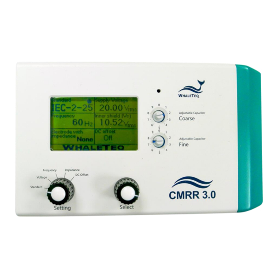
Common Mode Rejection Ratio Tester | User manual Figure 5-1, the upper panel of CMRR3.0 The whole CMRR3.0 operation can be done with the knobs on the upper panel. All of the parameters can be shown on the LCD display of the panel. 5.1.1 LCD Display It displays all the set parameters. -
Page 12: Front Panel
Common Mode Rejection Ratio Tester | User manual user can press the hidden switch again or directly turn off the power switch, to stop the high voltage output. Under the manual mode, the [70.71 Vrms] option can be selected to test a higher CMRR value. Front Panel The front panel of CMRR3.0 is shown in figure 5-2. -
Page 13: Vs] Terminal
Common Mode Rejection Ratio Tester | User manual 5.2.6 [Vs] Terminal The voltage output of CMRR3.0 built-in sine wave signal generator. This is intended for use in equipment calibration. 5.2.7 [Monitor] Terminal The output terminal of inner common mode point after it passes through 11:1 voltage divider. It measures the voltage of Vc decayed by a factor of 11 directly. -
Page 14: Operation
Common Mode Rejection Ratio Tester | User manual Operation Unit Operation Before operating CMRR3.0, the bundled DC 12V power supply has to be connected to the [DC 12V] connector on the front panel with the switch at the right side to be turned to [On]. All of the features of CMRR3.0 unit operation can be done with knobs on the upper panel. - Page 15 Common Mode Rejection Ratio Tester | User manual Figure 6-2, Options in [Supply Voltage] and [Frequency] 6.1.1.3 Inner Shield Vc Once [Supply Voltage] (Vs) is chosen, the [Coarse] / [Fine] knobs can be tuned to Inner shield Vc =Vs/2. This action automatically measures and monitors the voltage that passes variable capacitance Ct with built-in Vc voltage test circuit.
-
Page 16: Test Exemplification
6.1.2 Test Exemplification 6.1.2.1 IEC60601-2-25: 2011 IEC 60601-2-25 is the testing standard for 12 leads diagnostic ECG. User can use CMRR 3.0 and follow the below testing procedures based on IEC 60601-2-25 to conduct the test. - Page 17 18. Measure DUT ECG all leads output for at least 15 seconds 6.1.2.2 IEC60601-2-47: 2012 IEC 60601-2-47 is the testing standard for Holter monitor. User can use CMRR 3.0 and follow the below testing procedures based on IEC 60601-2-47 to conduct the test. Set up a noise-free test environment as per figure 3-1.
- Page 18 The following test procedures are all followed the requirements stated in IEC60601-2-26 and can be taken as test examples of CMRR 3.0. Due to the different naming rules between EEG and ECG standards, hereby we use Ch1, Ch2...etc, to prevent from further confusions.
-
Page 19: Software Operation
19. Repeat the switch procedures until Chn is measured Software Operation CMRR3.0 can be connected to PC via USB cable. Once connect to PC, CMRR 3.0 can be controlled and commanded through PC software. User can also develop software by using CMRR 3.0 SDK (Software Development Kit) to fulfill automated test requirements. -
Page 20: Cmrr 3.0 Assistant Software
6.2.2 CMRR 3.0 Assistant Software Refer to figure 6-7 for software interface of CMRR 3.0 Assistant Software. This is mainly used to support test sequences required by various standards. As test sequences vary in each standard, CMRR 3.0 Assistant Software can effectively simplify the complication of switching different test parameters. - Page 21 Common Mode Rejection Ratio Tester | User manual Figure 6-8, Software interface and test sequence description of CMRR3.0 Assistant 6.2.2.2 Step 2. Frequency Setting Set the line frequency to either 50Hz or 60Hz, or both. When both frequencies are selected, the setting of 50Hz will be performed first, and the same setting would be performed automatically with frequency replaced with 60Hz.
-
Page 22: Caution
Common Mode Rejection Ratio Tester | User manual Figure 6-9, Software interface and run test windows of CMRR3.0 Assistant The display of [Test Sequence] is shown as the highlighted 1) step in figure 6-10, which indicates a balanced test when setting [Electrode with Impedance: None]. As [Next] button being selected, [Test Sequence] automatically highlights 1)~13) step by step. -
Page 23: Battery Power Consumption For Dc Offset Function
Battery power consumption for DC offset function CMRR 3.0 uses a built-in battery supplying the power required by DC offset option. Before turning off the power, user must check and confirm DC offset is switched to “OFF”. If not, it would keep consuming battery power in the power-off status. -
Page 24: Ordering Information
Optional Accessories CMRR Assistant Software: IEC60601-2-25/27/47 CMRR Assistant Software: IEC60601-2-26, CMRR Assistant Software: YY0782/0885/1079/1139, AAMI/ANSI EC11/13 External Shielding Case 10 Contact Information WHALETEQ Co., LTD service@whaleteq.com | (O)+886 2 2550 1239 9F-1, No. 104, Minquan W. Rd., Taipei City 10361, Taiwan...
Need help?
Do you have a question about the CMRR 3.0 and is the answer not in the manual?
Questions and answers