Advertisement
Quick Links
Variants/Accessories
Quick Install
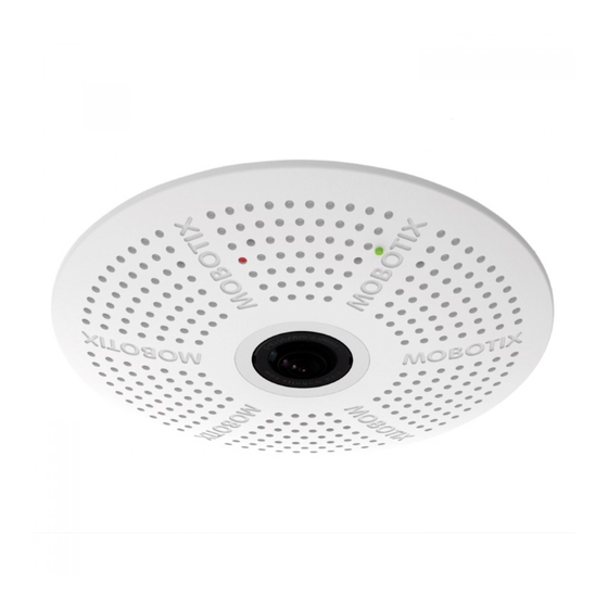
c26 Hemispheric
c26 Hemispheric
All manuals and user guides at all-guides.com
Mx-c26A with
Mx-c26A with
MxIOBoard-IC
lens B016
lens B036
for signal inputs/outputs
Compact Hemispheric Camera
(accessory)
for Ceilings
MOBOTIX 6MP camera for unobtrusive indoor applications,
• Mx6 system platform with H.264 and ONVIF compatibility
available as Day or Night version with MX-B016
• Includes MxAnalytics video analysis tools out-of-the-box
(Hemispheric) or MX-B036 (103°) lens.
• Recording on internal MicroSD card (SDXC, SDHC installed)
• Audio package variant (with microphone and speaker) available
• Sensor for temperature integrated
• Installation is as simple as installing a ceiling spotlight
More information:
www.mobotix.com > Products > Indoor Cameras > Hemispheric c26
Mx-c26A
32.851-001_EN_05/2017
c26 Standard Delivery
1.1
Item
1.9
1.2
1.1
1.2
1.3
1.8
1.4
1.5
1.6
1.3
1.7
1.8
1.7
1.9
1.4
1.6
1.5
Connection and Initial Operation of the c26
You can find detailed information on the installation
and connections of the c26 in the Q25 Camera Manual
(PDF, available on www.mobotix.com > Support >
Manuals).
Please note that the boot options of this camera have changed compared
to its predecessor (see «Boot Options of the c26» on page 2 ) and the
camera only has one key. Regarding the rest of the initial operation of the
c26, please see the Q25 Camera Manual in Chapter 3, «Initial Operation» .
Key
Use a suitable device for operating the camera key (e.g., an opened paper
Power/Status
Recording
clip).
Inserting/Exchanging the SD Card
All camera models can use the integrated MicroSD card (SDXC) to record video data. In order to exchange the MicroSD card, please proceed as outlined in
the following instruction. For information on reliable SD cards, please see the MOBOTIX website www.mobotix.com > Support > MxMedia Library >
Planning in the document MicroSD Card Whitelist for MOBOTIX Cameras . If the camera has not yet been installed, skip step 1.
Caution:
In order to avoid damage from electrostatic discharge, you should touch a grounded device before opening the housing of the camera (e.g.,
the blank metal at the back of a computer). This will remove any static electricity that may have built up.
4. Remove/insert SD card
1. Remove camera, remove cables
If a MicroSD card has been installed, gently press
Pull the camera from its position by gently pulling
with your finger as indicated by the arrow until
the camera downward on one side, then the other
you hear a click . Then release the SD card. The
side.
Take care to NOT let the spring clips snap
card is protruding slightly and can be easily
forward (this may hurt you!).
Remove all cables
removed.
that are attached to the connectors on the back side.
Insert the new MicroSD card and gently press
2. Locate the locks
with your finger as indicated by the arrow until
you hear the click .
In order to remove the back plate, you will need to
push the delivered disassembly tool (item 1.9) into
5. Attach back plate
the three holes on the back one after the other to
Make sure that the SD card is properly locked
release the locks (see red circles in figure).
in place, since the card can be damaged oth-
erwise.
Begin by inserting the wide lock (next
to the SD card) into the camera housing as
shown. From the factory, the lock and the cor-
responding slot are highlighted by
3. Remove back plate
Make sure that the two other locks are also
properly positioned, then press the back plate
Insert the disassembly tool into a lock and press
into its seat until you hear all three locks click
firmly until you feel a perceptible resistance
1
.
into place.
1
6. Re-connect the cables
Insert the Ethernet cable and – if installed – the
USB cable into the corresponding sockets and
secure the connectors using the blue bayonet
catches.
2
Press the spring clips back and insert the
Gently push against the nearest spring clip to push
camera into its original mounting position
the lock out of its seat and to lift the back plate
2
(see «Installing the c26» ).
from the housing
.
To finish, make sure that the camera image is properly aligned: If required,
Repeat the process for the two other locks and
cautiously turn the camera to adjust image alignment.
cautiously lift the back plate from the housing.
Installing the MxIOBoard-IC
For the c26, you can use the optionally available MxIOBoard-IC to attach external sensors using the signal inputs
and to switch other devices via the signal outputs.
1. Insert the MxIOBoard-IC
2. Attach the connection cables
On the back of the camera, remove the sticker
Attach the connection wires as shown in the terminal connector overview.
that protects the receptacle and the camera's
interior from collecting dirt (see red arrow in
figure to the right).
Carefully push the module board onto the
receptacle.
When attaching the connection wires to the
MxIOBoard-IC, make sure the wires are guided
to the module without tension (you could apply
a cable tie and tie the wires to the network
cable, for example).
Installing the c26
Use the drilling template on the back for this purpose (red circle) or draw a circle with 105 mm/4.13 in diameter for the
cut-out. Cut out the hole for the camera, then guide the Ethernet cable and any other cables you want to attach to the
camera through the hole.
1. Connect the cables
2. Install the c26
Insert the cables into the appropriate connec-
Press the spring clips back and insert the c26
Ethernet
tors and fasten them using the blue bayonet
into the hole for the camera. The spring clips
"Up"
catches.
will snap outwards, thus firmly holding the
camera in place.
Make sure that the camera points into the desired
direction: The icon on the back (black arrow)
Make sure that you only press back the spring
shows the "up" direction of the image.
clips as shown in the image. Do not press them
back any further as the springs may snap out
USB
of their fixtures otherwise.
Removing the c26
1. Pull out the camera
2. Remove the cables
Pull the camera from its position by gently pulling the camera downward
Remove the cables coming from the building (network cable, USB cable
on one side, then the other side.
Take care to NOT let the spring clips
and signal input/output wires). Pull out the camera.
snap forward (risk of injury!).
Count Part Name
1
Housing (installed)
1
Back plate with spring clips (installed)
1
Main board with lens MX-B016 or MX-B036
(installed)
2
Bayonet catch, blue (installed)
1
USB plug, blue (installed)
1
Ethernet plug, blue (installed)
1
Ethernet patch cable, 50 cm/19.7 in, black
1
MicroSD card pre-installed (SDHC installed, SDXC
supported)
1
Disassembly tool
color mark
.
Terminal Connectors
MxBus functionality is only available with a later hardware
release of the camera.
Output 1 A
Relay
–
pot.-
Output 1 B/GND
free
Output 1
12 V
Output 1 12 V
–
Out-
puts
Output 2 A
Relay
–
pot.-
Output 2 B/GND
free
Output 2
12 V
Output 2 12 V
–
Input 1 –
Input 1 +
Inputs
Input 2 –
Input 2 +
Advertisement

Related Manuals for Mobotix c26 Hemispheric


Summary of Contents for Mobotix c26 Hemispheric
- Page 1 For information on reliable SD cards, please see the MOBOTIX website www.mobotix.com > Support > MxMedia Library > Planning in the document MicroSD Card Whitelist for MOBOTIX Cameras . If the camera has not yet been installed, skip step 1.
- Page 2 MOBOTIX AG registered in the European Union, the U.S.A., and other countries • Information subject to Fax: +49 6302 9816-190 change without notice • MOBOTIX does not assume any liability for technical or editorial errors or omissions sales@mobotix.com contained herein • All rights reserved • © MOBOTIX AG 2017 www.mobotix.com...
Need help?
Do you have a question about the c26 Hemispheric and is the answer not in the manual?
Questions and answers