Carel ultimateSAM User Manual
Direct steam humidification system
Hide thumbs
Also See for ultimateSAM:
- User manual (42 pages) ,
- User manual (52 pages) ,
- User manual (56 pages)
Table of Contents
Advertisement
Available languages
Available languages
Quick Links
Advertisement
Chapters
Table of Contents

Related Manuals for Carel ultimateSAM


Summary of Contents for Carel ultimateSAM
- Page 1 Sistema di umidifi cazione ultimateSAM Direct Steam Humidifi cation System Manuale d’uso User manual NO POWER & SIGNAL CABLES TOGETHER READ CAREFULLY IN THE TEXT! I n t e g r a t e d C o n t r o l S o l u t i o n s & E n e r g y S a v i n g s...
- Page 3 CAREL Industries o le sue fi liali/affi liate siano state avvisate della possibilità di danni.
-
Page 5: Table Of Contents
La valvola di regolazione vapore perde .............20 L’umidità supera il setpoint ................20 L’umidità non raggiunge il setpoint .............20 Formazione di condensa in condotta ............21 Perdita di vapore da/attraverso il sifone ............21 7. MANUTENZIONE “ultimateSAM - user” +0300070IE - rel. 1.0 - 23.05.2013... -
Page 7: Introduzione E Assemblaggio
23.0 ( 51) le altre sezioni di questo manuale per i dettagli sugli altri componenti SATA*LI300 10.0 ( 22) 24.5 ( 54) del sistema ultimateSAM, come ad esempio le valvole, gli scaricatori di SATA*H300 10.5 ( 23) 28.0 ( 62) condensa, ecc. -
Page 8: Dimensioni E Pesi Del Distributore Sa0 (Single-Pipe)
1.4 Assemblaggio del telaio, (Single-pipe) 1.4.1 Assemblaggio del telaio, versioni SAB/SAT I distributori ultimateSAM in versione SA*****2** sono forniti con un telaio da assemblare, che consiste dei seguenti componenti: “Y” N. 2 supporti inferiori (a) (Nel caso in cui si debba installare un sifone di scarico all’interno della condotta sotto al collettore... -
Page 9: Assemblaggio Versioni Sa0 (Single-Pipe)
Fig. 1.e O-ring Fig. 1.f 1.4.2 Assemblaggio versioni SA0 (single-pipe) I distributori ultimateSAM in versione SA0******* sono forniti con un telaio da assemblare, che consiste dei seguenti componenti: Fig. 1.j Fig. 1.k • collettore comprensivo di fl angia di appoggio;... -
Page 10: Posizionamento
Prevedere i rinforzi appropriati se necessario. Le tabelle pesi sono disponibili alla sezione 9.1 di questo manuale. Centrare al meglio possibile il distributore all’interno della condotta. “ultimateSAM - user” +0300070IE - rel. 1.0 - 23.05.2013... -
Page 11: Montaggio Modelli Sab/Sat
Nota: l’adattatore di ingresso, la valvola di regolazione, l’attuatore, lo scaricatore di condensa e il fi ltro mostrati sopra sono disponibili opzionalmente. I sifoni di scarico non fanno parte del sistema ultimateSAM. “ultimateSAM - user” +0300070IE - rel. 1.0 - 23.05.2013... -
Page 12: Distanze Minime Da Rispettare Sa0 (Single-Pipe)
Portata eff ettiva singola lancia ≤ 50kg/h (110lb/h) -> H=150mm (5.9in) Minima altezza AHU: 300mm (11.8in) Portata eff ettiva singola lancia > 50kg/h (110lb/h) -> H=200mm (7.9in) Minima altezza AHU: 400mm (15.8in) “ultimateSAM - user” +0300070IE - rel. 1.0 - 23.05.2013... -
Page 13: Portata Di Vapore Delle Lance
Le lance che compongono l’ultimateSAM sono di due diversi diametri. Portata eff ettiva singola lancia ≤ 50kg/h (110lb/h) Nella confi gurazione di tipo “S” (6° digit del codice ultimateSAM) le H=150mm (5.9in) L=420mm (16.5in) lance hanno diametro di 35mm (1.37”), per aumentare la portata della Minima altezza AHU: 720mm (28.3in) -
Page 14: Connessioni Ingresso Vapore
3”. 2.1.2 Adattatori ingresso vapore per SA0 (single-pipe) L’ultimateSAM SA0 è dotato di ingresso vapore con diametro 1 “ di tipo GAS Fig. 2.a o 1 ½ ” tipo NPT (mercato Americano). Quindi nel caso di alimentazione con vapore in pressione non è... -
Page 15: Installazione Degli Adattatori Di Ingresso
2.3 Connessione di ingresso del vapore tra ultimateSAM e fl angia della valvola SAKI****** Per l’ultimateSAM sono previsti dei kit di connessione tra l’ingresso del vapore del distributore e la fl angia della valvola. Questi kit variano a seconda della connessione dell’ingresso vapore del distributore e della DN delle valvole. -
Page 16: Connessioni Scarico Condensa
È necessario installare un sifone sulla linea di scarico collegata alla connessione da ¾” posizionata sul fondo di ogni collettore. Questa Per le applicazioni nelle quali l’ultimateSAM è alimentato con vapore ha un fi letto maschio ¾” NPT per il mercato nordamericano e ¾” Gas pressurizzato, è... -
Page 17: Drenaggio Sulla Linea Di Ingresso Per Distributori Alimentati
La tabella 3.b fornisce una lista completa di tutti i fi ltri, separatori e scaricatori di condensa disponibili per l’uso con il distributore ultimateSAM. La tabella indica inoltre per ognuno degli accessori le dimensioni e il tipo di connessione. Connessioni ingresso/scarico... - Page 18 ‡-ˆ O.D. mm (in) 10= 10 mm (0.40) O.D. ‰ Mercato Other / Altri (GAS) North America (NPT) Š Libero Tab. 3.d Fig. 3.l Fig. 3.h “ultimateSAM - user” +0300070IE - rel. 1.0 - 23.05.2013...
-
Page 19: Connessioni Alimentazione Vapore
Gli attuatori e le valvole sono venduti tubazioni di collegamento al distributore ultimateSAM. Nel caso di valvole separatamente. -
Page 20: Connessione Della Linea Di Vapore In Pressione A Un Distributore Ultimatesam
Installare la prolunga sul collettore, se necessario. Nota: i sifoni mostrati sopra non fanno parte del sistema ultimateSAM. Fig. 4.c “ultimateSAM - user” +0300070IE - rel. 1.0 - 23.05.2013... -
Page 21: Funzionamento
5. FUNZIONAMENTO Il sistema di umidifi cazione ultimateSAM distribuisce vapore in una Nel caso di alimentazione con vapore a pressione atmosferica condotta per il trattamento dell’aria. Il controllo della portata di vapore (umidifi catore), La portata è determinata dal carico richiesto immessa in condotta dipende dal tipo di alimentazione usato, che può... -
Page 22: Formazione Di Condensa In Condotta
8.1 Kit piedistallo pe r SAB* / SAT* 8.2 Kit collettore orizz ontale (ingresso vapore - scarico condensa) per SAB* / Kit piedistallo per aumentare la distanza della base dell’ultimateSAM dalla SAT* condotta. Nella fi g.8.a il piedistallo cod. SAKS010000 è mostrato in due... -
Page 23: Kit Distributori Verticali Per Sab* / Sat
SAT* Kit telaio utilizzabile sia come spalla (lato destro o lato sinistro) sia come telaio traversa nel caso dell’ultimateSAM con ingresso vapore dal collettore in basso (SAB*). Esempio: il kit SAKFF0G000 è una spalla da 1305 mm con 17 fori, può essere utilizzata come: •... -
Page 24: Kit Anelli Di Fi Ssaggio Per Sab
Flangia DN 40 Tubo fi lettato 1” Flangia DN 50 Flangia DN 65 Tubo fi lettato 2” ‰ Mercato: 0 = Altri U = U.S. Tab. 8.g Fig. 8.k Fig. 8.i “ultimateSAM - user” +0300070IE - rel. 1.0 - 23.05.2013... -
Page 25: Kit Scaricatore Condensa Secchiello Rovescio
Tab. 8.k • Informazioni ottenute da Sauter S.p.a Ogni kit SAKU0*LI*0 include: • il tubo di distribuzione • 1pz O-ring • bulloni per il fi ssaggio del distributore al collettore Fig. 8.m “ultimateSAM - user” +0300070IE - rel. 1.0 - 23.05.2013... - Page 26 Procedura di installazione SA0 - collettore esterno UTA - con kit copertura parete UTA Descrizione della procedura di installazione dell’ultimateSAM in versione SA0* (single-pipe), con collettore esterno all’unità di trattamento aria e installazione del kit di copertura parete interna UTA.
- Page 27 Applicare il kit di copertura parete UTA per SA0 (non in dotazione, vendibile separatamente): SAKL000000 Installazione del Kit di scarico condensa per SA0 (single-pipe) Installazione del Kit scaricatore termostatico per SA0 (single-pipe) (opzionale, venduto separatamente) SACK*S10*0 (opzionale, venduto separatamente) SAKT*H00*0 “ultimateSAM - user” +0300070IE - rel. 1.0 - 23.05.2013...
- Page 28 Note “ultimateSAM - user” +0300070IE - rel. 1.0 - 23.05.2013...
- Page 29 The technical specifi cations shown in the manual may be changed without prior warning. The liability of CAREL Industries in relation to its products is specifi ed in the CAREL Industries general contract conditions, available on the website www.carel.
- Page 31 Steam valve will not open ..................21 Steam valve will not close...................21 Steam valve is leaking ...................21 Humidity exceeds set point ................21 Humidity remains below set point ...............21 Condensate in duct ....................22 Steam leaks from P-traps..................22 “ultimateSAM - user” +0300070IE - rel. 1.0 - 23.05.2013...
-
Page 33: Introduction And Assembly
202.5 (446) locations, see the “Technical specifi cations” manual. See other sections of SATA*SI3*0 10.0 ( 22) 23.0 ( 51) this manual for details on other ultimateSAM items, such as valves and SATA*LI3*0 10.0 ( 22) 24.5 ( 54) traps. -
Page 34: Dimensions And Weights Of The Sa0 (Single-Pipe) Distributor
Tab. 1.d For other distances and measurements relating to the distributor see the “Technical specifi cations” manual. See the remaining sections of this manual for details on the other components of the ultimateSAM system. 82.5 mm (3.25 in) 37.5 mm 1.3 Opening the packaging... -
Page 35: Assembling The Frame, Sa0 (Single-Pipe) Versions
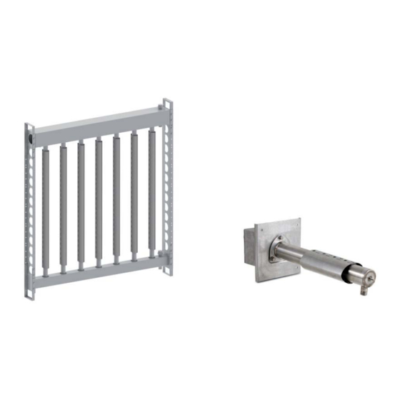
Fig. 1.f 1.4.2 Assembling the frame, SA0 (single-pipe) Fig. 1.j Fig. 1.k versions The ultimateSAM version SA0******* distributors are supplied with a frame to be assembled, which comprises the following components: • manifold with support fl ange • upright •... -
Page 36: Positioning
Positioning BEST: locate distributor far enough from fan to avoid turbulence. • Determine the proper position for the ultimateSAM distributor in the Maintain adequate evaporation distance. duct or AHU. (Fig.1.j) Most steam absorption problems are the result of GOOD: provided there is enough distance from the distributor to the improper positioning. -
Page 37: Mounting Sab/Sat Models
Nota: The inlet adapter, control valve, actuator, trap, and strainer elements supplied; shown above are available as options. The “P” drains are not If necessary, secure the end of the upright. provided as part of the ultimateSAM system. “ultimateSAM - user” +0300070IE - rel. 1.0 - 23.05.2013... -
Page 38: Sa0 (Single-Pipe) Minimal Clearances
Eff ective single upright fl ow-rate ≤ 50kg/h (110lb/h) H=150mm (5.9in) L=250mm (9.8in) Minimum AHU height: 400mm (15.8in) Eff ective single upright fl ow-rate > 50kg/h (110lb/h) H=150mm (5.9in) L=250mm (9.8in) Minimum AHU height: 450mm (17.7in) “ultimateSAM - user” +0300070IE - rel. 1.0 - 23.05.2013... -
Page 39: Upright Steam Fl Ow-Rate
“S” confi guration (6th digit of the ultimateSAM code) the diameter of the uprights is 35 mm ( 1.37”), to increase fl ow-rate on single uprights there is also the “L” confi guration (6th digit of the ultimateSAM code) in which the diameter of the uprights is 45 mm ( 1.77”). -
Page 40: Steam Inlet Connections
2.1.2 Steam inlet adapters for SA0 (single-pipe) The ultimateSAM SA0 has a steam inlet with 11/2 “GAS or 1 ½ ” NPT (American market) fi tting. When supplied with pressurised steam no adapters need to be used, simply connect the steam inlet on the manifold to a 11/2 “ GAS (1 ½... -
Page 41: Installing Inlet Adapters
2.3 Steam inlet connection between ultimateSAM and valve fl ange (SAKI******) Connection kits are available for ultimateSAM between the distributor steam inlet and the valve fl ange. These kits vary depending on the distributor steam inlet connection and valve nominal diameter. -
Page 42: Drain Connections
North American markets and ¾” Gas for the other regions (for the SA0 For installations in which the ultimateSAM distributor is supplied with single-pipe: ½“ GAS or ½“ NPT). Given the minimal pressure inside the pressurized steam, a trap and strainer are required at the inlet of the header, a P-trap is generally suitable for the header drains. -
Page 43: Inlet Drains For Distributors Connected To Atmospheric Steam Supplies
SAKT When used with an atmospheric humidifi er, as shown in (Fig.3.e and Fig. 3.f ), an inlet trap may not be needed on the ultimateSAM distributor. In a typical installation, the condensate in the connecting hose drains back to the humidifi er. In special situations when the condensate cannot drain ... -
Page 44: Modalità Di Scarico Condensa Per Sa0 (Single-Pipe) (Opzionali Venduti Separatamente)
10= 10 mm (0.40) solution, the quick coupling supplied with the thermostatic steam trap ‰ Region Other (GAS) is not needed. North America (NPT) Š Free Tab. 3.d Fig. 3.p Fig. 3.l “ultimateSAM - user” +0300070IE - rel. 1.0 - 23.05.2013... -
Page 45: Steam Supply Connections
A control valve is needed to regulate the fl ow of pressurized steam Nota: For fl anged control valves, the installer must provide the to an ultimateSAM distributor. Actuators for the control valve are appropriate fi ttings and piping to connect the valve to the sold separately. -
Page 46: Connecting Pressurized Steam To An Ultimatesam Distributor
Attach the optional actuator, SAKA******, to the ‚ control valve. Nota: The adapters and steam hoses shown above are available as • options. The “P” drains are not provided as part of the ultimateSAM • Connect the valve/actuator assembly to the inlet adapter on the system. -
Page 47: Operation
All of the steam generated by the controlled depends upon whether the steam comes from a pressurized humidifi er is discharged by the ultimateSAM distributor into the duct or source or an atmospheric source. For pressurized steam supplies, the AHU. -
Page 48: Condensate In Duct
If there is with each of these devices. These accessories should be inspected at evidence of a steam leak at one of the static seals, contact CAREL. least once a year. For systems in which the inlet pressure to the control valve is greater than 0.7 bar (10 psig), more frequent inspections of the... -
Page 49: Uprights Kit For Sab* / Sat
/ SAT* Frame kit used either as a shoulder (right- or left-hand side) or as a cross- piece for ultimateSAM with bottom steam feed (SAB*). Example: kit SAKFF0G000 is a 1305 mm shoulder with 17 holes, and can be used as: •... -
Page 50: Retainer Ring Kit For Sab
U = U.S. Threaded pipe 1” Tab. 8.i Flange DN 50 Flange DN 65 Threaded pipe 2” ‰ Region: 0 = Other U = U.S. Tab. 8.g Fig. 8.k Fig. 8.i “ultimateSAM - user” +0300070IE - rel. 1.0 - 23.05.2013... -
Page 51: Inverted Bucket Condensate Drain Kit
The actuator can be installed in any position between vertical (best) and horizontal. • Information provided by Sauter S.p.a Each SAKU0*LI*0 kit includes: • upright; • 1 O-ring; • bolts for fastening the upright to the manifold. Fig. 8.m “ultimateSAM - user” +0300070IE - rel. 1.0 - 23.05.2013... - Page 52 SA0 installation procedure - manifold outside of AHU - with AHU wall cover kit Description of the installation procedure for ultimateSAM version SA0* (single-pipe), with manifold outside of the air handling unit and installation of the wall cover kit inside the AHU.
- Page 53 Apply the AHU wall cover kit for SA0 (not supplied, available separately): SAKIL00000 Installation of the condensate drain kit for SA0 (single-pipe) Installation of the thermostatic drain kit for SA0 (single-pipe) (optional, sold separately) SACK*S10*0 (optional, sold separately) SAKT*H00*0 “ultimateSAM - user” +0300070IE - rel. 1.0 - 23.05.2013...
- Page 54 Note “ultimateSAM - user” +0300070IE - rel. 1.0 - 23.05.2013...
- Page 56 Agenzia / Agency: CAREL INDUSTRIES HQs Via dell’Industria, 11 - 35020 Brugine - Padova (Italy) Tel. (+39) 0499 716611 - Fax (+39) 0499 716600 carel@carel.com - www.carel.com...
Need help?
Do you have a question about the ultimateSAM and is the answer not in the manual?
Questions and answers