Table of Contents
Advertisement
Quick Links
VentCool
ITEMS INCLUDED (Generation 3):
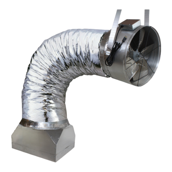
• Fan assembly with electrical control box
• Duct tape (30 ft.)
• 7 ft. of acoustically insulated fl exduct (20" diameter)
• 20 ft. of 1¾" polypropylene webbing
• AirLoc™ Gravity Backdraft Damper; Backdraft
Damper Transition Collar; and, ¼" Phillips head
screws (12)
• Fan Collar
• White Cube Core Grille & White Phillips head
screws (8)
• Wood screws (8)
• Control Package, including: Control box; Wall
Switch with Mounting Bracket and Orange CAT-5
cable (50 ft.)
This device MUST be installed by a qualifi ed agency in accordance with the manufacturer's installation instructions. The defi nition of
a qualifi ed agency is: any individual, fi rm, corporation or company which either in person or through a representative is engaged
in, and is responsible for, the installation and operation of HVAC appliances, who is experienced in such work, familiar with all the
precautions required, and has complied with all the requirements of the authority having jurisdiction.
Installed By:
INSTALLATION MANUAL
2.4, 3.4 & 4.9
®
WHOLE HOUSE FAN
Please retain these instructions after installation.
Phone:
www.fi eldcontrols.com
SUPPLIES NOT INCLUDED & REQUIRED TOOLS:
• Phillips head screw driver
• Socket wrench with ½" socket
• Scissors or Knife
• Pliers
• Drywall Cutter
• Cordless screwdriver with Phillips head &
miscellaneous drill bits
• High quality latex caulk
• Lumber matching dimensions of the attic
joists (e.g. 2"x6", 2"x8", etc.) and cut to fi t
according to the INSTALLATION: FRAMING
section.
• At least 6 additional wood screws
• A ladder
Installation Date:
P/N 780100500 05/19 Rev B
Advertisement
Table of Contents

Related Manuals for Field Controls VentCool 2.4


Summary of Contents for Field Controls VentCool 2.4
- Page 1 INSTALLATION MANUAL VentCool 2.4, 3.4 & 4.9 ® WHOLE HOUSE FAN SUPPLIES NOT INCLUDED & REQUIRED TOOLS: ITEMS INCLUDED (Generation 3): • Phillips head screw driver • Fan assembly with electrical control box • Socket wrench with ½” socket • Duct tape (30 ft.) •...
-
Page 2: Safety Considerations
INSTALLING IT PERMANENTLY. INSTALLING IT PERMANENTLY. The Ventcool Whole House Fan by Field Controls is shipped in one box and inside this box are three indi- vidual boxes or packages separating the three main components of this system. The three main components are: Fan Assembly, Interconnecting Flex Duct and Damper Assembly. -
Page 3: Handling Instructions
ELECTRICAL REQUIREMENTS The VentCool 2.4, 3.4 & 4.9 models requires a 120 volt, 15 amp uninterrupted electricity supply. We strongly The VentCool 2.4, 3.4 & 4.9 models requires a 120 volt, 15 amp uninterrupted electricity supply. We strongly recommend providing a dedicated circuit for this fan. -
Page 4: Ventilation Requirements
Venting requirements vary by fan. We recommend a minimum of 1 sq. ft. of “net free” ventilation area per 500 cfm at a fan’s highest speed. Therefore, the VentCool 2.4, 3.4 and 4.9 Whole House Fans Therefore, the VentCool 2.4, 3.4 and 4.9 Whole House Fans require a minimum square feet of net free ventilation area for proper operation. - Page 5 “box” between the framing in the ceiling and to create an opening into the attic. The fan’s backdraft damper has been designed to fi t within a 14½” x 22½” ceiling opening, for VentCool 2.4 (See Figure 1A) and 22½” x 26½” ceiling opening, for VentCool 3.4 &...
- Page 6 From below, cut out the drywall inside the framed box to create an opening to the attic. To know where to cut, use a stud fi nder to locate the studs from below or drill pilot holes from above. In this confi guration, a notch will need to be cut in the Grille in order to accomodate the center joist running across the opening.
- Page 7 Backdraft Damper Orientation Note The ideal orientation of unit’s backdraft damper is level within the framing. If necessary, however, the damper can be installed at a slight angle within the following constraints: As shown in Figure 5 at right, the damper has two distinct axes: The “Y”...
- Page 8 INSTALLATION: FAN & DUCT The next step in this fan’s installation is to hang the fan assembly from the attic’s rafters, and to attach it to the backdraft damper using the provided ductwork. Figure 8 below shows the fan assembly, ductwork, and back- draft damper as they should appear when fully installed.
- Page 9 Next, slide one end of the fl exible ductwork over the backdraft damper’s transition collar and secure it thereto into place by sandwiching ductwork between backdraft damper collar and sheet metal ring using sheet metal screws, as shown at right in Figure 10. If needed, the backdraft damper transition collar can be rotated to better align the hooks and latches.
- Page 10 INSTALLATION: WIRING & CONTROLS The fi nal step in this fan’s installation is to install its controls. The standard control package included with this fan contains: the control box; 1 hardwired wall switch; 1 mounting bracket for the wired switch and 50 ft. of orange CAT5 cable.
- Page 11 FIGURE 15: Wall Switch DIP Switch Settings (Rear Surface of Display Switch) Figure 16 shows the generic wiring schematic of the VentCool 2.4, 3.4 and 4.9 units. FIGURE 16: VentCool 2.4, 3.4 & 4.9 Wiring Diagram page 11 of 16...
-
Page 12: Start-Up And Operation
RJ45 port. Then, run the cable to the fan’s control box and connect its free end to the blue RMT port. Field Controls remote control transmitters and receivers are pre-merged at our factory. They may, however, become unmerged prior to installation. A remote control transimitter that has become unmerged from its receiver will not be able to control the fan. -
Page 13: Important Operating Tips
If the damper fl aps do not open or close, visually inspect the damper for any debris obstructing their movement. • If the steps above do not work, contact Field Controls Tech Support at 800.742.8368 or fi eldtec@fi eldcontrols. com for further assistance. -
Page 14: Specifications
SPECIFICATIONS TABLE 1 *Air fl ow and sound is infl uenced by installation, duct alignment and air door angle. ** Some models of ventCool are shipped with 1/3 HP ECM Motors TABLE 2 *Due to our continual product improvement eff orts, performance ratings and specifi cations are subject to change without notice. - Page 15 Figure 18 Spare Parts page 15 of 16 P/N 780100500 05/19 Rev B...
- Page 16 This manual may be downloaded and printed from the Field Controls website (www.fi eldcontrols.com) This manual may be downloaded and printed from the Field Controls website (www.fi eldcontrols.com) WARRANTY WARRANTY For warranty information about this or any Field Controls product, visit: For warranty information about this or any Field Controls product, visit: www.fi...
Need help?
Do you have a question about the VentCool 2.4 and is the answer not in the manual?
Questions and answers