
Related Manuals for Pulsar BLACK POWER PSBEN 2012C


Summary of Contents for Pulsar BLACK POWER PSBEN 2012C
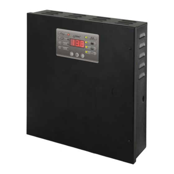
- Page 1 PSBEN 2012C v.1.1 PSBEN 13,8V/2A/17Ah/EN Buffer, switch mode power supply unit. Edition: 6 from 02.02.2015 Supercedes edition: 5 from 18.06.2014 LED Version...
-
Page 2: Table Of Contents
BLACK POWER www.pulsar.pl PSBEN2012C TABLE OF CONTENTS 1. PSU FEATURES..................................4 2. FUNCTIONAL REQUIREMENTS OF THE PSU COMPLIANT WITH THE EN 50131-6 STANDARD....5 3. TECHNICAL DESCRIPTION............................. 6 3.1 G ................................ 6 ENERAL DESCRIPTION 3.2 B . - Page 3 BLACK POWER www.pulsar.pl PSBEN2012C 8. TECHNICAL PARAMETERS............................31 13. E ............................31 ABLE LECTRICAL PARAMETERS 14. M ............................. 32 ABLE ECHANICAL PARAMETERS 15. S ................................ 32 ABLE AFETY OF USE 9. TECHNICAL INSPECTIONS AND MAINTENANCE....................33...
-
Page 4: Psu Features
BLACK POWER www.pulsar.pl PSBEN2012C 1. PSU features. EN50131-6 compliance, 1÷3 grades and II jumper selectable battery charging current environmental class 0,2A/0,6A/1A/1,5A mains supply of 230VAC remote battery test (additional module required) uninterrupted voltage of 13,8VDC ... -
Page 5: Functional Requirements Of The Psu Compliant With The En 50131-6 Standard
BLACK POWER www.pulsar.pl PSBEN2012C 2. Functional requirements of the PSU compliant with the EN 50131-6 standard. Requirements of EN 50131-6 Functional requirements PSBEN2012C Grade 1 Grade 2 Grade 3 EPS network absence Low battery voltage Protection against complete battery discharge... -
Page 6: Technical Description
(color: RAL 9005 - black) with battery space for a 17Ah/12V battery. It is fitted with micro switches indicating unwanted door opening (front panel) and detachment from the mounting surface. DOPTIONAL POWER SUPPLY CONFIGURATIONS: (visualization available at www.pulsar.pl) 1. Buffer power supply PSBEN 13,8V/2x1A/17Ah/INTERFACE - PSBEN 2012C + LB2 2x1A (AWZ585,AWZ586)+17Ah+INTERFACE 2. -
Page 7: Block Diagram
BLACK POWER www.pulsar.pl PSBEN2012C 3.2 Block diagram. The PSU is manufactured based on a high-duty system of DC/DC converter. The microprocessor system is responsible for full diagnostics of the PSU and battery parameters. Fig. 1. Block diagram of the PSU. -
Page 8: Description Of Psu's Components And Connectors
BLACK POWER www.pulsar.pl PSBEN2012C 3.3 Description of PSU’s components and connectors. Table 1. Elements of the PSU pcb (see Fig. 2). Element no. Description PANEL – optical indication connector ; pin - configuration of battery protection UVP battery protection (disconnection) off ... - Page 9 BLACK POWER www.pulsar.pl PSBEN2012C Fig. 2. The view of the PSU’s PCB. Table 2. PSU elements (see fig. 3). Element no. Description Insolation transformer PSU board (see Tab.1, fig.2) TAMPER; micro-switch (contacts) of tamper resistance (NC) fuse in the supply circuit (230V/AC)
-
Page 10: Installation
BLACK POWER www.pulsar.pl PSBEN2012C 4. Installation. 4.1 Requirements. The PSU is to be mounted by a qualified installer, holding relevant permits and licenses (applicable and required for a given country) for 230V/AC in and low-voltage installations. As the power supply is designed for a continuous operation and is not equipped with a power- switch, therefore, an appropriate overload protection in the power supply circuit should be provided. - Page 11 BLACK POWER www.pulsar.pl PSBEN2012C 8. Check the output voltage (the PSU voltage without load and without battery should amount to 13.7V ÷ 13.9V, with a battery or during battery charging process: 11.0V÷13.8V). If the value of the voltage requires adjustment, it should be set with use of the V potentiometer, monitoring the voltage at the AUX output of the PSU.
-
Page 12: Functions
BLACK POWER www.pulsar.pl PSBEN2012C 5. Functions. 5.1 Control Panel. The PSU features a panel with buttons and LED display, enabling reading of all the available electrical parameters. The panel buttons are used to select and confirm the parameters, which should be displayed. -
Page 13: Main Menu
BLACK POWER www.pulsar.pl PSBEN2012C 5.2 Main menu. The PSU is equipped with a menu, which allows to preview the current electrical parameters. The diagram explaining the menu structure is presented below. Fig. 6. The menu of the display. Table 6. The description of display symbols. -
Page 14: Failure History "Flh
BLACK POWER www.pulsar.pl PSBEN2012C Failure history “FLh” 5.2.3 The PSU stores 30 last failures in non-volatile memory, which can be reviewed later. In order to review the failures, use the "<" or ">" button to set the FLh parameter and confirm by pressing "OK". -
Page 15: List Of Failure Codes And Information Messages
BLACK POWER www.pulsar.pl PSBEN2012C - press „<” or „>” button to set the „FLc” parameter on the display „FLc” - press „OK” button - the number 1, indicating the number of failure in the memory (the highest priority), will be displayed. Then, after one second, failure code will be automatically displayed - press „OK”... - Page 16 BLACK POWER www.pulsar.pl PSBEN2012C Table 7. List of PSU failure codes. Technical Failure Additional Information output Additional information code information activation - No AC mains supply AC power fail! EPS FLT fuse failure MAINS - Blown F fuse AUX fuse fail!
-
Page 17: Psu Configuration
BLACK POWER www.pulsar.pl PSBEN2012C 5.3 PSU configuration. The PSU is equipped with a configuration menu that allows to configure the settings by changing or the activation of some of its parameters. The figure illustrating the configuration menu structure is shown below. -
Page 18: Battery Test On/Off „Tst
BLACK POWER www.pulsar.pl PSBEN2012C Battery test ON/OFF „tSt” 5.3.1 The "tSt" function allows to enable or disable the test of the battery (Section 6.3) connected to the power supply. When activated, the battery test occurs automatically if it is not blocked by the control system (section 6.3). -
Page 19: Led Display Dimmer „Dis
BLACK POWER www.pulsar.pl PSBEN2012C LED Display Dimmer „dIS" 5.3.2 LED display dimmer allows to dim the display if no buttons are pressed within 5 minutes.If the display is in the blackout mode, pressing any button will "reactivate" the display. - simultaneously press the „<,>” rightmost and leftmost buttons on the LED panel - the „tSt”... -
Page 20: Setting The Transmission Speed „Trs" Applies To Cooperation With Powersecurity
BLACK POWER www.pulsar.pl PSBEN2012C - press „OK” - the current address of the PSU will be displayed - use the „<” or „>” buttons in order to set the address 1÷ 247 – address of the PSU during the communication with the computer - confirm by pressing „OK”... -
Page 21: Setting The Parity Of The Transmission "Trp" Applies To Cooperation With Powersecurity
BLACK POWER www.pulsar.pl PSBEN2012C Setting the parity of the transmission “trP” 5.3.5 applies to cooperation with PowerSecurity. All the parameters responsible for communication between the PSU and the computer, namely the address, parity and speed should have the same settings for both the PSU and the PowerSecurity program. -
Page 22: Technical Outputs
BLACK POWER www.pulsar.pl PSBEN2012C 5.5 Technical outputs. The PSU feature indication outputs, with galvanic isolation, which change their state if any of the following events occur: EPS FLT - output indicating AC power loss. The output indicates 230V AC power loss. Under normal status (with 230V supply on) the output is closed. -
Page 23: Enclosure Tamper Indication - Tamper
BLACK POWER www.pulsar.pl PSBEN2012C The electrical diagram below shows the way of connecting external devices to the EXT IN input. Outputs such as: OC (open collector), relay may be used as a source of the signal. Fig. 10. Examples of connections. -
Page 24: Overvoltage Protection Of The Psu Output Ovp
BLACK POWER www.pulsar.pl PSBEN2012C 5.8 Overvoltage protection of the PSU output OVP. In case of voltage exceeding 15,5V±0.5V at the switching regulator’s output, the system cuts off the power at the outputs to protect the battery and the receivers from damage. The outputs will be battery-powered. -
Page 25: Reserve Power Supply Circuit
BLACK POWER www.pulsar.pl PSBEN2012C 6 Reserve power supply circuit. The power supply is equipped with intelligent circuits: charging and battery control circuit, whose main task is to monitor the condition of the battery and its connections in the circuit. If the power supply driver detects a malfunction in the battery circuit, appropriate signaling and change in the APS FLT technical output take place. -
Page 26: Standby Time
BLACK POWER www.pulsar.pl PSBEN2012C 6.4 Standby time. Battery-assisted operating depends on battery capacity, charging level and load current. To maintain an appropriate standby time, current drawn from the PSU in battery mode should be limited. Characteristics for a 17Ah/12V SLA:... -
Page 27: Remote Monitoring (Options: Wi-Fi, Ethernet, Rs485, Usb)
BLACK POWER www.pulsar.pl PSBEN2012C 7. Remote monitoring (options: Wi-Fi, Ethernet, RS485, USB). The PSU has been adjusted to operate in a system that requires a remote control of the parameters in a monitoring centre. Transmitting data concerning PSU status is possible due to an additional, external communication module responsible for communication in Wi-Fi, Ethernet or RS485 standard. -
Page 28: The Wi-Fi Wireless Communication
BLACK POWER www.pulsar.pl PSBEN2012C The RS485-WiFi „INTRE” interface is a device used to convert signals between the RS485 bus and the Wi-Fi network. For proper operation, the unit requires an external power supply in the range of 10÷30V DC e.g. drawn from a PSU of the PSBEN series. -
Page 29: Rs485 Network Communication
BLACK POWER www.pulsar.pl PSBEN2012C The RS485-WiFi „INTRW” interface is a device used to convert signals between the RS485 bus and the Wi-Fi network. For proper operation, the unit requires an external power supply in the range of 10÷30V DC e.g. -
Page 30: Powersecurity" Program
BLACK POWER www.pulsar.pl PSBEN2012C 7.5 „PowerSecurity” program. The ”Power Security” program is available at www.pulsar.pl Its detailed description can be found in the manual. „Power Security” is a free computer program for viewing and analyzing the information sent from the PSU installation spots. - Page 31 BLACK POWER www.pulsar.pl PSBEN2012C 8. Technical parameters. Electrical parameters (Table 13). Mechanical parameters (Table 14). Safety of use (Table 15). Table 13. Electrical parameters. PSU type A, protection class 1÷3, II environmental class Mains supply 230V AC 50Hz (-15%/+10%) Current consumption 0,2 A PSU’s power...
- Page 32 BLACK POWER www.pulsar.pl PSBEN2012C - USB-TTL ‘INTU’ interface; USB-TTL communication - RS485 ‘INTR’ interface: RS485 communication - USB-RS485 ‘INTUR’ interface; USB-RS485 communication - Ethernet ‘INTE’ interface; Ethernet communication - WiFi “INTW’ interface; Wi-Fi wireless communication Additional accessories (not included) - RS485-Ethernet “INTRE’ interface; RS485-Ethernet communication - RS485-WiFi “INTRW’...
- Page 33 BLACK POWER www.pulsar.pl PSBEN2012C 9. Technical inspections and maintenance. Technical inspections and maintenance can be performed after disconnecting the power supply from the power network. The PSU does not require any specific maintenance; however, its interior should be cleaned with compressed air if it is used in dusty conditions.
- Page 34 GENERAL WARRANTY CONDITIONS 1. Pulsar (manufacturer) grants a five-year quality warranty for the equipment, starting from the production date. 2. The warranty includes free-of-charge repair or replacement with an appropriate equivalent (selected by the manufacturer) if the malfunction is due to the manufacturer.
Need help?
Do you have a question about the BLACK POWER PSBEN 2012C and is the answer not in the manual?
Questions and answers