Advertisement
Technical
Manual
Table of Contents
Specification.....................................1
Parts List ..........................................2~5
Destination Setting...........................6
Wiring Diagram ...............................7
PCB Assembly .................................8
Schematic Diagram..........................9
Specification
Power Configurations (FTC)
Watts/Channel
Total Harmonic Distortion(20-20kHz, 8 ohms)
Power Output (4 Ohms, 0.09%, THD)
Intermodulation Distortion(60Hz : 7kHz, 4:1)
Dampning Factor(8 ohms)
Amp Gain
Input Sensitivity / Impedance
Frequency Response
Signal to Noise Ratio(IHF A network)
Power Requirement
USA
Europe
Power Consumption
Dimensions (W x H x D)
Panel Height
Weight (net)
10-10 SHINSEN-CHO , SHIBUYA-KU,
TOKYO 150-0045, JAPAN
Quality Uncompromised
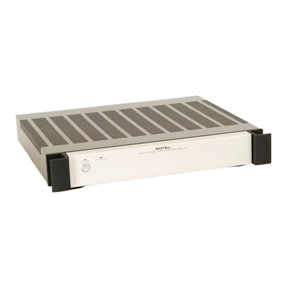
SEVEN CHANNEL POWER AMPLIFIER
7 x 100 watts/ch into 8 ohms
100 watts, all channel driven, with 20KHz filter,
8 ohm load, 20-20kHz, 0.03% THD
< 0.03 %
200 watts
< 0.03 %
400
27.4 dB
1.2 volts / 8.3 k ohms
10 Hz - 80 KHz ( 3dB)
105 dB
120 volts 60 Hz
230 volts 50 Hz
400 watts
70 watts - Idling
3 watts - Standby
432 x 72 x 415 mm
17
60 mm, 2
7.8 kg, 17.2 Lb.
®
RMB-1077
x 2
x 16
inches
1/8
7/8
3/8
inches
3/8
Serial. NO.
Y-385A-0510/pdf
Advertisement
Table of Contents

Related Manuals for Rotel RMB-1077


Summary of Contents for Rotel RMB-1077
-
Page 1: Table Of Contents
Quality Uncompromised ® Technical SEVEN CHANNEL POWER AMPLIFIER RMB-1077 Manual Table of Contents Specification........1 Parts List ..........2~5 Destination Setting......6 Wiring Diagram .......7 PCB Assembly .........8 Schematic Diagram......9 Specification Power Configurations (FTC) 7 x 100 watts/ch into 8 ohms Watts/Channel 100 watts, all channel driven, with 20KHz filter, 8 ohm load, 20-20kHz, 0.03% THD... - Page 2 RMB-1077 Appearance POWER PROTECTION SEVEN CHANNEL POWER AMPLIFIER Please request: When the fault are in the 250A or 250ASP module, replace the module and send back the modules later.
-
Page 3: Parts List 1/2
RMB-1077 Parts List 1/2 SYMBOL PARTS NO. DESCRIPTION 016 X-1415A01-03 PCB ASSY 501 X-1415 PCB ASSY MICA SHEET TBM-51W-15 #9036 D94,95 019 TO-220 LINE FILTER COIL 021 2648701170 L1-7 021 LF-173A00 FILTER COIL IC11-15 031 AD629AN IC (DIFFERENCE AMP) IC19-21... - Page 4 RMB-1077 Parts List 2/2 SYMBOL PARTS NO. DESCRIPTION (R103) 053 CR14-272J-A CARBON RESISTOR 1/4W 2.7K (R103) 053 CR14-472J-A CARBON RESISTOR 1/4W 4.7K R102 053 CR16-333J-A CARBON RESISTOR 1/6W 33K MOF RESISTOR 1WS 120R R101,109 054 1WS120JF MOF RESISTOR 1WS 1K...
- Page 5 Addendum List for Black and Silver RMB-1077 SYMBOL PARTS DESCRIPTION 011 FP-586-B BLACK PANEL ASSY 011 FP-586-S SILVER PANEL ASSY 011 VA3-01A00 H/S PANEL H60 012 RV4-09A00 PUSH BUTTON 14F (BLK) 012 RV4-09A01 PUSH BUTTON 14F (SLV) 034 SEL1124R LED (RED) 1X5...
-
Page 6: Destination Setting
RMB-1077 Destination setting 1. find the Setting Jumper and FUSE in the FL and FR 092 ICEPOWER250ASP. 2. Set the Jumper to the destination country voltage on both PCB's. 3. Replace the fuse value to the destination. T3.15A for 115 V and T2.5A for 230V. -
Page 7: Wiring Diagram
068 C-4586A01 (2P 270mm BRN/BLK) POWER LED X-1438-01 (K102) PROTECTION LED X-1415-01 (D002) 068 C-4586A06 (2P 420mm YEL/BLK) 073 RMB-1077-P#5 (BRN 220mm) X-1415-03 (S1) X-1438-01 (AC1-1) 068 C-4890A01 (BRN) X-1415-03 (S2) X-1415-01 (AC4 -L, N) 068 C-4890A01 (WHT) X-1415-01 (AC4 -L) -
Page 8: Pcb Assembly
RMB-1077 PCB Assembly Output and Protection PCB 016 X-1415A01 - 03 Sub Transformer PCB 016 X-1438A01 -02... -
Page 9: Schematic Diagram
Schematic Diagram RMB-1077...
Need help?
Do you have a question about the RMB-1077 and is the answer not in the manual?
Questions and answers