Advertisement
T echnical
Manual
Table of Contents
Specification......................................1
Parts List ...........................................2~3
Adjustment........................................ 4
Service Note......................................4
Case Outlines....................................5
PCB Assembly ..................................5~10
Schematic Diagram ..........................11~12
Specification
Continuous Power Output Stereo Mode
(20-20 kHz, <0.03%THD)
Continuous Power Output Bridged Mono Mode
(20-20 kHz, < 0.1% THD)
Total Harmonic Distortion
(20Hz-20kHz, 8 ohms)
Intermodulation Distortion
(60 Hz : 7 kHz, 4:1)
Frequency Response (± 1 dB)
Damping Factor (20-20,000 Hz, 8 ohms)
Speaker Impedance (combined load)
Signal to Noise Ratio (IHF A network)
Input Impedance
Input Sensitivity
Auto Turn On Threshold Level (if activated)
Auto Turn Off Delay Time (if activated)
Power Requirements
Power Consumption
Dimensions (W x H x D)
Weight
SHINSEN-BLD. 4F 10-10 SHINSEN-CHO, SHIBUYA-KU,
TOKYO 150-0045, JAPAN
Quality Uncompromised
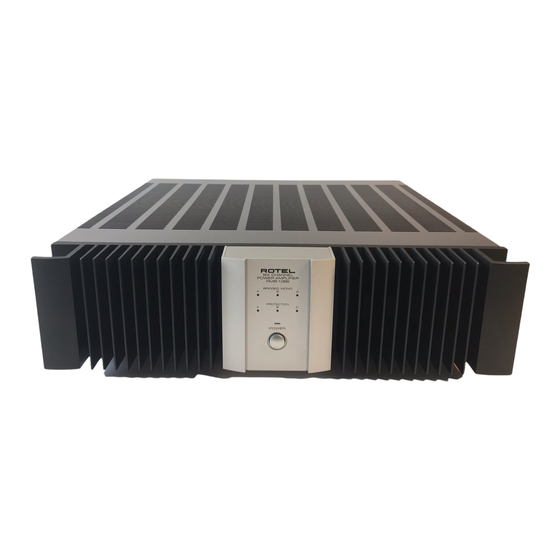
SIX CHANNEL POWER AMPLIFIER
RMB-1066
®
60 watts/ch into 8 ohms
150 watts/ch into 8 ohms
<0.03%
<0.03%
15 Hz-100 kHz
150
Stereo mode : 4 ohms minimum
Bridged Mono mode : 8 ohms minimum
116 dB
22 k ohms
1.5 volt
10 mV input signal
5 minutes with no signal
USA : 115 volts, 60 Hz
Europe : 230 volts, 50Hz
700 Watts
430 x 121 x 435 mm
16
x 4
x 17
in
15/16
3/4
1/8
13.5kg, 29.75 lb
Serial. NO.
Beginning
Y-343A-01035C/S-S
Advertisement
Table of Contents

Related Manuals for Rotel RMB-1066


Summary of Contents for Rotel RMB-1066
-
Page 1: Table Of Contents
Quality Uncompromised ® T echnical SIX CHANNEL POWER AMPLIFIER RMB-1066 Manual Table of Contents Specification........1 Parts List ...........2~3 Adjustment........4 Service Note........4 Case Outlines........5 PCB Assembly ........5~10 Schematic Diagram ......11~12 Specification Continuous Power Output Stereo Mode 60 watts/ch into 8 ohms (20-20 kHz, <0.03%THD) -
Page 2: Parts List
Parts List-1 SYMBOL PARTS NO. DESCRIPTION SYMBOL PARTS NO. DESCRIPTION X-1280 PCB ASSEMBLY C501.502 041 UTES1H100-FB CAPACITOR ELEC.50V10UF D812 034 TRD5.6JST1 ZENER DIODE C503.504 044 S50V330PJ CAPACITOR STYROL 50V330PF K811 067 C-4493A00 SPEAKER TERMINAL C505.506 044 S50V220PJ CAPACITOR STYROL 50V220PF L801.802 021 TRL-331 SPEAKER COIL... - Page 3 Parts List-2 SYMBOL PARTS NO. DESCRIPTION SYMBOL PARTS NO. DESCRIPTION X-1307-05 PCB ASSEMBLY S404 064 C-4660A00 SLIDE SWITCH(SIGNAL SENS.) K431 065 YKB21-5103A MINI JACK T421.422 032 TC536-FG TRANSISTOR(2SC536K-FG) K433 065 YKB21-5103A MINI JACK T423 032 TA608-FG TRANSISTOR(2SA608K-FG) R431 053 CR14-223J-A RESISTOR CARBON 22K U421 031 PC817B...
-
Page 4: Adjustment
Adjustment Instruments : DC milli-meter Notes Prior to Bias Adjustment, run about 5minutes with rated output (8 ohms) And warm up Power Transistor and Heat Sink.Set input off. Step Coupling Location Adjust Adjust for K 3 1 X - 1 2 8 0 -0 1 P CB R5 3 7 K 3 2 X - 1 2 8 0 - 0 1 P CB... -
Page 5: Case Outlines
Case Outline PCB Assembly-1 2SA1943 2SC536K 2SC5200 2SA608K 2SA1016K 2SB631K NJM555D 2SD600K 2SC1941 MPC1237HA... - Page 6 PCB Assembly-2...
- Page 7 PCB Assembly-3...
-
Page 8: Schematic Diagram
Schematic Diagram Channel B Channel A J501 J601 T509 T609 T551 X-1307A01 2SA1016K T651 2SA1016K 2SC536K J505 2SC536K J605 R401 K404 J509 J609 T519 T619 T505 T605 2SC5200 2SC5200 2SA1016K 2SA1016K C407 R407 T615 T515 2SD600K J613 R402 2SD600K J513 100K 50V0.1 Daisy Chain...
Need help?
Do you have a question about the RMB-1066 and is the answer not in the manual?
Questions and answers