Canon VB-C500D Start Manual
Canon security camera user manual
Hide thumbs
Also See for VB-C500D:
- Operation manual (160 pages) ,
- Specifications (2 pages) ,
- Administrator's manual (302 pages)
Table of Contents
Advertisement
Quick Links
Advertisement
Table of Contents

Subscribe to Our Youtube Channel
Related Manuals for Canon VB-C500D


Summary of Contents for Canon VB-C500D
-
Page 1: Network Camera
Network Camera VB-C500D Start Guide Please read carefully this Start Guide and the Operation Guide Especially be sure to read "Safety Precautions" before using the network camera. Keep this guide in a readily accessible location for future reference. -
Page 2: Introduction
Thank you for purchasing Canon Network Camera VB-C500D (hereafter referred to as VB-C500D). This Start Guide describes how to set up and install the VB-C500D. The detailed procedures for using the VB-C500D are explained in the Operation Guide provided on the Setup CD-ROM. Read these guides carefully before using the VB-C500D to ensure that you make the best possible use of this product. -
Page 3: Trademark Notice
Malfunction, failure of VK-Lite or other factors may cause problems, such as recording failure, recorded data corruption or loss. Canon shall have no liability whatsoever for any loss or damages incurred by the user as a result of such problems. -
Page 4: Third Party Software
MPEG-4 standard. Third Party Software The product (VB-C500D and bundled VK-Lite Viewer) contains third party software modules. For detail information, please see ReadMe-E.txt on the supplied Setup CD-ROM. Each module’s license conditions are also available in the License folder on the same Setup CD-ROM. -
Page 5: Table Of Contents
Safety Precautions ... x Maintenance ... xv Chapter 1 Before Use Features of VB-C500D ... 1-2 Bundled Software ... 1-5 VB Initial Setting Tool Ver. 5.0 ... 1-5 VBAdmin Tools Ver. 5.0 ... 1-5 VB-C500 Viewer Ver. 1.0 ... 1-6 Network Video Recorder VK-Lite v2.1 ... - Page 6 Installation Procedure for In-Ceiling with a Ceiling/Wall ... 2-25 Chapter 3 Appendix External Dimension Drawing ... 3-2 VB-C500D ... 3-2 Recessed Mounting Kit SR500-S-VB (Option) ... 3-2 Main Specifications ... 3-3 Input/Output Terminals ... 3-5 External Device I/O Terminals ... 3-5...
-
Page 7: Checking Of Bundled Items
VBToolsInstall.exe : Installer for VB Initial Setting Tool and VBAdmin Tools* VKLiteInstall.exe : Installer for Network Video Recorder VK-Lite* License : Folder containing licenses for the built-in software of the VB-C500D as well as bundled software VK-Lite Sound : Folder containing sample audio files * Check our website for the latest versions of bundled software and operation manuals. -
Page 8: Operation Manuals
Checking of Bundled Items Operation Manuals The VB-C500D comes with Start Guide (this document) and Operation Guide included in the Setup CD-ROM. Start Guide (This Document) The safety precautions to be followed when using the VB-C500D, types of bundled software, operating environment, installation method, initial setting of the camera, installation method, etc., are explained. -
Page 9: How To Read This Document
How to Read This Document In Start Guide and Operation Guide, screens in Windows Vista are mainly used. Unless otherwise specified, the same screens apply to Windows XP. Symbols Used for Safety Precautions In this document, the following symbols are used to indicate important items the user should know to use this product safely. -
Page 10: Safety Precautions
When replacing the fuse only a correctly rated approved type should be used and be sure to re-fit the fuse cover. The AC adapter can be connected to VB-C500D from a standard AC power outlet. Please check your instruction manual to make sure that your VB-C500D is compatible with this adapter. -
Page 11: Canadian Radio Interference Regulations
If such changes or modifications should be made, you could be required to stop operation of the equipment. Canon U.S.A. Inc. One Canon Plaza, Lake Success, NY 11042, U.S.A. Tel No. (516) 328-5600 Canadian Radio Interference Regulations... -
Page 12: Precautions For Installation
For installation or inspection of the VB-C500D, consult/request the store where you purchased the product. • Wire the VB-C500D power supply, network, or other cables safely and securely according to the relevant regulations such as technical standards for electrical installations. -
Page 13: Precautions For Use
Canon will assume no liability for any accident or damage resulting from use of the VB-C500D in the aforementioned devices or systems. • Do not capture the sun, halogen lamps and other very bright light sources or subjects. -
Page 14: Notes On Cleaning
These are support functions for monitoring. They do not guarantee monitoring with very high accuracy, however, as they might not work as accurately as expected under certain conditions. Canon will assume no liability for any accident or damage resulting from use of these functions. -
Page 15: Maintenance
Maintenance Turn off the power before cleaning the camera ( Cleaning of Exterior 1. Dampen a soft cloth with water or diluted neutral detergent and wipe the soiled areas gently. 2. Wipe with a dry cloth. Cleaning of Lens Use a commercial lens cleaner to remove soiling on the lens surface. Scratches on the lens surface may result in undesirable images. - Page 16 Safety Precautions...
-
Page 17: Before Use
Before Use The following explains the features of this camera, bundled software, operating environment, and name and function of each part. -
Page 18: Smart Shade Control
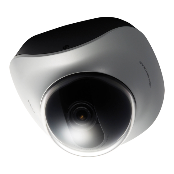
Features of VB-C500D The VB-C500D is a compact network camera for indoor installation integrating camera and server features. Wide-angle Varifocal Lens Equipped with a wide-angle varifocal lens with a wide angle of 82°, F1.1 and optical 2.4x zoom (digital 4x), the VB-C500D achieves video monitoring in wide-ranging applications, including stores and offices, as well as applications in small areas such as at ATM and in elevator halls. - Page 19 In JPEG, image can be distributed in three sizes (640x480, 320x240, 160x120) at the same time. High Quality Video of Moving Subjects The VB-C500D utilizes a progressive-scan CCD to allow for the capture of noise-less, high quality video of moving subjects. Selectable Metering Modes for Various Shooting Condition Image can be captured by switching the metering mode* to one of three options, including Center-weighted, Average and Spot, according to the shooting condition of the camera.
- Page 20 Features of VB-C500D Two-Way Audio (Full Duplex) A microphone or speaker with amplifier can be connected* audio (full duplex) via the viewer* and MIC IN by switching the setting on the setting page ( *1 Microphones and amplifiers are sold separately.
-
Page 21: Bundled Software
VB Initial Setting Tool Ver. 5.0 P. 2-10) VB Initial Setting Tool is for initial setting of the VB-C500D. It is installed from Setup CD-ROM P. 2-4). Users other than Administrators need not install this tool. VBAdmin Tools Ver. 5.0... -
Page 22: Vb-C500 Viewer Ver. 1.0
Bundled Software VB-C500 Viewer Ver. 1.0 VB-C500D Viewer is for displaying video captured by this camera and controlling the camera. Three users can be set according to the camera control rights, including [Administrator], [Authorized Users] and [Guest Users]. This tool is already built into the camera and need not be installed beforehand ( P. - Page 23 PC VK-Lite Storage Server VK-Lite Viewer For VK-Lite, following cameras can also be registered and used. Supported VB-C500D, VB-C60/VB-C60B, VB-C300/VB-C300B cameras VB-C50i/VB-C50iR, VB-C50FSi, VB-C50Fi Note To add a VK-Lite Viewer, you need to purchase an optional "VK-Lite Additional Viewer License".
- Page 24 Bundled Software Key Functional Limitations of VK-Lite and VK-64/VK-16 Category Key functional limitation Maximum number of Camera cameras that can be connection connected Recording format Recording mode Storage server Maximum recording frame rate Maximum video retain period Registration of multiple storage servers* Viewer Number of displayable...
- Page 25 VK-Lite Viewer JPEG/MPEG-4 VB-C500 Viewer Audio Reception (One-way Communication) VB-C500D Microphone (sold separately) Audio from the microphone connected to the VB-C500D can be listened from the viewer speaker. Audio Receive audio from the VB-C500D (one-way communication) Transmit/receive audio (two-way communication)
- Page 26 Bundled Software VK-Lite Viewer Audio Transmission/Reception (Two-way Communication) VK-Lite Viewer VB-C500D JPEG/MPEG-4 Microphone Microphone Network (sold separately) Audio Speaker Speaker (sold separately) Audio can be transmitted/received between the VB-C500D and viewer. PC, speaker and microphone are sold separately. 1-10...
-
Page 27: Operating Environment
Operating Environment For the latest information on this product (firmware, bundled software, operation manuals, operating environment, etc.), visit our website. VB Initial Setting Tool Ver. 5.0, VBAdmin Tools Ver. 5.0, VB-C500 Viewer Ver. 1.0 Windows Vista Home Premium/Business/Enterprise/Ultimate (SP1), Internet Explorer 7.0 Windows Server 2008 Standard Internet Explorer 7.0 OS and browser... - Page 28 Operating Environment *1 Windows Vista and Windows Server 2008 support the 32-bit and 64-bit editions. Other OSs support only the 32-bit edition. *2 External hard disks cannot be used. The optional VK-64/VK-16 v2.1 does not support Windows Vista Home Premium. 1-12...
-
Page 29: Notes On Operating Environment
Notes on Operating Environment Notes on Use When the [Windows Firewall] Function is Enabled When [VB Initial Setting Tool] is started, the [Windows Security Alert] dialog box may appear. If the [Windows Security Alert] dialog box appeared, click [Unblock]. Once this button is clicked, this warning dialog box will no longer appear. If the [Windows Security Alert] dialog box is not displayed, the warning function of the Windows firewall may be disabled. -
Page 30: Notes On Use With Windows Server 2003/Windows Server 2008
Notes on Operating Environment 3. Click the [Add program…] button to add [VB Initial Setting Tool]. Notes on Use with Windows Server 2003/Windows Server 2008 Registering the Camera's Top page as a Trusted Site In Windows Server 2003 and Windows Server 2008, the security level for Internet sites and intranet sites on Internet Explorer is set to [High] by default. - Page 31 Clear the [Require server verification (https:) for all sites in this zone] check box, if currently selected. Enter the IP address of the VB-C500D under [Add this Web site to the zone], and then click [Add] to register the site as a trusted site.
-
Page 32: Notes On Use With Windows Server 2008
Notes on Operating Environment 3. Select [Trusted Sites], and click [Site]. This completes the process of registering the camera's top page as a trusted site. Notes on Use with Windows Server 2008 Enabling the Sound Function to Use Audio In Windows Server 2008, the sound function is disabled by default. If you want to receive audio on VB-C500 Viewer, enable the sound function by following the procedure below. - Page 33 If [Control Panel] is displayed in a classic view, double-click [Sound]. Next, click [Sound]. 3. When the dialog box with the message, [Audio Service is not running] appears, click [Yes]. Finally, the [Sound] dialog box appears. Click the [Playback] tab to confirm that an audio device has been installed.
-
Page 34: Notes On Use With Windows Vista
Notes on Operating Environment Notes on Use with Windows Vista The following restrictions apply when the VB-C500D is used with Windows Vista Home Premium/ Business/Enterprise/Ultimate. Network Video Recorder VK-Lite v2.1 Warning dialog box displayed upon opening of the [Storage Server Settings] dialog box If the User Account Control is enabled in Windows Vista, the User Account Control dialog box appears when the Storage Server Settings tool is started. -
Page 35: Name And Function Of Each Part
Name and Function of Each Part Dome Case/Inner Cover/Camera Interior Notes on Operating Environment Dome case Inner cover Varifocal lens Horizontal field of view 82° Focus lock screw Zoom adjustment knob Rotation lock screw Pan lock screw Tilt lock screw Dome case lock screw 1-19... - Page 36 Notes on Operating Environment Top View of Camera (Without Dome Case) 1-20 Reset switch Turn on the power while pushing this switch. Continue to push the switch for 5 seconds or more to restore all factory settings except for the date and time. The LED becomes lit/unlit according to the status of the camera.
- Page 37 Bottom The MAC address and serial number required in network setting are specified at the bottom of the camera. Write down these information before installing the camera. Notes on Operating Environment Serial number Serial number of this camera. Tripod mounting screw holes MAC address Unique address of this camera.
-
Page 38: Optional Items
Optional Items Purchase options separately as necessary. Audio Interface Cable WA500-VB Use this interface cable to connect the camera to an audio input/output device (speaker, microphone, etc.). Marking band The terminal marked "1" on the marking band (farther away from the cable branching point) is used for audio output, while the unmarked terminal (closer to the branching point) is used for audio input. -
Page 39: I/O Interface Cable Wc500-Vb
Optional Items I/O Interface Cable WC500-VB Use this interface cable to connect the camera to a contact input/output device (sensor, warning lamp, etc.). For details on the external device input/output terminals, refer to P. 3-5. Power Interface Cable WP500-VB Use this interface cable to connect the camera to an optional AC adapter (PA-V17) or external power supply. -
Page 40: Recessed Mounting Kit Sr500-S-Vb
Optional Items Recessed Mounting Kit SR500-S-VB The Recessed Mounting Kit is a dedicated option for VB-C500D. Use example AC Adapter PA-V17 Use this adapter when a PoE HUB or external power supply is not used. VK-Lite Additional Viewer License VK-Lite Additional Viewer License is an additional license needed to install VK-Lite Viewer to each PC. -
Page 41: Network Video Recorder Vk-64/Vk-16 V2.1
Example of VK-64/VK-16 Viewer screen Note VB-C500D cannot be used with an old version of VK-64/VK-16. If you are using an old version, update it to the new version. For details, visit our website. This camera comes with VK-Lite v2.1, which is a simplified version of VK-64/VK-16 v2.1 P. - Page 42 Optional Items 1-26...
-
Page 43: Before Installing The Camera
Initial Setting and Installation of Camera The following explains how to install the camera. First, install the necessary software from the bundled Setup CD-ROM. Next, connect the camera to the network and perform initial setting of the camera. Check the video using VB-C500 Viewer, and then install the camera. -
Page 44: Flow Of Setup
Step 2 Connect the camera to the network Connect the VB-C500D and PC to the network ( If a PoE HUB or Midspan is used, consult your Canon sales representative. VB-C500D PoE HUB The figure shows connection via a PoE HUB. -
Page 45: Install The Camera
Start VB Initial Setting Tool and perform initial setting of the camera ( Check the image using VB-C500 Viewer ( VB Initial Setting Tool window Step 4 Install the camera Install the VB-C500D securely ( P. 2-13). P. 2-15). Flow of Setup P. 2-10). -
Page 46: Step 1 Install The Software
Step 1 Install the Software Install the Necessary Software First, install the necessary software from the bundled Setup CD-ROM ( Software for Initial Setting and Management of the Camera Type VB Initial Setting This tool is used to perform initial setting of the camera ( Tool Users other than Administrators need not install this tool. - Page 47 At this time, be sure to install VB Initial Setting Tool required in initial setting of the camera. 1. Insert Setup CD-ROM bundled with the camera in the CD-ROM drive of the PC, and perform the following procedure. (1) After confirming that all other applications have been closed, click the [Start] menu and then select [My Computer].
-
Page 48: Step 2 Connect The Camera To The Network
Here, an example of connecting one camera to a PC via a HUB is explained. VB-C500D comes with a PoE (Power over Ethernet). The power can be supplied to the camera, via a LAN cable, from a PoE HUB conforming to IEEE 802.3af. - Page 49 The power interface cable can be connected with no polarity. This camera has no power switch. If the power is supplied by the PoE via a LAN cable on the VB-C500D, disconnect and connect the LAN cable to the HUB receiving the power, to turn the power "ON"/"OFF."...
- Page 50 Step 2 Connect the Camera to the Network When turning off the power and then turning it back on, wait for at least 5 seconds before turning on the power. If the power is turned on too quickly, the camera may not operate correctly. Also, when disconnecting/connecting the power connection, be sure to observe the instructions provided in "Safety Precautions/Notes on AC Adapter (Optional)"...
-
Page 51: Use Of External Power Supply
Use of External Power Supply Connect the bundled power interface cable (WP500-VB) as shown below. Screwdriver Tightening torque: 0.4N·m (3.54lbf·in) (max.) Power interface cable Use a 12-VDC or 24-VAC power supply insulated from 100 VAC.· 12 VDC can be connected in a non-polar condition. Use the power supply within the following voltage range. -
Page 52: Step 3 Perform Initial Setting Of The Camera
Step 3 Perform Initial Setting of the Camera Perform Initial Setting of the Camera Set the network for the VB-C500D using VB Initial Setting Tool. 1. Launches VB Initial Setting Tool. Double-click the [VB Initial Setting Tool v5.0] icon on the desktop, or click the [Start] menu, click [Programs], click [Webview Livescope], and then select [VB Initial Setting Tool v5.0]. - Page 53 3. Enter the user name "root" and default password "camera," and then enter the IP address and subnet mask you want to set. If the default gateway is not set, clear the [Enter a default gateway address] check box. When the setting is complete, click [OK]. Note There may be cautionary information that should be heeded depending on your operating environment.
- Page 54 Step 3 Perform Initial Setting of the Camera Note To set the IP address from the DHCP server, set an address from VB Initial Setting Tool to enable communication with the setup PC and change the setting of [IP Address Setting] under [Network] ("LAN"...
-
Page 55: Check The Video Captured By The Camera
Check the Video Captured by the Camera When the initial setting is complete, check the video captured by the camera using VB-C500 Viewer. At this time, set the network options on the PC according to the IP address and subnet mask set in the camera. - Page 56 Step 3 Perform Initial Setting of the Camera 3. The viewer starts and video captured by the camera is displayed. Note Clicking [Setting Page] or [Admin Viewer] on the top page of the camera displays each user authentication window. The factory-set user name and password are as follows: User name: root Password: camera Authentication Window Accessed via Setting Page...
-
Page 57: Step 4 Install The Camera
For installation or inspection of the VB-C500D, consult/request the store where you purchased the product. • Wire the VB-C500D power supply, network, or other cables safely and securely according to the relevant regulations such as technical standards for electrical installations. -
Page 58: Installation Procedure For Direct Mounting On A Ceiling/Wall
Connect to a microphone Connect to a speaker I/O interface cable Power interface cable LAN cable Ceiling board VB-C500D Roof space Connect to an external device Connect to an AC adapter or external power supply Connect to the network Screw holes for... - Page 59 2. Remove the dome case and cable cover from the camera. • To remove the dome case, loosen the two screws on the side face of the camera. Loosen the screws until they project. • To connect various interface cables (audio, I/O, power), remove the cable cover lock screw at the bottom of the camera.
- Page 60 Step 4 Install the Camera 4. Connect each interface cable. • This process is not required if you don't use any microphone, sensor, AC adapter or external power supply. • Select an appropriate interface cable according to the external device used, and connect the cable to the camera.
- Page 61 Step 4 Install the Camera Note Observe the following items when connecting the interface cables. • Firmly insert the dedicated terminals on the audio interface cable into the audio input/output terminals on the camera. • Affix each interface cable in the specified groove, as shown below. Affixing groove for cable Affixing groove for cable Affixing groove for cable...
- Page 62 Step 4 Install the Camera Wiring on a Ceiling Power interface cable Audio interface cable If the wirings cannot be concealed in the ceiling, cut out the V-groove in the cable cover and take out the wirings from the side face of the camera, and then affix the cable cover with screws. Cut out the V-groove.
- Page 63 Observe the following items when connecting the interface cables. • Firmly insert the dedicated terminals on the audio interface cable into the audio input/output terminals on the camera. • Affix the interface cables in the specified grooves, respectively, in the order of power supply, audio and I/O, as shown below.
- Page 64 Step 4 Install the Camera 5. Connect the LAN cable, and also connect each external device using a cable. Connect the LAN cable that has been guided through the wiring hole, to the LAN cable on the camera side. If necessary, connect the audio, I/O or power interface cable to each external device. 6.
- Page 65 • Next, loosen the focus lock screw. • Adjust the viewing angle and focus using the zoom adjustment knob and focus ring. When the adjustment is complete, tighten the focus lock screw to lock the focus. Focus Adjustment Method To adjust the focus, press the reset switch to enter the installation mode. Accurate focus adjustment can be performed in the installation mode.
- Page 66 Step 4 Install the Camera Image from the network is disconnected when you switch to the installation mode (when the reset switch is pressed) or return to a normal mode from the installation mode. In the installation mode, the camera cannot be controlled. Only NTSC is supported for video output.
-
Page 67: Installation Procedure For In-Ceiling With A Ceiling/Wall
Audio interface cable Connect to a microphone I/O interface cable Power interface cable LAN cable Ceiling board VB-C500D Step 4 Install the Camera Roof space Connect to a speaker Connect to an external device Connect to an AC adapter or... - Page 68 Step 4 Install the Camera 2. Use the template supplied with the Recessed Mounting Kit to determine the installation position of the camera. Confirm the capturing direction of the camera, and then use the supplied template to open holes for the Backside Ceiling Bracket and in-ceiling bracket. 3.
- Page 69 5. Affix the assembled in-ceiling bracket assembled with the camera, on the installation surface. Hook the assembled in-ceiling bracket on the screws that were loosely secured in step 3, turn the bracket clockwise, and securely tighten (affix) the screws. 6. Adjust the camera angle and focus in the same manner as in step 7 of "Installation Procedure for Direct Mounting on a Ceiling/Wall,"...
- Page 70 Step 4 Install the Camera 2-28...
-
Page 71: Chapter 3 Appendix
Appendix This section explains the external dimensions, specifications, external device input/output terminals, audio input/output terminals, etc. -
Page 72: External Dimension Drawing
External Dimension Drawing VB-C500D 148mm (5.83 in) Recessed Mounting Kit SR500-S-VB (Option) 98mm (3.86 in) 110mm (4.33 in) 3- 5.0mm (0.12- 0.20 in) 8-M4.0mm (0.31-M0.16 in) 76mm (2.99 in) 110mm (4.33 in) 4- 4.6mm (0.16- 0.18 in) -
Page 73: Main Specifications
(Audio files can be played on occurrence of events by motion detection or external device input)* IPv4 : TCP/IP, UDP, HTTP, FTP, SNMP (MIB2), SMTP (client), DHCP (client), DNS (client), ARP, ICMP, POP3, NTP, SMTP authentication, WV-HTTP (Canon's original protocol) IPv6 : TCP/IP, UDP, HTTP, FTP, SMTP (client), DNS (client), ICMPv6, POP3, NDP, SMTP authentication, WV-HTTP (Canon's original protocol) 3 types of users (Administrator/Authorized Users/Guest Users) can be controlled/managed separately. - Page 74 Dimensions Weight Approx. 395 g (0.871 lb) (including Recessed Mounting Cover and brackets) * Cover only: Approx. 66 g (0.146 lb) VB-C500D (Continued) LAN-1 (RJ45, 100Base-TX (Auto/Full Duplex/Half Duplex)) Φ3.5 monaural mini jack connector * Connection via an audio interface cable...
-
Page 75: Input/Output Terminals
Input/Output Terminals The various input/output terminals of the camera are located inside the cable cover at the bottom of the camera. To connect the camera to an audio input/output device, contact input/output device, AC adapter or external power supply, open the cable cover and connect the device using a dedicated interface cable. - Page 76 Input/Output Terminals Color of spare Type of corresponding wire Black Brown Orange External Device Input Terminals (IN1, IN2) There are two sets of external device input terminals (IN1, IN2), where each set consists of two terminals. The - terminals are connected to the GND in the camera. Two-wire cables are connected to the + and - terminals to achieve electrical continuity or insulation between the two terminals for notification to the viewer.
-
Page 77: Internal Connection Diagram
Internal Connection Diagram Applicable wire for external device cable Single wire of AWG No. 28 to 22 Conductor size Φ0.32 to 0.65 mm (Φ0.013 to 0.026 in) Strip the cable by approx. 8 to 9 mm (0.31 to 0.35 in) Audio Input/Output Terminals One audio input terminal and one audio output terminal is available. - Page 78 Input/Output Terminals input. Switch the input mode on the Setting page ("Audio Input" in Operation Guide). The factory setting is LINE IN. When LINE IN is selected, a microphone with amplifier can be connected. When MIC IN is selected, a dynamic microphone or capacitor microphone can be connected. Input terminal: Φ3.5-mm mini jack (monaural) •...
- Page 79 Input/Output Terminals Note Switch the LINE IN/MIC IN setting on the Setting page according to the microphone specification ("Audio Input" in Operation Guide). If a wrong input is used, the camera or microphone may be damaged. Be sure to set the correct input.
- Page 80 30-2, Shimomaruko 3-chome, Ohta-ku, Tokyo 146- 8501, Japan CANON U.S.A.,INC. One Canon Plaza Lake Success, NY 11042-1198 • If you have any questions, call the CANON U.S.A. Information Center toll-free at 1-800-828- 4040 (U.S.A. only) CANON CANADA INC. NATIONAL HEADQUARTERS 6390 Dixie Road, Mississauga, Ontario L5T 1P7 CANON CANADA INC.
Need help?
Do you have a question about the VB-C500D and is the answer not in the manual?
Questions and answers