Sign In
Upload
Manuals
Brands
Tektronix Manuals
Test Equipment
TDS200 Series
Tektronix TDS200 Series Manuals
Manuals and User Guides for Tektronix TDS200 Series. We have
6
Tektronix TDS200 Series manuals available for free PDF download: Programmer's Manual, Operator Training Kit Manual, Service Manual, Instructions Manual
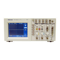
Tektronix TDS200 Series Programmer's Manual (346 pages)
Digital Oscilloscopes
Brand:
Tektronix
| Category:
Test Equipment
| Size: 1.04 MB
Table of Contents
Table of Contents
3
Preface
9
Related Documents
9
Conventions
13
Getting Started
15
Table 1- 1: Communications Ports and Functions
17
Table 1- - 2: Oscilloscope, Extension Module, and
18
Syntax and Commands
19
Command Syntax
21
Status and Events
21
Registers
21
Status Registers
21
Programming Examples
21
Appendix A: ASCII Code Chart
21
Appendix B: Factory Setup
21
TDS1000B and TDS2000B Series Oscilloscopes
21
Table 2- 1: Oscilloscope Communication Protocol
21
Command and Query Structure
22
Table 2- 2: BNF Notation
22
TPS2000 Series Oscilloscopes
23
Table 2- 3: Command Message Elements
23
Enable Registers
24
Figure 2- 1: Command Message Elements
24
TDS1000 and TDS2000 Series Oscilloscopes
25
Table 2- 4: Comparison of Header off and Header on Responses
25
Command Entry
26
The Enable Registers and the *PSC Command
26
Queues
26
The Output Queue
26
TDS210 and TDS220 Oscilloscopes
26
The Event Queue
27
Event Handling Sequence
28
TDS224 Oscilloscopes
28
Constructed Mnemonics
29
Synchronization Methods
30
Argument Types
31
Using the *WAI Command
31
Table 2- 5: Types of Numeric Arguments
31
Table 2- - 6: Oscilloscope Handling of Incorrect
32
Using the BUSY Query
33
Table 2- 7: Parts of a Block Argument
33
Using the *OPC Set Command
34
Figure 2- 2: Block Argument Example
34
Command Groups
35
Acquisition Commands
35
Table 2- 8: Acquisition Commands
35
Calibration and Diagnostic Commands
36
Using the *OPC? Query
36
Table 2- 9: Calibration and Diagnostic Commands
36
Cursor Commands
37
Messages
37
Table 2- 10: Cursor Commands
37
Display Commands
38
Table 2- 11: Display Commands
38
File System Commands (TDS2MEM Module, TDS1000B, TDS2000B, and TPS2000 Only)
39
Table 2- 12: File System Commands
39
Hard Copy Commands
40
Table 2- 13: Hard Copy Commands
40
Horizontal Commands
41
Table 2- 14: Horizontal Commands
41
Math Commands
42
Table 2- 15: Math Commands
42
Measurement Commands
43
Table 2- 16: Measurement Commands
44
Miscellaneous Commands
45
Table 2- 17: Miscellaneous Commands
45
Pictbridge Commands (TDS1000B and TDS2000B Only)
47
Table 2- 18: Pictbridge Commands
47
Power and Battery-Related Commands (TPS2000 Only)
48
Power Measurement (TPS2000 with TPS2PWR1 Power Analysis Application Key Installed Only)
48
Table 2- - 19: Power and Battery-Related Commands
48
Table 2- 20: Power Measurement Commands (TPS2000 with TPS2PWR1 Only)
49
RS-232 Commands
52
Save and Recall Commands
52
Table 2- 21: RS-232 Commands
52
Status and Error Commands
53
Trigger Commands
54
Vertical Commands
56
Waveform Commands
57
Waveform Data Formats
60
Waveform Data Record
62
Waveform Data Locations and Memory Allocation
62
Waveform Preamble
63
Scaling Waveform Data
63
Transferring Waveform Data
63
Command Descriptions
65
Figure 3- 1: the Standard Event Status Register (SESR)
288
Figure 3- 2: the Status Byte Register (SBR)
289
Figure 3- - 3: the Device Event Status Enable Register
291
Figure 3- 4: the Event Status Enable Register (ESER)
291
Figure 3- 6: Status and Event Handling Process
295
Figure 3- - 7: Command Processing Without Using
297
Figure 3- 8: Processing Sequence with Synchronization
297
Advertisement
Tektronix TDS200 Series Programmer's Manual (291 pages)
Digital oscilloscopes
Brand:
Tektronix
| Category:
Test Equipment
| Size: 2.08 MB
Table of Contents
Table of Contents
5
Preface
7
Related Documents
8
Conventions
11
Gettingstarted
13
Getting Started
13
Syntax and Commands
17
Command Syntax
19
Command and Query Structure
20
Command Entry
22
Constructed Mnemonics
24
Argument Types
25
Command Groups
29
Acquisition Commands
29
Calibration and Diagnostic Commands
29
Counter Commands (TBS1000B/EDU Models Only)
30
Cursor Commands
30
Data Logging Commands (Available Only on TBS1000B, TBS1000 and TDS2000C Series Models)
31
Display Commands
31
FFT Commands (TBS1000B/EDU Models Only)
33
File System Commands (TBS1000B/EDU, TBS1000, TDS2000C, TDS1000C-EDU, TDS2000B, TDS1000B, TDS2MEM Module, TPS2000B, and TPS2000 Only)
33
Hard Copy Commands
35
Horizontal Commands
35
Limit Test Commands (Available Only on TBS1000B, TBS1000 and TDS2000C Series Models)
36
Math Commands
38
Measurement Commands
40
Miscellaneous Commands
41
Pictbridge Commands (TBS1000B/EDU, TBS1000, TDS2000C, TDS1000C-EDU, TDS2000B, and TDS1000B Only)
42
Power and Battery-Related Commands (TPS2000B and TPS2000 Only)
43
Power Measurement (TPS2000B/TPS2000 with TPS2PWR1 Power Analysis Application Key Installed Only)
43
Commands (TDS2000, TDS1000, TDS200, TPS2000B, and TPS2000 Only)
46
Save and Recall Commands
46
Status and Error Commands
47
Trend Plot Commands (TBS1000B Models Only)
48
Trigger Commands
48
Vertical Commands
50
Waveform Commands
50
Zoom Commands (TBS1000B/EDU Models Only)
54
Command Descriptions
57
Manual Conventions
57
Status and Events
245
Queues
248
Event Handling Sequence
249
Synchronization Methods
251
Programming Examples
265
Appendices
269
Appendix A: ASCII Code Chart
269
Appendix B: Factory Setup
271
TPS2000 Series Oscilloscopes
272
TPS2000B Series Oscilloscopes
274
TDS1000 and TDS2000 Series Oscilloscopes
275
TDS210 and TDS220 Oscilloscopes
277
TDS224 Oscilloscopes
278
Appendix C: Reserved Words
281
Tektronix TDS200 Series Programmer's Manual (250 pages)
Digital Oscilloscope
Brand:
Tektronix
| Category:
Test Equipment
| Size: 0.49 MB
Table of Contents
Table of Contents
5
Preface
9
Related Documents
9
Conventions
10
Contacting Tektronix
11
Getting Started
13
Syntax and Commands
17
Command Syntax
19
Table 2-1: BNF Notation
19
Command and Query Structure
20
Table 2-2: Command Message Elements
20
Figure 2-1: Command Message Elements
21
Table 2-3: Comparison of Header off and Header on
23
Constructed Mnemonics
26
Argument Types
28
Command Entry
23
Table 2-4: Types of Numeric Arguments
28
Table 2-5: Oscilloscope Handling of Incorrect Numeric
29
Table 2-6: Parts of a Block Argument
30
Figure 2-2: Block Argument Example
31
Command Groups
33
Acquisition Commands
33
Calibration and Diagnostic Commands
33
Table 2-7: Acquisition Commands
33
Table 2-8: Calibration and Diagnostic Commands
34
Display Commands
35
Hard Copy Commands
36
Horizontal Commands
36
Math Commands
37
Measurement Commands
38
Commands
39
Miscellaneous Commands
39
Save and Recall Commands
41
Status and Error Commands
42
Trigger Commands
43
Vertical Commands
44
Waveform Commands
45
Waveform Data Formats
47
Waveform Data Record
49
Scaling Waveform Data
50
Transferring Waveform Data
50
Waveform Data Locations and Memory Allocation
50
Waveform Preamble
50
Cursor Commands
34
Command Descriptions
53
Figure 3-1: the Standard Event Status Register (SESR)
200
Figure 3-2: the Status Byte Register (SBR)
201
Figure 3-3: the Device Event Status Enable Register
203
Figure 3-4: the Event Status Enable Register (ESER)
203
Figure 3-5: the Service Request Enable Register
203
Figure 3-6: Status and Event Handling Process
207
Synchronization Methods
208
Figure 3-7: Command Processing Without Using
209
Figure 3-8: Processing Sequence with Synchronization
209
Using the *WAI Command
209
Using the BUSY Query
211
Using the *OPC Set Command
212
Using the *OPC? Query
214
Messages
215
The Event Queue
205
Event Handling Sequence
206
Programming Example
223
Appendices
227
Appendix A: ASCII Code Chart
229
Appendix B: Factory Setup
231
Glossary and Index
237
Advertisement
Tektronix TDS200 Series Operator Training Kit Manual (235 pages)
Digital Real-Time Oscilloscopes
Brand:
Tektronix
| Category:
Test Equipment
| Size: 9.38 MB
Table of Contents
General Safety Summary
7
Safety Terms and Symbols
8
Table of Contents
11
Introduction to Oscilloscopes and Probes
15
Getting to Know Oscilloscopes
16
Introduction to Oscilloscopes
16
Types of Oscilloscopes
19
Oscilloscope Terminology
26
Waveform Measurements
31
Getting to Know Probes
34
Introduction to Probes
34
Types of Voltage Probes
35
How Probes Affect Measurements
38
Summary
41
Getting Started with TDS200 Oscilloscopes
44
Setting up TDS200 Oscilloscopes and Probes
44
Introduction to TDS200 Oscilloscopes
44
Setting up a TDS200 Oscilloscope
49
Probe Compensation
59
Primary Controls
65
VERTICAL Controls
65
VERTICAL Control MENU Buttons
68
MATH MENU Controls
72
HORIZONTAL Controls
76
TRIGGER Controls
81
Menu Function Controls
88
Summary
106
Using VERTICAL Controls
107
VERTICAL Control Knobs
108
Setting up VERTICAL Controls
109
Switching the Input Coupling
111
Adding Two Waveforms
117
Subtracting Two Waveforms
120
Performing FFT Operations
124
Summary
128
Using HORIZONTAL Controls
129
HORIZONTAL Control Knobs
130
Setting up HORIZONTAL Controls
132
Setting the Delay Time for a Waveform
134
HORIZONTAL Control MENU Buttons
137
Expanding the Waveform Display
137
Summary
140
Using TRIGGER Controls
141
Trigger Holdoff Controls
142
Setting up TRIGGER Controls
143
Assigning Trigger Holdoff
146
Assigning Trigger Holdoff with an am Signal
148
TRIGGER Control MENU Buttons
153
Selecting a Trigger Type
157
Selecting the Signal Coupling for a Trigger
160
Summary
163
Using Menu Function Controls
165
ACQUIRE Menu Function Controls
166
Using the Average Acquisition Mode
167
Using the Peak Detect Acquisition Mode
171
Step Response
174
DISPLAY Menu Function Controls
179
Selecting the Display Type
179
Using Persistence
182
Using the XY Display Mode
185
CURSOR Menu Function Controls
188
Measuring the Vertical Scale
188
Measuring the Horizontal Scale
191
Measuring Pulse Width
193
Measuring Rise Time
196
MEASURE Menu Function Controls
200
Taking Automatic Measurements
200
SAVE/RECALL Menu Function Controls
203
Saving and Recalling a Setup
203
Saving and Recalling a Waveform
207
UTILITY Menu Function Controls
210
Displaying the System Status
210
Summary
213
Appendix A: Training 1 Signal Board: Signal Definitions
215
Appendix B: Glossary
223
Tektronix TDS200 Series Service Manual (120 pages)
Digital Real-Time Oscilloscope
Brand:
Tektronix
| Category:
Test Equipment
| Size: 1.64 MB
Table of Contents
Section 1
6
Table of Contents
6
Table 1-1: Specifications
15
Table 1-2: General Specifications
19
Figure 2-1: Routing the Power Cord and Security Cable
25
Figure 2-2: Installing an Extension Module
26
Table 2-1: Factory Setup Settings
30
Figure 3-1: Module-Level Block Diagram (Two Channel)
35
Figure 3-2: Module-Level Block Diagram (Four Channel)
36
Table 5-1: Required Equipment
47
Figure 5-1: Service Menu Enable Button
48
Figure 5-2: Adjustment Setups
49
Table 5-2: TDS 210 and TDS 220 Adjustment Steps
51
Table 5-3: TDS 224 Adjustment Steps
53
Preparation
57
Preventing ESD
57
Inspection and Cleaning
58
Table 6-1: Internal Inspection Check List
59
Removal and Installation Procedures
61
Section 2
63
Table 6-2: List of Procedures
63
Figure 6-1: Removing the Rear Feet
64
Rear Feet
64
Figure 6-2: Installing the Rear Feet
65
Figure 6-3: Installing a Front-Case Label
66
Front-Case Label
66
Figure 6-4: Installing a New Rear-Case Label
67
Rear-Case Label
67
Figure 6-5: Removing the Handle
68
Handle
68
Figure 6-6: Installing the Handle
69
Power Button
69
Rear Case
70
Figure 6-7: Removing and Installing the Rear Cover
71
Figure 6-8: Removing and Installing the Front Feet
72
Front Feet
72
EMI Clips
73
Figure 6-9: Removing and Installing the EMI Clips
73
Figure 6-10: Removing the Flip Stand
74
Flip Stand
74
Figure 6-11: Installing the Flip Stand
75
Figure 6-12: Line Fuse Location
76
Power Line Fuse
76
Figure 6-13: Removing the Power Supply Module
77
Power Supply Module
77
Figure 6-14: Installing the Power Supply Module
78
Front Panel Knobs
79
Figure 6-15: Removing and Installing the Internal Assembly
80
Internal Assembly
80
Figure 6-16: Installing the Copper Mesh Grounding Tube
81
Main Board Module
82
Figure 6-17: Main Board Removal
83
Display Module
84
Figure 6-18: Main Board Installation
84
Figure 6-19: Removing the Display Module
85
Figure 6-20: Installing the Display Module
86
Front Panel Module
86
Figure 6-21: Removing the Front Panel Module
87
Figure 6-22: Installing the Front Panel Module
88
Figure 6-23: Removing and Installing the Keypad
89
Keypad
89
Display Shield
91
Figure 6-24: Removing the Display Shield
91
Figure 6-25: Installing the Display Shield
92
Front Case
93
Troubleshooting
94
Figure 6-26: Measuring the Backlight Voltage
97
Table 6-3: List of Error Codes
102
Repackaging Instructions
104
Options
105
Electrical Parts List
107
Diagrams
109
Parts Ordering Information
111
Replaceable Parts
111
Table 10-1: Parts List Column Descriptions
112
Using the Replaceable Parts List
112
Table 10-2: Manufacturers Cross Index
113
Table 10-3: Replaceable Parts List
114
Figure 10-1: Exploded Diagram
118
Table 10-4: Replaceable Standard Accessories
119
Table 10-5: Replaceable Optional Accessories
119
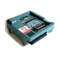
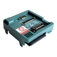
Tektronix TDS200 Series Instructions Manual (56 pages)
Extension Modules
Brand:
Tektronix
| Category:
Control Unit
| Size: 0.18 MB
Table of Contents
Table of Contents
5
General Safety Summary
6
Preface
8
Conventions
8
Command Entry
9
Contacting Tektronix
10
Getting Started
11
Dependencies
11
Features
12
Removing and Installing Modules
13
Checking Module Installation
16
Troubleshooting Module Installation
16
TDS2HM Hard Copy Module
17
Hard Copy Setup
18
Testing the Hard Copy Port
19
Printing an Oscilloscope Screen
19
TDS2CM Communications Module
20
RS-232 Setup
21
GPIB Setup
31
TDS2MM Measurement Module
37
Changed Math Operations
38
Signal Measurements
39
Using the FFT
40
Appendix A: Certifications and Compliances
52
Appendix B: Comparing GPIB and RS-232
53
Appendix C: Manuals
55
Advertisement
Related Products
Tektronix TDS2000C series
Tektronix TDS2000B Series
Tektronix TDS2000 Series
Tektronix TDS2002C
Tektronix TDS2001C
Tektronix TDS2004C
Tektronix TDS2002B
Tektronix TDS2004B
Tektronix TDS2002
Tektronix TDS2004
Tektronix Categories
Test Equipment
Measuring Instruments
Amplifier
Printer
Portable Generator
More Tektronix Manuals
Login
Sign In
OR
Sign in with Facebook
Sign in with Google
Upload manual
Upload from disk
Upload from URL