Table of Contents
Advertisement
Quick Links
Advertisement
Table of Contents

Related Manuals for Regin RDAS-24C Series


Summary of Contents for Regin RDAS-24C Series
- Page 1 WE TAKE BUILDING AUTOMATION PERSONALLY VARIABLE LIST RDAS…-24C...
- Page 2 Our goal is to make real estates in the world more energy efficient. Regin is an international group and our products sells in over 90 countries. Thanks to our global presence with strong local representation, we are well aware of the requirements of the market, as well as of how our products and systems function under the most variable conditions.
-
Page 3: Table Of Contents
Table of Contents 1 RDAS…-24C and Modbus communication .................5 Introduction ........................5 Models without spring return ....................5 Models with spring return ....................5 2 Comissioning notes........................6 General checks ........................6 2.1.1 Environmental conditions ..................6 2.1.2 Mechanical check (RDAS5-24C, RDAS10-24C, RDAS20-24C and RDAS35- 24C)........................6 2.1.3 Mechanical check (RDAS7S-24C and RDAS18S-24C) ..........6 2.1.4... -
Page 5: Rdas
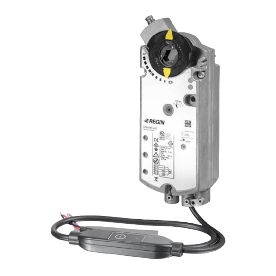
RDAS…-24C is a range of damper actuators with Modbus communication. The damper actuators are intended to use in ventilation and air conditioning sites to operate air dampers and air throttles. The actuators can be part of a complete ventilation solution, together with other products in the Regin ventilation family. -
Page 6: Comissioning Notes
Comissioning notes Comissioning notes All information necessary for commissioning is available in this document. It is available for download from Regin’s website, www.regincontrols.com 2.1 General checks 2.1.1 Environmental conditions Check to ensure that all permissible values are observed. 2.1.2 Mechanical check (RDAS5-24C, RDAS10-24C, RDAS20-24C and RDAS35-... - Page 7 Comissioning notes Figure 2-1 Clockwise RDAS…-24C variable list, Rev. A...
-
Page 8: Modbus
Modbus Modbus 3.1 HMI - Human machine interface (RDAS5-24C and RDAS10- 24C) Figure 3-1 HMI - Human machine interface (RDAS5-24C and RDAS10-24C) A = Push button, B = LED 3.1.1 Push button operation Activity Push button operation Confirmation Display current address (in reverse order) Press and hold the button for shorter than Current address is displayed, see 3.3.1 1 second... -
Page 9: Reset By Push Button
Modbus Orange 1 second on / 5 seconds off Mechanical fault / Internal error Steady Mechanical fault / Device jammed 1 second on / 5 seconds off Internal error 0.1 second on / 1 second off Bus-parameters not configured 3.1.3 Reset by push button The damper actuator can be reset by push-button: 1. -
Page 10: Led Colors And Patters
Modbus Turn bus termination on / off: turn on 1. press the button 3 times LED flashing and flickering stops (termina- tion mode) 2. press the button 1 time shortly LED flashes blue 1 time 3. press the button until LED shines red LED shines red (confirmation) 4. -
Page 11: Display Current Address (Starting With Lowest Address Digit)
Modbus 3.3.1 Display current address (starting with lowest address digit) Colours Digits 1-digits Green 10-digits Orange 100-digits Example for address 124: N N o o t t e e ! ! The address is entered and shown starting with lowest address digit, see figure above (124 in the example is starting with 4x red) 3.3.2 Set new address (starting with lowest address digit) -
Page 12: Commissioning
Modbus Figure 3-3 Example address 124 Set address "50" 1. Enter addressing mode: and hold the button for longer than 1 second until LED shines red, then release button (before LED gets dark). 2. Skip 1-digits: Hold button pressed until LED shines green - release button 3. - Page 13 Modbus Full configuration over bus. If the address is unique per segment when powered up, the device can be ✓ accessed by the Modbus master (or programming tool) and the address and other parameters can then be set to the definitive values. Partial configuration over bus: If the address is not unique per segment when powered up, each device ✓...
-
Page 14: Variable List
Variable list Variable list 4.1 Modbus registers Reg. Name Unit Scaling Range / enumeration Process Values Setpoint 0.01 0…100 Override control 0 = Off / 1= Open / 2 = Close 3 = Stop / 4 = GoToMin / 5 = GoToMax Actual position 0.01 0…100... -
Page 15: Register 769 "Status
Variable list 1409 ASN [Char_16…15] Each register: Two Example: bytes, each coding 0x47 44 = GD 1410 ASN [Char_14…13] an ASCII char. 0x42 31 = B1 ASN is coded 0x38 31 = 81 1411 ASN [Char_12…11] beginning with reg. 0x2E 31 = .1 1412 ASN [Char_10…9] 1409... - Page 16 Variable list Backup mode 513, ✓ In case the communication to the controller is lost, the device can be configured to go into a defined state. 514, ✓ Default setting mode is "keep last setpoint", i.e. in case of communication loss, the device controls to the last received setpoint.
- Page 17 RDAS…-24C variable list, Rev. A...
- Page 18 HEAD OFFICE AB Regin, Box 116, SE-428 22 Kållered • Visiting address: Bangårdsvägen 35, SE-428 36 Kållered Phone: +46 (0)31 720 02 00 • Fax: +46 (0)31 720 02 50 • info@regincontrols.com • www.regincontrols.com...
Need help?
Do you have a question about the RDAS-24C Series and is the answer not in the manual?
Questions and answers