Advertisement
Notice to Installer: Instructions must remain with installation.
Product information presented
here refl ects conditions at time
of publication. Consult factory
regarding discrepancies or
inconsistencies.
PREINSTALLATION CHECKLIST - ALL INSTALLATIONS
1. Inspect all materials. Occasionally, products are damaged during shipment. If the unit is damaged, contact your dealer before using.
2. Carefully read all the literature provided to familiarize yourself with specifi c details regarding installation and use before attempting the
installation. These materials should be retained for future reference.
1 .
To help reduce the risk of electrical shock, a proper ground
or control box of grounding type must be installed and protected
by a ground fault circuit interrupter (GFCI) in accordance with the
National Electrical Code and applicable local codes.
2.
DO NOT USE AN EXTENSION CORD. Extension cords that are
too long or too light do not deliver suffi cient voltage to the pump
motor. But more important, they could present a safety hazard if
the insulation were to become damaged or the connection end were to fall
into a damp or wet area.
3. Make sure the pump's electrical supply circuit is equipped with fuses
or circuit breakers of proper capacity. A separate branch circuit, sized
according to the National Electrical Code for the current shown on the pump
name plate is recommended.
4.
TESTING FOR GROUND. As a safety measure, electrical supply
should be checked for ground using an Underwriters Laboratory
Listed circuit analyzer which will indicate if the power, neutral and
ground wires are correctly connected . If they are not, call a qualifi ed licensed
electrician.
5.
Installation and checking of electrical circuits and hardware should
only be performed by a qualifi ed licensed
electrician.
6.
FOR YOUR PROTECTION ALWAYS DISCONNECT PUMP FROM
ITS POWER SOURCE BEFORE HANDLING. De-energize the
circuit at the control box. If the power point is out-of-sight, lock it
in the open position and tag it to prevent unexpected application of power.
Failure to do so could result in fatal electrical shock.
1. Check to be sure your power source is adequate to handle the
amperage requirements of the motor as indicated on the pump or
unit I.D. tag.
2. All plumbing (discharge and intake lines) must be installed to
meet local codes.
MAIL TO: P.O. BOX 16347 • Louisville, KY 40256-0347
SHIP TO: 3649 Cane Run Road • Louisville, KY 40211-1961
(502) 778-2731 • 1 (800) 928-PUMP • FAX (502) 774-3624
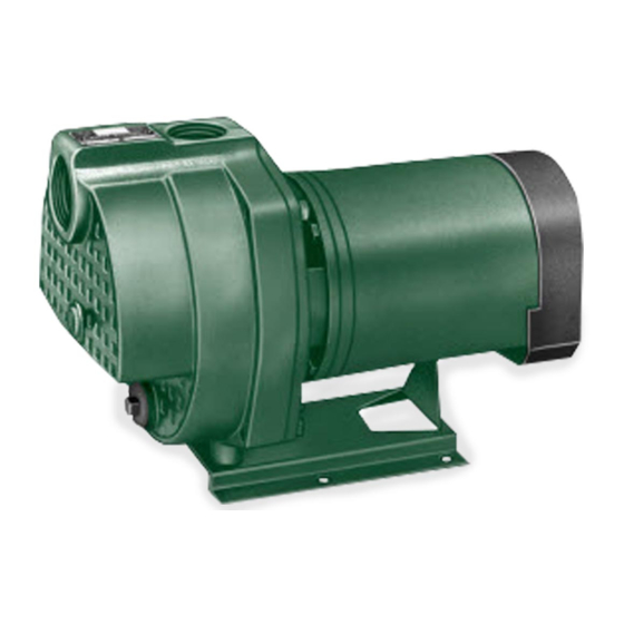
INSTALLATION INSTRUCTIONS
330 Series Centrifugal, Lawn Sprinkler Pumps
SEE BELOW FOR LIST OF WARNINGS
SEE BELOW FOR LIST OF CAUTIONS
© Copyright 2003 Zoeller Co. All rights reserved.
7.
Unit must be securely and adequately electrically grounded. This can be
accomplished by wiring the unit to a ground metal-clad raceway system or
by using a separate ground wire connected to the bare metal of the motor
frame or other suitable means.
8.
Do not put a valve in the discharge line without automatic shut-off
capability. Failure to install an automatic shut-off (pressure switch
and tank) can allow the pump to run at no fl ow causing the pumped
liquid to overheat and cause steam burns.
9.
Risk of electric shock. This pump has not been investigated for
use in swimming pool areas.
10. According to the state of California (Prop 65), this product contains chemicals
known to the state of California to cause cancer and birth defects or other
reproductive harm.
NOTE: Repair and service should be performed by an Authorized Service Station
only (Consult factory).
NOTE: Pumps are designed to have a maximum static lift (suction head) of 25
feet (vertical distance from water surface to center line of pump).
NOTE: Pumps with the CSA CUS mark are tested to UL standard UL 778 and
certifi ed to CSA standard C22.2 No. 108.
3. Be certain the pump is completely primed before starting. Otherwise
damage may occur to the seal.
4.
Be careful when touching the exterior of an operating
motor - it may be hot enough to be painful or cause
injury.
1
SECTION: 6.10.049
FM2101
Supersedes
visit our web site:
http://www.zoeller.com
020293
0703
0603
Advertisement
Table of Contents

Subscribe to Our Youtube Channel
Related Manuals for Zoeller 330 Series


Summary of Contents for Zoeller 330 Series
- Page 1 Be careful when touching the exterior of an operating 2. All plumbing (discharge and intake lines) must be installed to motor - it may be hot enough to be painful or cause 020293 meet local codes. injury. © Copyright 2003 Zoeller Co. All rights reserved.
-
Page 2: Limited Warranty
Zoeller Pump Company warrants, to the purchaser and subsequent owner This warranty is in lieu of all other warranties expressed or implied; and during the warranty period, every new Zoeller Pump Company product to we do not authorize any representative or other person to assume for be free from defects in material and workmanship under normal use and us any other liability in connection with our products. -
Page 3: Pump Performance
1 — Suction Pipe 2 — Discharge Pipe 3 — Elbow 4 — Gate Valve 5 — Union 6 — Discharge Tee 7 — Priming Plug 8 — Pump 9 — Fuse Box © Copyright 2003 Zoeller Co. All rights reserved. - Page 4 Figure 7. Make sure con- nections are correct for the voltage being supplied to the motor. © Copyright 2003 Zoeller Co. All rights reserved.
- Page 5 Freezing Drain the entire system if there is danger of freezing. A drain plug is provided at the bottom of the pump case for this purpose. © Copyright 2003 Zoeller Co. All rights reserved.
- Page 6 © Copyright 2003 Zoeller Co. All rights reserved.
- Page 7 020291 Hex Hd. Cap Screws 7/16 x 1” Base 134217 Hex Hd. Cap Screws 3/8 x 1/2” (*) Standard Hardware Item (▲) Not Shown SELF-PRIMER PUMP REPAIR PARTS — 330 SERIES IL0174 © Copyright 2003 Zoeller Co. All rights reserved.
-
Page 8: Troubleshooting Chart
6. Thermal overload has opened circuit 6. Allow unit to cool, restart after reason for for overload has been determined Pumps leaks at shaft 1. Worn mechanical seal 1. Replace (see Rotary Seal Replacement) © Copyright 2003 Zoeller Co. All rights reserved.
Need help?
Do you have a question about the 330 Series and is the answer not in the manual?
Questions and answers