Table of Contents
Advertisement
Quick Links
INSTRUCTION
MANUAL
Gas Detector
DEGA NSx-yL III LCD
Reproduction of this manual, or any part thereof, in any form, without the prior permission of DEGA.CZ s.r.o. is
prohibited
DEGA CZ s.r.o. reserves the right to alter the specifications of the hardware and software described in this
manual at any time and without prior notice
DEGA CZ s.r.o. bears no liable for any damage resulting from use of this device
Advertisement
Table of Contents

Related Manuals for DEGA NSx-yL III LCD


Summary of Contents for DEGA NSx-yL III LCD
- Page 1 Gas Detector DEGA NSx-yL III LCD Reproduction of this manual, or any part thereof, in any form, without the prior permission of DEGA.CZ s.r.o. is prohibited DEGA CZ s.r.o. reserves the right to alter the specifications of the hardware and software described in this manual at any time and without prior notice DEGA CZ s.r.o.
-
Page 2: Table Of Contents
Replacement of the sensor module ............................6 Replacement of the battery ..............................6 Connecting the detector via current loop to the controler DEGA UPA II/DEGA UPA III ............7 Connecting the sensor via RS485 to the controller DEGA UKAIII/DEGA UPA III/DEGA UDA III ..........7 Installation of wiring for RS485 ............................. -
Page 3: For Your Safety
Use the detector only with the appropriate certified DEGA products The device is certified as functionally and technically qualified only with original "DEGA" accessories. In case of using the device with any other products the manufacturer is not liable for any damages that may occur. -
Page 4: Operational Conditions
Flow of ambient air: max. 2 m/s - flow directly to the sensor in not allowed Protection level with a cover: IP 54, with a DEGA WATER CAP IP 66 cover Location: BE3N2 - explosive atmoshpheres - zone 1 (2 G) -
Page 5: Product Description
Their disadvatage is their low selectivity - the sensor largly responds to other gases for which it is not calibrated. DEGA NSx-PL III LCD PID with a PID – photoionization sensor Typical photoionization detectors measure volatile organic compounds and other gases in concentrations from sub parts per billion to 10 000 parts per million (ppm). -
Page 6: Instalation, Assembly And Disassembly Of The Detector
ERROR Jumper connector of Jumper connector of the Expanding contact Expanding contact relay the terminal resistor communication protocol relay 2 RS485 (DEGA/MODBUS) DIP switch for the RS485 Programming Battery CR2032 LCD display connector adress connector Status LED Calibration jumpers... -
Page 7: Connecting The Detector Via Current Loop To The Controler Dega Upa Ii/Dega Upa Iii
4. Connecting the detector via current loop to the controler DEGA UPA II/DEGA UPA III Connect one detector to each channel of the controler as shown in the picture below 5. Connecting the sensor via RS485 to the controller DEGA UKAIII/DEGA UPA III/DEGA UDA III 6. -
Page 8: Communication Protocol Switch Dega/Modbus
9. Communication protocol switch DEGA/MODBUS Plugging a jumper in the JP1 connector will swtich from the DEGA communication protocol to the MODBUS communication protocol. Detector functions The detector's motherboard is equipped by status LEDs, which help in detecting problems during the installation. -
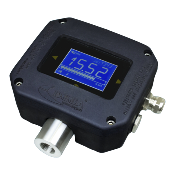
Page 9: Detector Controls
Detector controls Detectors equipped with an LCD display can be controlled by the magnetic contact located on the sides of the display Warning: calibration Warning: Service is required required Data display Time display Channel number Activated magnetic (adress) control Communication with the Calibration icon control panel in progress... -
Page 10: History Menu „Hist
Settings Detector configuration Test Testing the detector funcions Exit Return to normal operation 1. History menu „HIST“ Browsing the history Menu Display Description History of all Use „ “ to go trough individual alarms. Displays the alarms date and time of the alarm. Return to the history menu „... -
Page 11: Settings Menu „Set
Date of last Displays the date of the last calibration calibration Power voltage Displays the power voltage Temperature Displays the chip temperature (about 15°C higher than the ambient temperature) RS485 device Displays the device adress adress Range up to Measured concentration value corresponding to 20 mA current Alarm level 1 Displays alarm level 1... - Page 12 Changing the password Changing the password Setting the year Setting the year Setting the date Setting the date Setting the time Setting the time Exit Calibration a) Connect fresh air to the sensor input. The icon flashes After the value stabilizes, move onto the next step using „...
-
Page 13: Test Menu „Test
e) Using „ “ switch between „YES“ - save settings, nebo „NO“ - return to the Settings menu. Confirm the selected option „ “ Setting the year a) Using „ “ select a number in thousands. Save the selected number „ “... -
Page 14: Operation, Maintenance, Inspection And Service Of The Detector
We recommend using gas intended for laboratory use For the „functional control“ do not use means for testing fire alarm detectors! Perform calibration only at certified service centers with a valid certificate of competence or the manufacturer. For the Czech Republic only DEGA CZ s.r.o. -
Page 15: Accessories And Basic Types Of Detectors
Accessories and basic types of detectors 1. Calibration adapter/connection to the gas pump DEGA GAS INLET 2. Cover against splashing water DEGA WATER CAP 3. Funnel for gas collection DEGA COLLECT CAP 4. Additional Ex „d“ cable gland M20x1,5 Basic type of detectors 1. - Page 16 Carbon Carbon Monoxide 40100109 DEGA NSCO-EL A500 III LCD 0- A500 ppm 0-500 ppm 1 ppm Monoxide (CO) 130 ppm Carbon 0-2000 ppm Carbon Monoxide 40100110 DEGA NSCO-EL 2000 III LCD 0–2000 ppm 1 ppm Monoxide (CO) 130 ppm Ammonia...
-
Page 17: Detectors With An Infrared Sensor Nsx-Il Iii Lcd
3. Detectors with an infrared sensor NSx-IL III LCD Measurement of Measurement Product code Detector type Detected gas current loop Resolution Calibration gas range (4-20mA) Carbon dioxide 40100164 DEGA NSCO2-IL 5 III LCD RE 0-5 % vol. 0-2,5 % vol. 0,1 % Oxid uhličitý 2,5 % vol. (CO2) -
Page 18: Detectors With A Semiconductor Sensor Nsx-Sl Iii Lcd
Methane (CH 40100165 DEGA NSM-IL 100 III LCD RE Natural gas 0–100 % LEL 0-20 % LEL 0,1 % Metan 0,88 % LEL Butan / LPG 40100166 DEGA NSP-IL 100 III LCD RE 0–100 % LEL 0-20 % LEL 0,1 %... -
Page 19: Add-On Modules
Add-on modules Product code Name Product description 40200003 DEGA NS III Relay Modul Internal 4-relay, 250 V/10 A 40200010 DEGA NS III RS485 Internal output RS485 40200011 DEGA NS III Buzzer Internal buzzer on PCB, 4 VDC, 7 VDC, 30 mA, 88 dB Attachments 1. -
Page 20: Signalization Transmitted By The Current Loop 4-20 Ma
enter measurement mode Reserved reserved Error reading the internal Restart the detector. If the FLASH error persists, contact the manufacturer Error reading the internal Restart the detector. If the FLASH error persists, contact the manufacturer Error reading the internal Restart the detector. If the FLASH error persists, contact the manufacturer... -
Page 21: General Warranty Terms And Conditions
• DEGA products that have been used in association with other than original DEGA products, including consumables and accessories •...
Need help?
Do you have a question about the NSx-yL III LCD and is the answer not in the manual?
Questions and answers