Table of Contents
Advertisement
Quick Links
INSTRUCTION
MANUAL
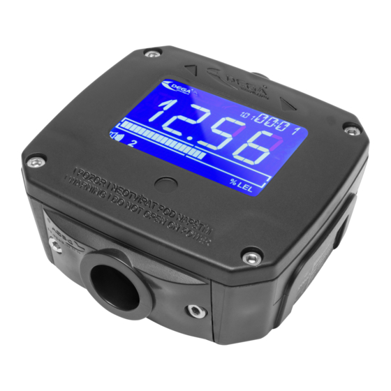
Gas detector
DEGA NB III LCD
Reproduction of this manual or any part thereof, in any form, without the prior permission of DEGA.CZ s.r.o. is
prohibited
DEGA CZ s.r.o. reserves the right to alter the specifications of the hardware and software described in this manual at
any time and without prior notice
DEGA CZ s.r.o. bears no liability for any damage resulting from use of this device
Advertisement
Table of Contents

Related Manuals for DEGA NB III LCD


Summary of Contents for DEGA NB III LCD
- Page 1 Reproduction of this manual or any part thereof, in any form, without the prior permission of DEGA.CZ s.r.o. is prohibited DEGA CZ s.r.o. reserves the right to alter the specifications of the hardware and software described in this manual at any time and without prior notice...
-
Page 2: Table Of Contents
Operation .................................... 12 Operation/Maintenance ..............................12 Accessories ...................................... 12 1. Additional bushing DEGA BUSHING for NBx III ........................12 Basic type of detectors ................................... 12 Detectors with a catalytic sensor NBx-CL III LCD ........................ 12 Detectors with an electrochemical sensor NBx-EL III LCD ....................13 Detectors with an infrared sensor NBx-IL III LCD ........................ -
Page 3: Technical Data And Information
The detector is intended for use exclusively in a non-explosive environment Detectors DEGA NSx-yL II (ZONE 2) and NSx-yL III (ZONE 1) are designed for use in potentially explosive environment. Do not disassemble the product and ensure against the contact of its internal components with water Contact of internal components of the product with water may cause an electric shock. -
Page 4: Operational And Storage Conditions
These sensors have good selectivity and the ability to detect very low concentrations of toxic gases. DEGA NBx-CL III LCD with a catalytic sensor (Pelistor) They operate on the principle of catalytic combustion - gas concentration is measured based on the amount of heat released in a controlled combustion reaction. -
Page 5: Installation, Assembly And Disassembly Of The Detector
Allen screws 3mm Magnetic control Magnetic control Bushings „BACK“ „FRONT“ Magnetic control PCB with Sensor module PCB with electronics „ENTER/EXIT“ electronics Power supply Power supply terminal Relay outputs Connector for service terminal block 230V block230V - N terminal block operations Installation, assembly and disassembly of the detector Before assembling, read the valid installation standards ČSN EN 60079-29-2 (Selection, installation, use and maintenance of detectors for combustible gases and oxygen) and ČSN EN 45544-4 (Guidelines for the selection, installation, use and... -
Page 6: Connecting The Detector - 230V Ac
3. Connecting the detector - 230V AC 4. Connecting the detector - 24V. Only for version NBx-yL III LCD RE 24V. Detector functions 1. Turning on the detector When the detector power is switched on, automatic test procedures begin, which can take up to 180 seconds, depending on the sensor used. -
Page 7: Detector Controls
Detector control The detector equipped with an LCD display can be controlled by the magnetic contact located on the sides of the display. Warning: calibration Warning: Service is required required Data display Time display Activated magnetic Channel number (address) control Communication with the Calibration icon control panel in... -
Page 8: Menu History „Hist
Testing the detector functions Test Return to normal operation Exit 6. Menu History „HIST“ Browsing the history Menu Display Description History of all Use „ “ to go trough individual alarms. Displays the alarms date and time of the alarm. Return to the history menu „... -
Page 9: Settings Menu „Set
Displays the power voltage Power voltage Displays the chip temperature (about 15°C higher than Temperature the ambient temperature) Displays the device address RS485 device address Displays alarm level 1 Alarm level 1 Displays alarm level 2 Alarm level 2 Displays alarm level 3 Alarm level 3 Displays alarm level 4 Alarm level 4... - Page 10 Setting the time Setting the time Return to the main menu Exit Calibration a) Connect fresh air to the sensor input. The icon flashes After the value stabilizes, move onto the next step using „ “ „ “ b) Using „ “...
-
Page 11: Menu Test „Test
Setting the date a) Using „ “ select a number in thousands. Save the selected number „ “ b) Using „ “ select a number in hundreds. Save the selected number „ “ c) Using „ “ select a number in tens. Save the selected number „ “... -
Page 12: Operation
Perform calibration only at certified service centers with a valid certificate of competence or at the manufacturer. For the Czech Republic only DEGA CZ s.r.o. Accessories 1. Additional bushing DEGA BUSHING for NBx III Basic type of detectors 1. -
Page 13: Detectors With An Electrochemical Sensor Nbx-El Iii Lcd
Product code Detector type Detected gas current loop Resolution Calibration gas range (4-20 mA) Carbon Carbon Monoxide DEGA NBCO-EL 1000 III LCD 0–1000 ppm 0-130 ppm 1 ppm 20100122 Monoxide (CO) 450 ppm Carbon Carbon Monoxide DEGA NBCO-EL 200 III LCD 0–200 ppm... - Page 14 DEGA NBSO2-EL 200 III 0-200 ppm 0-200 ppm 0,1 ppm Sulfur dioxide 50 ppm 20100165 Sulfur dioxide DEGA NBSO2-EL 2000 III LCD 0-2000 ppm 0-2000 ppm 1 ppm Sulfur dioxide 1000 ppm 20100166 Sulfur dioxide DEGA NBSO2-EL 100 III LCD...
-
Page 15: Detectors With An Infrared Sensor Nbx-Il Iii Lcd
Detector type Detected gas current loop Resolution Calibration gas range (4-20 mA) Carbon dioxide Carbon dioxide DEGA NBCO2-IL 5 III LCD 0-5 % vol. 0-2,5 % vol. 0,1 % 20100175 (CO2) 2,5 % vol. Carbon dioxide Carbon dioxide DEGA NBCO2-IL HC III LCD 0-100 % vol. -
Page 16: Add-On Modules
Add-on modules Product code Name Product description 20200004 DEGA NB III Relay Modul Internal 2-relay, 250 V/10 A Attachments Table of error codes code cause solution Sensor is not present (EEPROM is not Disconnect and reconnect the sensor, communicating) then restart the sensor by disconnecting... -
Page 17: General Warranty Terms And Conditions
• DEGA products that have been used in association with other than original DEGA products, including consumables and accessories •...
Need help?
Do you have a question about the NB III LCD and is the answer not in the manual?
Questions and answers