DEGA NS III Instruction Manual
Gas transmitter
Hide thumbs
Also See for NS III:
- Instruction manual (21 pages) ,
- Instruction manual (15 pages) ,
- Instruction manual (19 pages)
Table of Contents
Advertisement
Quick Links
INSTRUCTION
MANUAL
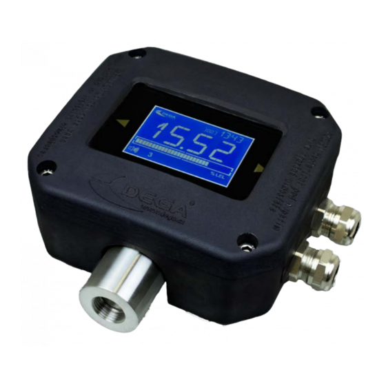
Gas Transmitter
DEGA NS III
Reproduction of this manual, or any part thereof, in any form, without the prior permission of
DEGA.CZ s.r.o. is prohibited.
DEGA CZ s.r.o. reserves the right to alter the specifications of the hardware and software
described in this manual at any time and without prior notice.
DEGA CZ s.r.o. bears no liable for any damage resulting from use of this device.
Advertisement
Table of Contents

Related Manuals for DEGA NS III


Summary of Contents for DEGA NS III
- Page 1 Reproduction of this manual, or any part thereof, in any form, without the prior permission of DEGA.CZ s.r.o. is prohibited. DEGA CZ s.r.o. reserves the right to alter the specifications of the hardware and software described in this manual at any time and without prior notice.
-
Page 2: Table Of Contents
Replacement of the battery ..............................6 Connecting the transmitter via current loop to the controler DEGA UPA II DEGA UPA III a DEGA UDA III ......6 Connecting the sensor via RS485 to the controller DEGA UPA III/UDA III ................7 Installation of wiring for RS485 ............................. -
Page 3: For Your Safety
Use the transmitter only with the appropriate certified DEGA products The device is certified as functionally and technically qualified only with original "DEGA" accessories. In case of using the device with any other products the manufacturer is not liable for any damages that may occur. -
Page 4: Operational Conditions
Consumption/input at 24V (output 4-20mA) Time to stabilize (>5day without power) DEGA NSx-EL III 45 mA/1,1 W DEGA NSx-EL II LCD RE Up to several hours - based on sensor type DEGA NSx-CL III 90 mA/2,2 W DEGA NSx-CL II LCD RE max. 1 h... -
Page 5: Product Desciption
Other types: DEGA NSx-yL III LCD - with an LCD display DEGA NSx-yL III LCD RE - with an LCD display and a quad relay DegaConfig - sensor adjusting software enabling it's full configuration and calibration. Product desciption Ex „d“... -
Page 6: Instalation, Assembly And Disassembly Of The Transmitter
4. Connecting the transmitter via current loop to the controler DEGA UPA II DEGA UPA III a DEGA UDA III Connect one transmitter to each channel of the controler as shown in the picture below... -
Page 7: Connecting The Sensor Via Rs485 To The Controller Dega Upa Iii/Uda Iii
5. Connecting the sensor via RS485 to the controller DEGA UPA III/UDA III 6. Installation of wiring for RS485 Wiring must be done using bus topology and according to the RS485 principles. Maximum number of connected transmitters per controler channel is 16 (may be less depending on the configuration of the controller), while the total length of the connecting cable (electrical distance between the controller and the last transmitter) should not exceed 1200 meters. -
Page 8: Communication Protocol Switch Dega/Modbus
2. Gas detection The transmitter continuously measures the detected gas concentration in the atmoshpere and converts it's current value into a 4-20 mA signal or transmits it's value to the evaluation unit via DEGA/MOBUS protocol. 3. Malfunction If a malfunction of electronics or the sensor is detected during operation, the transmitters starts transmitting via a 0,5mA current loop. -
Page 9: Operation
Perform calibration only at certified service centers with a valid certificate of competence or the manufacturer. For the Czech Republic only DEGA CZ s.r.o. Accessories and basic types of transmitters 1. Calibration adapter/connection to the gas pump DEGA GAS INLET... -
Page 10: Cover Against Splashing Water Dega Water Cap
2. Cover against splashing water DEGA WATER CAP 3. Funnel for gas collection DEGA COLLECT CAP 4. Additional Ex „d“ bushing DEGA VÝVODKApro NSxIII M20x1,5 Basic types of transmitters 1. Transmitters with a catalytic sensor NSx-CL III Measurement of Measurement... - Page 11 Ammonia 0-500 ppm 1 ppm Ammonia DEGA NSA-EL 500 III 0-500 ppm 100 ppm 40100040 Ammonia 0-5000 ppm 1 ppm Ammonia 40100043 DEGA NSA-EL 5000 III 0-5000 ppm 100 ppm Ammonia 0-2000 ppm 1 ppm Ammonia 40100042 DEGA NSA-EL 2000 III...
-
Page 12: Transmitters With An Infrared Sensor Nsx-Il Iii
Ethylene oxide 40100011 DEGA NSC2H4O-EL 10 III 0–10 ppm 0-1,5 ppm 0,01 ppm Ethylene oxide 2 ppm Ethylene oxide 40100012 DEGA NSC2H4O-EL 100 III 0–100 ppm 0-100 ppm 0,1 ppm Ethylene oxide 100 ppm Ethylene oxide 40100013 DEGA NSC2H4O-EL 1000 III 0–1000 ppm... -
Page 13: Transmitters With A Semiconductor Sensor Nsx-Sl Iii
Hexane 40100087 DEGA NSC6H14-IL 100 III 0–100 % 0-20 % 0,1 % Hexane 20 % (Petrol) Nitrous oxide 40100088 DEGA NSN2O-IL 1 III 0-1 % LEL 0-0,5 % LEL 0,01 % Nitrous oxide 0,5 % LEL Pentane 40100086 DEGA NSC5H12-IL 100 III 0–100 %... -
Page 14: General Warranty Terms And Conditions
DEGA products that have been used in association with other than original DEGA products, including consumables and •...
Need help?
Do you have a question about the NS III and is the answer not in the manual?
Questions and answers