
Subscribe to Our Youtube Channel
Related Manuals for ASROCK 2U4G Series


Summary of Contents for ASROCK 2U4G Series
- Page 1 2U4G Series User Manual Version 1.0 Published March 2019 Copyright©2019 All rights reserved.
- Page 2 Version 1.0 Published December 2020 Copyright©2020 All rights reserved. Copyright Notice: No part of this documentation may be reproduced, transcribed, transmitted, or translated in any language, in any form or by any means, except duplication of documentation by the purchaser for backup purpose, without written consent of us. Products and corporate names appearing in this documentation may or may not be registered trademarks or copyrights of their respective companies, and are used only for identification or explanation and to the owners’...
- Page 3 Setting up the Server in a Restricted Access Location • Access can only be gained by service persons or by users who have been instructed about the reasons for the restrictions applied to the location and about any precautions that shall be taken. • Access is through the use of a tool or lock and key, or other means of security, and is controlled by the authority responsible for the location.
-
Page 4: Table Of Contents
Contents Chapter 1 Introduction Shipping Box Contents Specifications Chapter 2 Server System Overview System Components Internal Features System Front Panel System Rear Panel Front Control Panel Buttons and LEDs PSU LED Drive Tray LEDs Chapter 3 Hardware Installation and Maintenance Server Top Cover Hard Drive Power Supply... - Page 5 Appendix A Installing the CPU (Socket: LGA-3647) Installing the CPU (Socket: LGA-4094) Appendix B Jumper Settings for the Riser Board Appendix C Block Diagram: EPYCD8 (for 2U4G-EPYC) Block Diagram: EP2C621D12 WS (for 2U4G-C621WS) Block Diagram: ROMED8QM-2T (2U4G-ROME/2T)
-
Page 6: Chapter 1 Introduction
2U4G Series Chapter 1 Introduction Thank you for purchasing 2U4G Series, a reliable system produced under our consistently stringent quality control. It delivers excellent performance with robust design conforming to our commitment to quality and endurance. Because the hardware specifications might be updated, the content of this documentation will be subject to change without notice. -
Page 7: Shipping Box Contents
1.1 Shipping Box Contents Item Quantity GPU Power Cable (Red & Orange / L=800mm ; Blue & Green / L=500mm) PMBus Cable (L=390mm) Power ATX Cable (8PIN) (L=350mm) Power ATX Cable (24 PIN TO 24 PIN ) (L=150mm) SWB Power Cable (SWB CABLE 2*6P(3.0)PWR; L=400mm) HDD Power Cable (HDD PWR 2*4P TO 2*6P;... -
Page 8: Specifications
2U4G Series 1.2 Specifications 2U4G Series (2U4G-EPYC / 2U4G-C621WS / 2U4G-ROME/2T) System Physical Status Form Factor 2U Rackmount Dimension 438x 795x 87.5 mm (without ear) (D x W x H) Support MB Size EATX 12" x 13" (EP2C621D12 WS) / ATX 12 " x 9.6" (EPYCD8) / ATX 12 "... -
Page 9: Chapter 2 Server System Overview
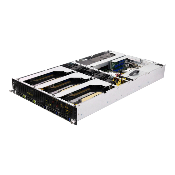
Chapter 2 Server System Overview This chapter provides diagrams showing the location of important components of the server system. 2.1 System Components 2 x Power Supply Units Sever Board (2U4G-C621WS only) 1 x Riser Card Assemby (LAN Card) 6 x System Fans 1 x PCIE Card Slot (2U4G-C621WS only: Retimer Card PE-SSD-RT... -
Page 10: Internal Features
2U4G Series 2.2 Internal Features Item / per node Item / per node Server Board System Fan4 (The serverboard varies depending on the System Fan5 system SKU.) System Fan6 PCIE Card Slot (for Retimer Card Switch Board (2U4G-C621WS / 2U4G-... -
Page 11: System Front Panel
2.3 System Front Panel Description Control Panel Buttons and LEDs Front Vent 2.5" HDD Tray (NVME0) 2.5" HDD Tray (NVME1 / HDD1) 2.5" HDD Tray (HDD2) 2.5" HDD Tray (HDD3) 2.5" HDD Tray (HDD4) To enable NVME SSD for 2U4G-C621WS system, please install the Retimer Card (PE- SSD-RT) on the rear I/O (refer to Chapter 3.8 Installing a PCIE Card) and connect the the Retimer Card to the motherboard via the Retimer Card cables. -
Page 12: System Rear Panel
2U4G Series 2.4 System Rear Panel 2U4G-EPYC Redundant PSU 1+1: Only one PSU is allowed to be removed while the server is running. Description 2 x Power Supply Units (Redundant PSU 1+1) *Server requires 1 working PSU, with 1 redundant PSU. You must have at least one active supply, installed, functioning and connected to AC. - Page 13 2U4G-ROME/2T Redundant PSU 1+1: Only one PSU is allowed to be removed while the server is running. Description 2 x Power Supply Units (Redundant PSU 1+1) *Server requires 1 working PSU, with 1 redundant PSU. You must have at least one active supply, installed, functioning and connected to AC.
-
Page 14: Front Control Panel Buttons And Leds
2U4G Series 2.5 Front Control Panel Buttons and LEDs Front Control Panel Description LAN2 Activity LED LAN1 Activity LED System Event LED 2 x USB 2.0 Ports Power Button and LED UID LED Power Button Press the power switch button to toggle the system power on and off modes. -
Page 15: Psu Led
LAN1, LAN2 LEDs Status Description Green Link between system and network or no access Blinking Green Network access System Event LED Status Description Running or normal operation At least one sensor has critical alert 2.6 PSU LED PSU LED PSU LED PSU Status LED Status Description... -
Page 16: Drive Tray Leds
2U4G Series 2.7 Drive Tray LEDs Description HDD ACT LED HDD STATUS LED Status LED Definitions HDD ACT LED Status Description Solid Green HDD active Blinking Green HDD accessing or reading No HDD HDD STATUS LED Status Description Normal HDD failed... -
Page 17: Chapter 3 Hardware Installation And Maintenance
Chapter 3 Hardware Installation and Maintenance This chapter helps you assemble the chassis and install components. Before You Begin Before you work with the server, pay close attention to the “Important Safety Instructions” at the beginning of this manual. 1. Make sure the server is powered off. Power down the server if it is still running. -
Page 18: Server Top Cover
2U4G Series 3.1 Server Top Cover Removing the Server Top Cover 1. Before removing the top covers, power off the server and unplug the power cord. 2. The system must be operated with all the chassis top covers installed to ensure proper cooling. - Page 19 3. Release the thumbscrews that secure the top front cover to the chassis. 4. Push the top front cover toward the FRONT of the chassis to remove the cover from the locked position. Lift up and remove the top front cover.
- Page 20 2U4G Series Installing the Server Top Cover 1. Lower the top front cover on the chassis, making sure the side latches align with the cutouts. Slide the top front cover toward the REAR of the chassis. 2. Hand tighten the thumbscrews on the front.
- Page 21 3. Then lower the top rear cover on the chassis, making sure the side latches align with the cutouts. Slide the top front cover toward the FRONT of the chassis. 4. Secure the top rear cover in place with screws.
-
Page 22: Hard Drive
3.2 Hard Drive Installing a Hard Disk Drive into 2.5" Hard Drive Tray The 2U4G Series chassis supports hot-swappable 2.5" hard drives. Five 2.5" hard drive trays are located on the front of the system. Removing 2.5” Hard Drive Trays from the Chassis 1. - Page 23 2U4G-EPYC / 2U4G-C621WS: Installing a 2.5” Hard Drive to the Hard Drive Tray 1. Place a 2.5" HDD into the tray with the printed circuit board side facing down. Carefully align the mounting holes in the hard drive and the tray. 2.
- Page 24 2U4G Series 2U4G-ROME/2T: Installing a 2.5” Hard Drive to the Hard Drive Tray 1. Place a 2.5" HDD into the bracket with the printed circuit board side facing down. 2. Slide the drive tray into the HDD bay until the drive is fully seated.
-
Page 25: Power Supply
Installing the Power Supply Unit The 2U4G Series can accommodate two AC or two DC power supplies in the bay at the rear of the chassis. Each unit provides up to 200 Watts of power. One power supply is required for full load operation, with the other power supply purely as a redundant, load-sharing backup. - Page 26 2U4G Series Removing the Power Supply Unit To remove a failed power supply, identify the failed power supply by checking the power supply LED on the PSU. 1. Hold onto the power supply handle while pressing the locking lever. 2. Pull to remove the power supply from the chassis.
-
Page 27: System Fan
3.4 System Fan Replacing the System Fan 1. Unplug the fan connecter and remove the failed fan. 2. Align the mounting holes on the fan bar with the fan mounts on the replacement fan corners. Please be aware of the mount location of each fan. 3. -
Page 28: Front Gpu Card (On The Riser-Card Assembly)
2U4G Series 3.5 Front GPU Card (on the riser-card assembly) Before installing the add-on card, power off the server and unplug the power cord. Installing the GPU Card in the Chassis 1. Loosen the screws to release the riser-card assembly. - Page 29 3. Install the GPU card into to the riser-card assembly. 4. Tighten the screws to secure the GPU card. 5. Install the riser card assembly to the chassis. Align the plate of the add-on card with the openings in the back of the chassis. 6.
-
Page 30: Rear Gpu Card (On The Riser-Card Assembly)
2U4G Series 3.6 Rear GPU Card (on the riser-card assembly) 1. Loosen the screw and the thumbscrews to release the riser-card assembly. 2. Remove the riser-card assembly from the chassis. - Page 31 3. Remove the screws securing the slot cover to the assmebly. 4. Slide the slot cover out sideways. 5. Remove the air baffle. 6. Install the GPU card into to the riser-card assembly. 7. Tighten the screws to secure the card. 8.
- Page 32 2U4G Series 9. Install the riser card assembly to the chassis. Align the plate of the card with the openings in the back of the chassis. 10. Tighten the screw and the thumbscrews to secure the GPU card assembly to the...
-
Page 33: Installing A Lan Card (For 2U4G-C621Ws Only)
3.7 Installing a LAN Card (for 2U4G-C621WS only) 1. Loosen the thumbscrews to release the riser-card assembly. 2. Remove the riser-card assembly from the chassis. 3. Remove the screw securing the slot cover to the assmebly. 4. Slide the slot cover out sideways. - Page 34 2U4G Series 5. Install the LAN card into to the riser-card assembly. 6. Tighten the screw to secure the card to the assembly. 7. Install the LAN card assembly to the chassis. Align the plate of the LAN card with the openings in the back of the chassis.
-
Page 35: Installing A Pcie Card (For 2U4G-Epyc Only) / Retimer Card (Pe-Ssd-Rt) (For 2U4G-C621Ws Only)
3.8 Installing a PCIE Card / Retimer Card (PE-SSD- (for 2U4G-EPYC only) (for 2U4G-C621WS only) 1. It is required to install the Retimer Card (PE-SSD-RT) to support NVME SSD for the 2U4G- C621WS system. 2. For the 2U4G-EPYC system, you can optionally install an add-on PCIE card into this slot if required. - Page 36 2U4G Series 3. Install a PCIE card into to the slot. 4. Tighten the screw to secure the card to the chassis.
-
Page 37: Lan Mezzanine Card (For 2U4G-Rome/2T Only)
3.9 LAN Mezzanine Card (for 2U4G-ROME/2T only) You can use an optional Ethernet mezzanine card for additional LAN ports. Installing the I/O Plate for a LAN Mezzanine Card 1. Release the screws. 2. Push to remove the blanking plate from the chassis. 3. - Page 38 2U4G Series 4. Install the I/O plate to the chassis by sliding the tabs into the notches. 5. Tighten the screws to secure the I/O plate to the chassis.
- Page 39 Installing the LAN Mezzanine Card 1. Install the four spacer supports into the motherboard around the mezzanine card slot. 2. Gently insert the mezzanine card into the mezzanine card slot on the motherboard. Note: Simply squeeze the top of each spacer support to release the mezzanine card. Mezzanine Card Spacer Support...
- Page 40 2U4G Series Appendix A Installing the CPU (Socket: LGA-3647)
- Page 41 1. Before you installed the heatsink, you need to spray thermal interface material between the CPU and the heatsink to improve heat dissipation. 2. Illustration in this documentation are examples only. Heatsink or fan cooler type may differ.
- Page 42 2U4G Series Tighten the two Corner Plunger to 12 IN.LB. Two turns at a time. Tighten the two Middle Nuts to 12 IN.LB. Two turns at a time.
- Page 43 Installing the CPU (Socket: LGA-4094)
- Page 44 2U4G Series...
- Page 46 2U4G Series...
- Page 47 Appendix B Jumper Settings for the Riser Board Jumper A Jumper B Jumper C Riser Board - for 1 x 16 Jumper A Jumper B Jumper C Riser Board - for 2 x 8 Jumper Settings for 1 x 16 or 2 x 8 PCIE cards Switchboard (2U4G_SWB) Jumper C Jumper A...
- Page 48 2U4G Series Appendix C Block Diagram: EPYCD8 (for 2U4G-EPYC)
- Page 49 Block Diagram: EP2C621D12 WS (for 2U4G-C621WS) 2x USB2.0 PCIe2(x1)
- Page 50 2U4G Series Block Diagram: ROMED8QM-2T (2U4G-ROME/2T) PCI-E Gen3 G2.12 MAC2 Video UART Ethernet 10/100/1000...
Need help?
Do you have a question about the 2U4G Series and is the answer not in the manual?
Questions and answers