Table of Contents
Advertisement
Quick Links
Advertisement
Table of Contents

Related Manuals for ASROCK 1U12LX Series


Summary of Contents for ASROCK 1U12LX Series
-
Page 2: Copyright Notice
Version 1.0 Published August 2014 Copyright©2014 ASRockRack Inc. All rights reserved. Copyright Notice: No part of this documentation may be reproduced, transcribed, transmitted, or translated in any language, in any form or by any means, except duplication of documentation by the purchaser for backup purpose, without written consent of ASRockRack Inc. -
Page 3: Important Safety Instructions
Setting up the Server in a Restricted Access Location • Access can only be gained by service persons or by users who have been instructed about the reasons for the restrictions applied to the location and about any precautions that shall be taken. • Access is through the use of a tool or lock and key, or other means of security, and is controlled by the authority responsible for the location. -
Page 4: Contact Information
Contact Information If you need to contact ASRockRack or want to know more about ASRockRack, you’re welcome to visit ASRockRack’s website at www.ASRockRack.com; or you may contact your dealer for further information. ASRockRack Incorporation 6F., No.37, Sec. 2, Jhongyang S. Rd., Beitou District, Taipei City 112, Taiwan (R.O.C.) -
Page 5: Table Of Contents
Contents Chapter 1 Introduction 1.1 Shipping Box Contents 1.2 Speciications Chapter 2 Server System Overview 2.1 System Components 2.2 Cable Connections 2.3 System Front Panel 2.4 System Rear Panel 2.5 Front Control Panel Buttons and LEDs Chapter 3 Hardware Installation and Maintenance 3.1 Server Top Cover 3.2 Hard Drive 3.3 Power Supply... -
Page 6: Chapter 1 Introduction
1U12LX Series Chapter 1 Introduction hank you for purchasing 1U12LX Series, a reliable barebone system produced under ASRockRack’s consistently stringent quality control. It delivers excellent performance with robust design conforming to ASRockRack’s commitment to quality and endurance. 1. Because the hardware speciications might be updated, the content of this documentation will be subject to change without notice. -
Page 7: Speciications
1.2 Speciications 1U12LX Series System Physical Status Form Factor 1U Rackmount Dimension 35" x 16.9" x 1.7" (889 x 430 x 43.5 mm) (D x W x H) Support MB Size Extend Mini ITX / Mini-ITX / uATX Front Panel •... -
Page 8: Chapter 2 Server System Overview
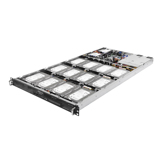
1U12LX Series Chapter 2 Server System Overview his chapter provides diagrams showing the location of important components of the server system. 2.1 System Components Top Cover 2 x Power Supply Units 4 x System Fans 12 x 3.5” HDD Carriers 2 x 2.5”... -
Page 9: Cable Connections
2.2 Cable Connections... - Page 10 1U12LX Series From Cable* 2.5" HDD 1* SB / PSU Power supply cable 2.5" HDD 2* SB / PSU Power supply cable Server Board (SB) see Note see Note Power Supply Unit (PSU1) Power Supply Unit (PSU2) System Fan 4...
- Page 11 Conenctions and cable routing may difer depending on various server boards. Please refer to the Quick Installation Guide to know the exact headers or cables to be connected on the server board you purchase. For more detailed information about server board components, refer to the manual that comes with your server board.
-
Page 12: System Front Panel
1U12LX Series 2.3 System Front Panel Description 2 x USB 2.0 Ports Control Panel Buttons and LEDs 2.4 System Rear Panel Description Power Supply Unit I/O Shield (depends on the speciication of the server board)* Rear Vent* 1 x PCI Express Slot (for the riser card) -
Page 13: Front Control Panel Buttons And Leds
2.5 Front Control Panel Buttons and LEDs Front Control Panel (two types) Description NMI (Nonmaskable Interrupt) Button* System Reset Button LAN1, LAN2 Activity LED* HDD Activity LED* UID Button and LED* Power Button and LED HDD Status and LEDs* (not supported for C2750D4I server board) *Please be noted that the functions are supported depending on the type of the server board. -
Page 14: Power Button
1U12LX Series Power Button Press the power switch button to toggle the system power on and standby/sleep modes. To remove all power from the system completely, disconnect the power cord from the server. Status LED Deinitions Power LED Status Description... -
Page 15: Chapter 3 Hardware Installation And Maintenance
Chapter 3 Hardware Installation and Maintenance his chapter helps you assemble the chassis and install components. Before You Begin Before you work with the server, pay close attention to the “Important Safety Instructions” at the beginning of this manual. 1. Make sure the server is powered of. Power down the server if it is still running. -
Page 16: Server Top Cover
1U12LX Series 3.1 Server Top Cover Removing the Server Top Cover 1. Before removing the top cover, power of the server and unplug the power cord. 2. he system must be operated with the chassis top cover installed to ensure proper cooling. - Page 17 Installing the Server Top Cover 1. Lower the top cover on the chassis, making sure the side latches align with the cutouts. 2. Slide the top cover toward the front. 3. Secure the top cover with the six screws.
-
Page 18: Hard Drive
1U12LX Series 3.2 Hard Drive 3.2.1 Installing a Hard Disk Drive into 3.5" Hard Drive Carrier his system allows the routing of cables behind the HDD base plate and carriers. Be sure to connect all required cables irst before installing any of the 3.5” HDDs. Meanwhile, please well organize your cables and be careful with your cable routing. - Page 19 Installing a 3.5” Hard Drive to the Hard Drive Carrier 1. Place the 3.5" HDD into the carrier with the printed circuit board side facing down. Carefully align the mounting holes in the hard drive and the carrier. 2. Secure the hard drive using the four screws. 3.
- Page 20 1U12LX Series Removing a Hard Disk Drive Base Plate from the Chassis Organize your cables and place them under the hard drive base plates before installing 3.5" HDDs. 1. Remove the screws that secure the hard drive base plate.
- Page 21 3.2.2 Installing a Hard Disk Drive into 2.5" Hard Drive Carrier 1. Please be noted that you can only choose either two 2.5” HDDs or a riser card to be in- stalled in the system. Before installing a 2.5” HDD, make sure the riser card is removed. 2.
- Page 22 1U12LX Series Installing a 2.5” Hard Drive to the Hard Drive Carrier 1. Place 2.5" HDDs into the carrier with the label facing down and the connector ends toward the front of the chassis. Carefully align the mounting holes in the hard drive and the carrier.
- Page 23 4. Place the drive carrier back to the chassis with screw holes aligned. 5. Secure the drive carrier with screws.
-
Page 24: Power Supply
1U12LX Series 3.3 Power Supply he 1U12LX can accommodate two AC or two DC power supplies in the bay at the rear of the chassis. Each unit provides up to 550 Watts of power. Only a single power supply is required for operation, with the second power supply purely as a redundant, load-sharing backup. - Page 25 Removing the Power Supply Unit To remove a failed power supply, identify the failed power supply by checking the power supply LEDs on the PSU. 1. Hold onto the power supply handle while pressing the locking lever towards the power supply handle.
-
Page 26: Add-In Card
1U12LX Series 3.4 Add-In Card 1. You can install an add-in card to the chassis only when you have a riser card to be installed on the server board. 2. Before installing the riser card, be sure to remove the 2.5” HDD carrier irst. - Page 27 4. Install the add-in card into the connector on the riser card. *You need to purchase a compatible riser card seperately if needed. 5. Slide the add-in card attached to the riser card into the add-in card retainer plate. Riser Card Retainer Plate 6.
-
Page 28: System Fan
1U12LX Series 3.5 System Fan Replacing the System Fan 1. Unplug the fan connecter and remove the failed fan. 2. Align the mounting holes on the fan bar with the fan mounts on the replacement fan corners. 3. Gently place the fan on the fan bar. Make sure the fan is well seated. -
Page 29: Backplane
3.6 Backplane Each barebone system supports three 3.5-inch HDD backplanes. he miniSAS/ SATA backplanes serve as the interfaces between the server board and the HDDs. Before removing and installing the backplanes, power of the server and unplug the power cord and make sure all 3.5” HDDs have been removed. For the speciication of the backplane, please refer to the Chapter 4. -
Page 30: Server Board
1U12LX Series 3.7 Server Board Follow the steps below to install the server board to the chassis. 1. Hold the server board only by the edges. 2. Gently place the server board into the chassis. Sit the server board on the server board tray. -
Page 31: Chassis Cables
3.8 Chassis Cables his section lists supported cables for your chassis system. Cable type and quantity vary depending on the server board that comes with your system. 1. MiniSAS to SATA Cable 1 (490mm) (Quantity: 1) Server Board Port 0-3 2. - Page 32 1U12LX Series 3. MiniSAS to SATA Cable 3 (690mm) (Quantity: 1) Server Board Port 8-11 MiniSAS to MiniSAS Cable 1 (220mm) (Quantity: 1) Server Board MiniSAS to MiniSAS Cable 2 (380mm) (Quantity: 1) Server Board MiniSAS to MiniSAS Cable 3 (560mm) (Quantity: 1)
- Page 33 SATA Cable 1 (350mm) (Quantity: 1) SATA HDD Server Board SATA Cable 1 (500mm) (Quantity: 1) SATA HDD Server Board SMBus Cable (900mm) (Quantity: 1) Server Board Front Panel Cable (1000mm) (Quantity: 1)* PANEL1 AUX_PANEL1 NMI_BTN Server Board...
- Page 34 1U12LX Series Fan Cable (130mm) (Quantity: 1) Server Board USB Cable (1080mm) (Quantity: 1) Server Board PMBus Cable (350mm) (Quantity: 1) Server Board BPB Power Cable (160mm) (Quantity: 1) 1. Remove all 3.5” HDDs carriers when you are going to connect various components with cables.
-
Page 35: Chapter 4 Backplane Speciications
Chapter 4 Backplane Speciications Hard Drive Backplanes (BP) ( to connect 4x3 3.5" HDDs) 1U12LIW-BPB1 / 1U12LIW-BPB2 / 1U12LIW-BPB3 Top View MINI_SAS1 SMB_1 SGPIO1 PWR1 PWR2 CON1 CON2 CON3 CON4 Description I2C Address Settings (J2) SGPIO Code Programming Pin (SGPIO1) Debug Header (J1) BMC SMBus Connector (SMB_1) Mini-SAS Connector (MINI_SAS1) - Page 36 1U12LX Series Front Panel Board (FPB) 1U12LIW-FPB1 Top View USB_Header Front + AUX Panel 10 11 Description USB Header (USB_Header) Front and Auxiliary Panel Header (Front + AUX Panel) Front USB 2.0 Connector (Front_USB_1) Front USB 2.0 Connector (Front_USB_2) NMI Button (CON2)
- Page 37 Power Distribution Board (PDB) 1U12LX-PDB Top View ATXPWR1 ATX12V1 BPB_PWR1 PSU_SMB1 CON2 CON1 Description PMBus Connnector (PSU_SMB1) BPB Power Connector (BPB_PWR1) ATX 8pin Power Connector (ATX12V1) ATX 24pin Power Connector (ATXPWR1) Power Supply Connector (CON2) Power Supply Connector (CON1)
- Page 38 1U12LX Series Jumper Setup he illustration shows how jumpers are setup. When the jumper cap is placed on the pins, the jumper is “Short”. If no jumper cap is placed on the pins, the jumper is “Open”. he illustration shows a 3-pin jumper whose pin1 and pin2 are “Short”...
- Page 39 SMB Connector he SMB (SubMiniature (5-pin SMB_1) version B) connector provides (5-pin SMB_2) a communication interface (5-pin SMB_3) between the backplane and the (see p.29, No. 4) motherboard. +3V_SEL Debug Header his header is for debug 3.3V (5-pin J1) purposes. XERS# (see p.29, No.
- Page 40 1U12LX Series BPB Power Connector his connector is used (12-pin ATXPWR1) to connect BPB and the (see p.31, No. 2) power connector on the power distribution board. PMBus Connector PSU SMBus monitors the PSU_CLK PSU_DAT (5-pin PSU_SMB1) status of the power supply.
-
Page 41: Appendix A Installing The Server In A Rack
Appendix A Installing the Server in a Rack This section describes how to rackmount the 1U12LX Series server with slide rail assemblies. he rails installation instructions in this manual are example only, your actual rail assembly procedure may difer slightly . - Page 42 1U12LX Series To slide a chassis rail back into the slide rail assembly, push the blue release button toward the rear, and simultaneously slide the chassis rail into the slide rail assembly until it is locked and cannot be pushed further.
- Page 43 Attaching the Slide Rail Assemblies to the Rack Determine where to attach the slide rails. Make sure you have three holes of free space above the slide rail bracket. For the rack with square mounting holes, insert cage nuts in the holes that you will use on the rack.
- Page 44 1U12LX Series Adjust the brackets to accommodate the depth of the rack. 1 1 U 1 1 U Align the holes on the brackets with the mounting holes you selected on the rack. Tighten the screws to secure the slide rails to the rack. Make sure the rear bracket meets the rear vertical rail of the rack.
- Page 45 Fully tighten the lock nuts on the rear bracket. 1 1 U Sliding the Server into the Rack Ensure that the slide rails are properly and securely attached to the rack. Fully extend the slide rails from the rack by pulling the inner rails out until they are locked and cannot be pulled out further.
- Page 46 1U12LX Series Slide the server slowly and evenly all the way into the cabinet to ensure that the slide assemblies are working correctly. he server is heavy. For safe liting, two or more persons are required to install the server into the rack.
- Page 47 Optional Accessory Please purchase the following optional accessories seperately if needed. Rail Assembly Kit Vendor Model Name SIN JHAO SJ-4095-32-T6 Riser Card Vendor Model Name ASRock Rack 1U12LIW-RB1...
Need help?
Do you have a question about the 1U12LX Series and is the answer not in the manual?
Questions and answers