Table of Contents
Advertisement
Advertisement
Table of Contents

Related Manuals for ASROCK A620M-C


Summary of Contents for ASROCK A620M-C
- Page 2 Contact Information If you need to contact ASRock or want to know more about ASRock, you’re welcome to visit ASRock’s website at http://www.asrock.com; or you may contact your dealer for further information. For technical questions, please submit a support request form at https://event.asrock.com/tsd.asp ASRock Incorporation e-mail: info@asrock.com.tw...
-
Page 3: Table Of Contents
Chapter 1 Introduction Package Contents Specifications Motherboard Layout I/O Panel Block Diagram 802.11ax Wi-Fi 6E Module and ASRock WiFi 2.4/5/6 GHz Antennas Chapter 2 Installation Installing the CPU Installing the CPU Fan and Heatsink Installing Memory Modules (DIMM) Connecting the Front Panel Header... - Page 4 2.14 Smart Switches 2.15 Post Status Checker 2.16 M.2 SSD Module Installation Guide 2.17 Change Screen Brightness for eDP in Windows®...
-
Page 5: Chapter 1 Introduction
ASRock’s website without further notice. If you require technical support related to this motherboard, please visit our website for specific information about the model you are using. You may find the latest VGA cards and CPU support list on ASRock’s website as well. ASRock website http://www.asrock.com. -
Page 6: Specifications
1.2 Specifications Platform • Micro ATX Form Factor • Supports AMD Socket AM5 Ryzen 7000 Series Processors * Please refer to CPU Support List on ASRock's website for more information. (http://www.asrock.com/) Chipset • AMD A620 Memory • Dual Channel DDR5 Memory Technology • 4 x DDR5 DIMM Slots... - Page 7 A620M-C • Gigabit LAN 10/100/1000 Mb/s • Realtek RTL8111H • 802.11ax Wi-Fi 6E Module Wireless • Supports IEEE 802.11a/b/g/n/ac/ax • Supports Dual-Band 2x2 with extended 6GHz band* sup- port * Wi-Fi 6E (6GHz band) will be supported by Microsoft® Win- dows®...
- Page 8 Storage CPU: • 1 x Hyper M.2 Socket (M2_1, Key M), supports type 2260/2280 PCIe Gen4x4 (64 Gb/s) mode* Chipset: • 1 x M.2 Socket (M2_2, Key M), supports type 2260/2280 PCIe Gen3x2 (16 Gb/s) mode* • 1 x M.2 Socket (M2_3, Key M), supports type 2260/2280 PCIe Gen3x2 (16 Gb/s) mode* • 4 x SATA3 6.0 Gb/s Connectors * Supports NVMe SSD as boot disks...
- Page 9 • ErP/EuP ready (ErP/EuP ready power supply is required) • CEC Tier II ready * For detailed product information, please visit our website: http://www.asrock.com Please realize that there is a certain risk involved with overclocking, including adjusting the setting in the BIOS, applying Untied Overclocking Technology, or using third-party overclocking tools.
-
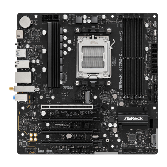
Page 10: Motherboard Layout
1.3 Motherboard Layout Top Side View... - Page 11 A620M-C Back Side View...
- Page 12 No. Description 8 pin 12V Power Connector (ATX12V1) 4 pin 12V Power Connector (ATX12V2) CPU Fan Connector (CPU_FAN1) 2 x 288-pin DDR5 DIMM Slots (DDR5_A1, DDR5_B1) 2 x 288-pin DDR5 DIMM Slots (DDR5_A2, DDR5_B2) Addressable LED Header (ADDR_LED3) RGB LED Header (RGB_LED1) ATX Power Connector (ATXPWR1) Front Panel Type C USB 3.2 Gen1 Header (USB32_TC2) SATA3 Connector (SATA3_1)
-
Page 13: I/O Panel
A620M-C 1.4 I/O Panel No. Description No. Description LAN RJ-45 Port* USB 2.0 Ports (USB_1234) Line In (Light Blue)** USB 3.2 Gen2 Type-A Port (USB32_1) Front Speaker (Lime)** USB 3.2 Gen2 Type-C Port (USB32_TC1) Microphone (Pink)** BIOS Flashback Button Antenna Ports HDMI Port USB 3.2 Gen1 Type-A Ports (USB32_23) -
Page 14: Block Diagram
1.5 Block Diagram... -
Page 15: 802.11Ax Wi-Fi 6E Module And Asrock Wifi 2.4/5/6 Ghz Antennas
A620M-C 1.6 802.11ax Wi-Fi 6E Module and ASRock WiFi 2.4/5/6 GHz Antennas 802.11ax Wi-Fi 6E + BT Module This motherboard comes with an exclusive 802.11 a/b/g/n/ac/ax Wi-Fi 6E + BT module that offers support for 802.11 a/b/g/n/ac/ax Wi-Fi 6E connectivity standards and Bluetooth. - Page 16 WiFi Antennas Installation Guide Step 1 Prepare the WiFi 2.4/5/6 GHz Antennas that come with the package. Step 2 Connect the two WiFi 2.4/5/6 GHz Antennas to the antenna connectors. Turn the antenna clockwise until it is securely connected. Step 3 Set the WiFi 2.4/5/6 GHz Antenna as shown in the illustration.
-
Page 17: Chapter 2 Installation
A620M-C Chapter 2 Installation This is a Micro ATX form factor motherboard. Before you install the motherboard, study the configuration of your chassis to ensure that the motherboard fits into it. Pre-installation Precautions Take note of the following precautions before you install motherboard components or change any motherboard settings. -
Page 18: Installing The Cpu
2.1 Installing the CPU 1. Before you insert the 1718-Pin CPU into the socket, please check if the PnP cap is on the socket, if the CPU surface is unclean, or if there are any bent pins in the socket. Do not force to insert the CPU into the socket if above situation is found. Otherwise, the CPU will be seriously damaged. - Page 19 A620M-C Carefully place the CPU in as flat as possible. Do not drop it.
- Page 20 Make sure the CPU is aligned with the socket before locking it into place. Make sure the black cover plate is always in place until it pops off when closing the socket lever. Please save the cover if the processor is removed. The cover must be placed if you wish to return the motherboard for after service.
-
Page 21: Installing The Cpu Fan And Heatsink
A620M-C 2.2 Installing the CPU Fan and Heatsink After you install the CPU into this motherboard, it is necessary to install a larger heatsink and cooling fan to dissipate heat. You also need to spray thermal grease between the CPU and the heatsink to improve heat dissipation. Make sure that the CPU and the heatsink are securely fastened and in good contact with each other. - Page 23 A620M-C Installing the CPU Cooler (Type 2)
- Page 25 A620M-C +12V *The illustrations shown here are for reference purposes only and may not exactly match the model you purchase.
- Page 26 Installing the CPU Cooler (Type 3)
- Page 27 A620M-C...
- Page 28 *The illustrations shown here are for reference purposes only and may not exactly match the model you purchase.
-
Page 29: Installing Memory Modules (Dimm)
A620M-C 2.3 Installing Memory Modules (DIMM) This motherboard provides four 288-pin DDR5 (Double Data Rate 5) DIMM slots, and supports Dual Channel Memory Technology. 1. For dual channel configuration, you always need to install identical (the same brand, speed, size and chip-type) DDR5 DIMM pairs. -
Page 31: Connecting The Front Panel Header
A620M-C 2.4 Connecting the Front Panel Header Front Panel Wires System Panel Header Power SW (-) RESET SW (+) Power SW (+) RESET SW (-) Power LED (-) HDD LED (-) Power LED (+) HDD LED (+) PANEL1... -
Page 32: Installing The I/O Panel Shield
2.5 Installing the I/O Panel Shield... -
Page 33: Installing The Motherboard
A620M-C 2.6 Installing the Motherboard... -
Page 34: Installing Sata Drives
2.7 Installing SATA Drives Optical Drive SATA Drive SATA Data Cable... - Page 35 A620M-C SATA Power Connector SATA Data Connector...
-
Page 36: Installing A Graphics Card
2.8 Installing a Graphics Card CLICK! - Page 37 A620M-C Expansion Slots (PCIe Slots) There are 4 PCI Express slots on the motherboard. Before installing an expansion card, please make sure that the power supply is switched off or the power cord is unplugged. Please read the documentation of the expansion card and make necessary hardware settings for the card before you start the installation.
-
Page 38: Connecting Peripheral Devices
2.9 Connecting Peripheral Devices... -
Page 39: Connecting The Power Connectors
A620M-C 2.10 Connecting the Power Connectors... -
Page 40: Power On
2.11 Power On... -
Page 41: Jumpers Setup
A620M-C 2.12 Jumpers Setup The illustration shows how jumpers are setup. When the jumper cap is placed on the pins, the jumper is “Short”. If no jumper cap is placed on the pins, the jumper is “Open”. Clear CMOS Jumper (CLRCMOS1) (see p.6, No. -
Page 42: Onboard Headers And Connectors
2.13 Onboard Headers and Connectors Onboard headers and connectors are NOT jumpers. Do NOT place jumper caps over these headers and connectors. Placing jumper caps over the headers and connectors will cause permanent damage to the motherboard. System Panel Header (9-pin PANEL1) (see p.6, No. - Page 43 A620M-C Power LED and Speaker Header (7-pin SPK_PLED1) (see p.6, No. 16) Please connect the chassis power LED and the chassis speaker to this header. SPK_PLED1 SPEAKER DUMMY DUMMY PLED+ PLED+ PLED- Serial ATA3 Connectors Vertical: (SATA3_1) (see p.6, No. 10) (SATA3_2) (see p.6, No.
- Page 44 USB 2.0 Headers (9-pin USB_5_6) (see p.6, No. 21) (9-pin USB_7_8) (see p.6, No. 22) There are two headers on this motherboard. Each USB 2.0 header can support two ports. USB_7_8 USB_PWR DUMMY USB_PWR USB_5_6 USB_PWR DUMMY USB_PWR USB 3.2 Gen1 Headers (19-pin USB32_4_5) (see p.6, No.
- Page 45 A620M-C Front Panel Type C USB 3.2 Gen1 Header (20-pin USB32_TC2) (see p.6, No. 9) There is one Front Panel Type C USB 3.2 Gen1 Header on this motherboard. This header is used for connecting a USB 3.2 Gen1 module for additional USB 3.2 Gen1 ports.
- Page 46 Chassis/Water Pump Fan Connectors (4-pin CHA_FAN1/WP) (see p.6, No.24) (4-pin CHA_FAN2/WP) (see p.6, No. 23) (4-pin CHA_FAN3/WP) (see p.6, No. 20) This motherboard provides three 4-Pin water cooling chassis fan connectors. If you plan to connect a 3-Pin chassis water cooler fan, please connect it to Pin 1-3. CHA_FAN3/WP FAN_VOLTAGE CHA_FAN_SPEED...
- Page 47 A620M-C CPU Fan Connector (4-pin CPU_FAN1) (see p.6, No. 3) This motherboard provides a 4-Pin CPU fan (Quiet Fan) connector. If you plan to connect a 3-Pin CPU fan, please connect it to Pin 1-3. CPU_FAN1 +12V CPU_F AN_SPEED FAN_SPEED_CONTROL CPU/Water Pump Fan Connector (4-pin CPU_FAN2/WP) (see p.6, No.
- Page 48 ATX Power Connector (24-pin ATXPWR1) (see p.6, No. 8) This motherboard provides a 24-pin ATX power connector. To use a 20-pin ATX power supply, please plug it along Pin 1 and Pin 13. ATXPWR1 ATX 12V Power Connector (8-pin ATX12V1) (see p.6, No. 1) This motherboard provides a 8-pin ATX 12V power connector.
- Page 49 A620M-C ATX 12V Power Connector (4-pin ATX12V2) (see p.6, No. 2) Please connect an ATX 12V power supply to this connector. *The power supply plug fits into this connector in only one orientation. *Connecting an ATX 12V 4-pin cable to ATX12V2 is optional.
- Page 50 RGB LED Header (4-pin RGB_LED1) (see p.6, No. 7) This RGB header is used to connect RGB LED extension cable which allow users to choose from various LED lighting effects. Caution: Never install the RGB LED cable in the wrong orientation; otherwise, the cable may be damaged.
- Page 51 A620M-C Addressable LED Headers (3-pin ADDR_LED1) (see p.6, No. 25) (3-pin ADDR_LED2) (see p.6, No. 26) (3-pin ADDR_LED3) (see p.6, No. 6) These headers are used to connect Addressable LED extension cables which allow users to choose from various LED lighting effects.
- Page 52 1. Never install the RGB LED cable in the wrong orientation; otherwise, the cable may be damaged. 2. Before installing or removing your RGB LED cable, please power off your system and unplug the power cord from the power supply. Failure to do so may cause dam- ages to motherboard components.
- Page 53 A620M-C eDP Signal Connector (40-pin EDP1) (see p.7, No. 29) This connector on the bottom side of the motherboard is for an LCD monitor that supports an internal embedded DisplayPort (eDP). *Please refer to page 55 for further instructions on how to adjust the brightness.
- Page 54 2.14 Smart Switches The motherboard has one smart switch: BIOS Flashback Button, allowing users to flash the BIOS. BIOS Flashback Button (BIOS_FB1) (see p.9, No. 10) BIOS Flashback Button allows users to flash the BIOS. BIOS_FB1 USB BIOS Flashback port...
- Page 55 A620M-C ASRock BIOS Flashback feature allows you to update BIOS without powering on the system, even without CPU. Before using the BIOS Flashback function, please suspend BitLocker and any encryp- tion or security relying on the TPM. Make sure that you have already stored and backup-ed the recovery key.
- Page 56 2.15 Post Status Checker Post Status Checker (PSC) diagnoses the computer when users power on the machine. It emits a red light to indicate whether the CPU, memory, VGA or storage is dysfunctional. The lights go off if the four mentioned above are functioning normally. It is normal for the DRAM status LED to blink during memory training.
- Page 57 A620M-C 2.16 M.2 SSD Module Installation Guide The M.2 is a small size and versatile card edge connector that aims to replace mPCIe and mSATA. The Hyper M.2 Socket (M2_1, Key M) supports type 2260/2280 PCIe Gen4x4 (64 Gb/s) mode. The M.2 Sockets (M2_2 and M2_3, Key M) support type 2260/2280 PCIe Gen3x2 (16 Gb/s) mode.
- Page 58 Tighten the screw with a screwdriver to secure the module into place. Please do not overtighten the screw as this might damage the module. NUT2 NUT1 For the latest updates of M.2 SSD module support list, please visit our website for details: http://www.asrock.com...
- Page 59 A620M-C 2.17 Change Screen Brightness for eDP in Windows® This section explains how to change screen brightness in Windows® when you use an eDP panel. The following is a setup example for Windows® 11. Setup procedures may vary from different operating systems.
- Page 60 Step 3 You might also see another check box displayed: Help improve battery by optimizing the content shown and brightness. Select the check box to turn on the content adaptive brightness control if needed.
- Page 61 In no event shall ASRock, its directors, officers, employees, or agents be liable for any indirect, special, incidental, or consequential damages (including damages for loss of profits, loss of business, loss of data, interruption of business and the like), even if ASRock has been advised of the possibility of such damages arising from any defect or error in the documentation or product.
- Page 62 If you require assistance please call ASRock Tel : +886-2-28965588 ext.123 (Standard International call charges apply)
- Page 63 ASRock follows the green design concept to design and manufacture our products, and makes sure that each stage of the product life cycle of ASRock product is in line with global environmental regulations. In addition, ASRock disclose the relevant information based on regulation requirements.
- Page 64 Operations in the 5.15-5.35GHz band are restricted to indoor usage only. Radio transmit power per transceiver type Function Frequency Maximum Output Power (EIRP) 2400-2483.5 MHz 18.5 + / -1.5 dbm 5150-5250 MHz 21.5 + / -1.5 dbm 18.5 + / -1.5 dbm (no TPC) WiFi 5250-5350 MHz 21.5 + / -1.5 dbm (TPC)
Need help?
Do you have a question about the A620M-C and is the answer not in the manual?
Questions and answers