
Related Manuals for Timeguard MLTP180BK


Summary of Contents for Timeguard MLTP180BK
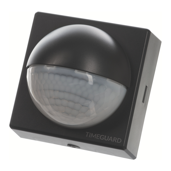
- Page 1 180° Tamper-proof Wall Mounted PIR Model: MLTP180BK – Black Model: MLTP180WH – White...
-
Page 2: General Information
1. General Information These instructions should be read carefully and retained for further reference and maintenance. 2. Safety • Before installation or maintenance, ensure the mains supply to the PIR sensor is switched off and the circuit supply fuses are removed or the circuit breaker turned off. -
Page 3: Selecting A Location
4. Selecting a Location • Careful positioning of the sensor will be required to ensure optimum performance. The mounting height for the sensor should be 2.5m. See diagram A. • The sensor is more sensitive to movement ACROSS its field of vision than to movement directly TOWARDS. -
Page 4: Installation
5. Installation 5.1 Ensure the mains supply is switched OFF and the circuit supply fuses are removed or the circuit breaker turned OFF (See image 1). 5.2 An isolating switch should be installed to enable the power to be switched ON and OFF for maintenance purposes and to activate the manual/auto override function. - Page 5 5.5 Undo the 4 fixing screws and remove the PIR sensor from the back box (See image 4). 5.6 Mark the position of the mounting holes on the wall using the back box as a template (See image 5). Drill the holes ensuring not to infringe with any gas/water pipes or electrical cables that may be hidden below the surface.
- Page 6 5.8 Fix the back box to the wall using the 2x mounting screws, making sure it is the correct way up. Take care not to over-tighten the screws to prevent damage to the back box. If using a power screwdriver, use the lowest torque setting (See image 7).
-
Page 7: Connection Diagram
6. Connection Diagram • Connect the cables to the terminal block as follows; 230V AC 50Hz MAINS SUPPLY ISOLATION SWITCH LOOP TERMINAL 230V 50Hz Mains Supply Live Supply (Brown or Red) to Neutral Supply (Blue or Black) to A ‘Loop Terminal’ is provided should a 3 core cable be used. Load Switch Live (Brown or Red) to Neutral Load (Blue or Black) to... - Page 8 7. Setting Up Walk Test Procedure (Test Mode) • Make sure the PIR sensor is set to Test Mode i.e. the TIME ON Adjustment to the minimum (fully anti-clockwise), and the Lux Level set the Sun symbol (fully clockwise). • Turn the power to the unit ON. The lamp will immediately illuminate as the unit goes through its ‘warm-up’...
- Page 9 Setting Up for Automatic Operation (Auto Mode) • When walk tests are complete, the unit can be adjusted for automatic operation. • The TIME ON adjustment controls how long the unit remains illuminated following activation and after all motion ceases. •...
-
Page 10: Manual Override
• Make sure the font cover clicks into place. Lock the captive latch located on the bottom of the sensor using a 2.5mm Allen key, by pushing up fully and then turning clockwise (quarter turn), so the dot indicator aligns with the ‘Locked’... -
Page 11: Year Guarantee
Note: A proof of purchase is required in all cases. For all eligible replacements (where agreed by Timeguard) the customer is responsible for all shipping/postage charges outside of the UK. All shipping costs are to be paid in advance before a replacement... - Page 12 If you experience problems, do not immediately return the unit to the store. Telephone the Timeguard Customer Helpline; HELPLINE 020 8450 0515 or email helpline @ timeguard.com Qualified Customer Support Co-ordinators will be on-line to assist in resolving your query.
Need help?
Do you have a question about the MLTP180BK and is the answer not in the manual?
Questions and answers