Table of Contents

Related Manuals for BUSCH COBRA NS 0070-0600 C


Summary of Contents for BUSCH COBRA NS 0070-0600 C
- Page 1 Instruction Manual COBRA ATEX Dry Screw Vacuum Pumps NS 0600 C (water-cooled version) Ateliers Busch S.A. Zone industrielle, 2906 Chevenez Switzerland 0870219588/-0000_en / Original instructions / Modifications reserved 20/11/2019...
-
Page 2: Table Of Contents
Table of Contents Table of Contents 1 Safety........................... 4 2 Product Description ..................... 5 2.1 Operating Principle....................6 2.2 Application ......................6 2.3 Start Controls ....................... 6 2.4 Standard Features....................6 2.4.1 Water Cooling ...................7 2.4.2 Sealing Systems ..................7 2.4.3 Barrier Gas System ..................7 2.4.4 Resistance Thermometer................7 2.5 Optional Accessories..................... - Page 3 Table of Contents 7.6.1 Procedure A....................31 7.6.2 Procedure C....................31 7.6.3 Procedure E ....................31 8 Overhaul........................32 9 Decommissioning ......................32 9.1 Dismantling and Disposal..................32 10 Spare Parts ........................33 11 Troubleshooting......................34 12 Technical Data ......................36 13 Cooling Liquid ......................36 14 Oil ..........................
-
Page 4: Safety
Safety Prior to handling the machine, this instruction manual should be read and understood. If anything needs to be clarified, please contact your Busch representative. Read this manual carefully before use and keep for future reference. This instruction manual remains valid as long as the customer does not change anything on the product. -
Page 5: Product Description
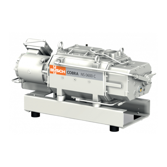
Product Description | 2 Product Description TSA+/0104 NP1 NP2 ODP, MP Plate heat exchanger Cooling liquid drain plug Cooling liquid fill plug Cooling liquid pump Cooling liquid vent plug Eye bolt Cooling water inlet Cooling water outlet Suction connection Magnetic plug Motor terminal box Nameplate Oil drain plug... -
Page 6: Operating Principle
(NP), see Explanation of ATEX Classification [► 8]. Conveying of other media leads to an increased thermal and/or mechanical load on the machine and is permissible only after a consultation with Busch. The machine is not intended for the placement in a potentially explosive environment ac- cording to the data given on the nameplate of the machine (NP), see Explanation of ATEX Classification [► 8]. -
Page 7: Standard Features
Product Description | 2 2.4 Standard Features 2.4.1 Water Cooling The machine is cooled by a cooling liquid circuit in the cylinder cover and cylinder. The cooling liquid pump (CLP) allows a recirculating flow in the cooling liquid chamber. The cooling liquid is cooled by a plate heat exchanger (PHE) which must be connected to the water main. -
Page 8: Terminal Box
Risk of severe injury! Risk of explosion! • Make sure that the recommendations described in this manual correspond to the ATEX marking written on the nameplate (NP). • If anything needs to be clarified, please contact your Busch representative. 8 / 40 0870219588_NS0600C_WCV_Ex_-0000_IM_en... -
Page 9: Atex Classifications And Associated Accessories
Product Description | 2 The safety concept is based on the prevention of sparks and excessive temperatures by means of various accessories. The monitoring devices must be integrated into the system control such that operation of the machine will be inhibited if the safety limit values are exceeded. 2.7.1 ATEX Classifications and Associated Accessories The following table defines the obligatory accessories depending on the ATEX classifica- tion. -
Page 10: P&Id "Piping And Instrumentation Diagram
2 | Product Description 2.7.2 P&ID "Piping and Instrumentation Diagram" P&ID G1/4 DN100 ISO-K Flushing liquid device DN100 PN16 0503 0201 Purge gas system 0202 TSA+ 0501 0104 G1/2 Barrier gas system 0504 G1/2 55°C Dilution gas system PSA+ 0301 = optional 0301 TSA+... -
Page 11: Transport
Transport | 3 Transport WARNING Suspended load. Risk of severe injury! • Do not walk, stand or work under suspended loads. WARNING Lifting the machine using the motor eye bolt. Risk of severe injury! • Do not lift the machine using the eye bolt fitted to the motor. Only lift the machine as shown. -
Page 12: Installation
Connection [► 14]. If the machine is installed at an altitude greater than 1000 meters above sea level: • Contact your Busch representative, the motor should be derated or the ambient temperature limited. If additional electrical components not included in scope of delivery should be added: •... -
Page 13: Connecting Lines / Pipes
– DN100 ISO-K, DIN 28404 or DN100 ISO-F, DIN 28404 If the machine is used as part of a vacuum system: • Busch recommends the installation of an isolation valve in order to prevent the machine from turning backwards. 5.2.2 Discharge Connection... -
Page 14: Cooling Water Connection
5 | Installation • Make sure that the discharged gas will flow without obstruction. Do not shut off or throttle the discharge line or use it as a pressurised air source. • Make sure that the counter pressure (also termed back pressure) at the discharge con- nection (OUT) does not exceed the maximum allowable discharge pressure, see Tech- nical Data [► 36]. -
Page 15: Barrier Gas System Connection
Installation | 5 5.2.4 Barrier Gas System Connection With nitrogen panel FME, FS Barrier gas connection Flow meter Flow switch Manometer Solenoid valve Nitrogen panel Pressure regulating valve • Connect the barrier gas connection (BGC) to the gas supply. Connection size: –... -
Page 16: Earth Connection
Risk of premature failure! Loss of efficiency! • Only use an oil type which has previously been approved and recommended by Busch. For oil type and oil capacity see Technical Data [► 36] and Oil [► 36]. Oil filling at the motor side... - Page 17 Last oil change __ / __ / ____ Oil type see nameplate Change interval see instruction manual If there is no sticker (part no. 0565 568 959) on the machine: • Order it from your Busch representative. 0870219588_NS0600C_WCV_Ex_-0000_IM_en 17 / 40...
-
Page 18: Filling Cooling Liquid
• Provide an overload protection according to EN 60204-1 for the motor. • Make sure that the motor of the machine will not be affected by electric or electro- magnetic disturbance from the mains; if necessary seek advice from Busch. • Connect the protective earth conductor. -
Page 19: Wiring Diagram Three-Phase Motor (Pump Drive)
Installation | 5 NOTICE The admissible motor nominal speed exceeds the recommendation. Risk of damage to the machine! • Check the admissible motor nominal speed (n ) on the nameplate of the machine (NP). • Make sure to comply with it. •... -
Page 20: Electrical Connection Of The Monitoring Devices
• Switch any two of the motor phase wires. 5.7 Electrical Connection of the Monitoring Devices NOTE In order to prevent potential nuisance alarms, Busch allows that the control system is configured with a time delay of 2 seconds. NOTE The accessories below are considered as standard. -
Page 21: Wiring Diagram Resistance Thermometer
Installation | 5 5.7.1 Wiring Diagram Resistance Thermometer Part no.: Wiring with transmitter: PT100: 0651 550 436 (option) Transmitter: 0643 536 800 (option) Supplier reference: PT100: Albert Balzer AG ref. TWBa-ADX50XG1/4X90DACB Transmitter: Endress+Hauser 1 = Brown ; 2 = Blue ref. TMT 187-B41FJA Maintenance procedure: Wiring without transmitter: Procedure A [► 31] P&ID position:... -
Page 22: Wiring Diagram Pressure Transmitter
A warning signal can be set prior the (PSA+/0301) = 0.2* bar ► 13.6 mA trip trip signal. *1200 hPa (mbar) abs. 5.7.3 Wiring Diagram Flow Switch Part no.: No Busch ref. (integrated into the 1 (+) flow meter) Supplier reference: Pepperl+Fuchs RC15-14-N3 2 (-) Maintenance procedure: 1 = Brown ;... -
Page 23: Flowchart
Installation | 5 5.8 Flowchart The machine safety depends on the monitoring accessories sequencing according to the following flowchart. Start Warning: T < T warning? T < T trip? High oil temperature A-side Warning: T < T trip? T < T warning? High gas temperature ! Barrier gas flow sufficient? -
Page 24: Commissioning
6 | Commissioning Commissioning WARNING The machine is still running after a monitoring device has tripped. Risk of severe injury! Risk of explosion! • Follow the Trip Procedure. NOTICE The machine can be shipped without oil. Operation without oil will ruin the machine in short time! •... -
Page 25: Conveying Condensable Vapours
Maintenance | 7 • Turn on the barrier gas supply. • Adjust the barrier gas pressure and volume flow. • Switch on the machine. • Make sure that the maximum permissible number of starts does not exceed 2 starts per hour. Those starts should be spread within the hour. •... -
Page 26: Maintenance Schedule
Risk of injuries! Risk of premature failure and loss of efficiency! • Respect the maintenance intervals or ask your Busch representative for service. • Shut down the machine and lock against inadvertent start up. • Turn off the water supply. -
Page 27: Oil Level Inspection
• Fill up if necessary, see Filling Cooling Liquid [► 18]. 7.4 Oil Change NOTICE Use of an inappropriate oil. Risk of premature failure! Loss of efficiency! • Only use an oil type which has previously been approved and recommended by Busch. 0870219588_NS0600C_WCV_Ex_-0000_IM_en 27 / 40... - Page 28 7 | Maintenance Oil draining at the motor side Cleaning cloth Magnetic plug Magnetic plug Cleaning cloth Drain pan Oil draining at the suction side Magnetic plug Cleaning cloth Drain pan 28 / 40 0870219588_NS0600C_WCV_Ex_-0000_IM_en...
- Page 29 Maintenance | 7 For oil type and oil capacity see Technical Data [► 36] and Oil [► 36]. Oil filling at the motor side Check oil level Oil filling at the suction side Check oil level When the oil filling is achieved: •...
-
Page 30: Cooling Liquid Change
__ / __ / ____ Oil type see nameplate Change interval see instruction manual If there is no sticker (part no. 0565 568 959) on the machine: • Order it from your Busch representative. 7.5 Cooling Liquid Change 30 / 40 0870219588_NS0600C_WCV_Ex_-0000_IM_en... -
Page 31: Calibration Procedure Of The Electrical Devices
Maintenance | 7 For cooling liquid type and cooling liquid capacity see Technical Data [► 36] and Cooling Liquid [► 36]. Fill up to the top of the vent orifice 7.6 Calibration Procedure of the Electrical Devices 7.6.1 Procedure A • Remove the resistance thermometer from the machine. •... -
Page 32: Overhaul
• Decontaminate the machine as much as possible and state the contamination status in a ‘Declaration of Contamination’. Busch will only accept machines that come with a completely filled in and legally binding signed ‘Declaration of Contamination’. (Form downloadable from www.buschvacuum.com) Decommissioning •... -
Page 33: Spare Parts
• The exclusive use of Busch genuine spare parts and consumables is recommended for the correct functioning of the machine and to validate the warranty. There is no standard spare parts kits available for this product, if you require Busch gen- uine parts: •... -
Page 34: Troubleshooting
Busch). Solid foreign matter has • Remove the solid foreign entered the machine. matter or repair the ma- chine (contact Busch). • Install an inlet filter if ne- cessary. A temperature sensor has • Let the machine cool reached the switch point. - Page 35 Oil Change [► 27]. The machine runs too hot. • See problem "The ma- chine runs too hot". For the solution of problems not mentioned in the troubleshooting chart contact your Busch representative. 0870219588_NS0600C_WCV_Ex_-0000_IM_en 35 / 40...
-
Page 36: Technical Data
12 | Technical Data 12 Technical Data NS 0600 C Pumping speed m³/h 600 / 600 (50Hz / 60Hz) Ultimate pressure (without gas ballast) hPa (mbar) abs. ≤0.01 Nominal motor rating 15 / 15 (50Hz / 60Hz) Nominal motor speed 3000 / 3600 (50Hz / 60Hz) Noise level (EN ISO 2151) -
Page 37: Eu Declaration Of Conformity
This Declaration of Conformity and the CE-mark affixed to the nameplate are valid for the machine within the Busch scope of delivery. This Declaration of Conformity is issued under the sole responsibility of the manufacturer. When this machine is integrated into a superordinate machinery the manufacturer of the superordinate machinery (this can be the operating company, too) must conduct the conformity assessment process for the superordinate machine or plant, issue the Declaration of Conformity for it and affix the CE-mark. - Page 38 Note...
- Page 39 Note...
- Page 40 Colombia Korea South Africa www.buschvacuum.com/co www.buschvacuum.com/kr www.buschvacuum.com/za info@buschvacuum.co busch@busch.co.kr info@busch.co.za Czech Republic Malaysia Spain www.buschvacuum.com/cz www.busch.com.my www.buschvacuum.com/es info@buschvacuum.cz busch@busch.com.my contacto@buschiberica.es Denmark Mexico Sweden www.buschvacuum.com/dk www.buschvacuum.com/mx www.buschvacuum.com/se info@busch.dk info@busch.com.mx info@busch.se www.buschvacuum.com 0870219588/-0000_en / © Ateliers Busch S.A.
Need help?
Do you have a question about the COBRA NS 0070-0600 C and is the answer not in the manual?
Questions and answers