BUSCH COBRA NC 0630 C Instruction Manual
Dry screw vacuum pumps, air-cooled version
Hide thumbs
Also See for COBRA NC 0630 C:
- Instruction manual (52 pages) ,
- Installation and maintenance instructions manual (20 pages) ,
- Instructions manual (44 pages)

Related Manuals for BUSCH COBRA NC 0630 C


Summary of Contents for BUSCH COBRA NC 0630 C
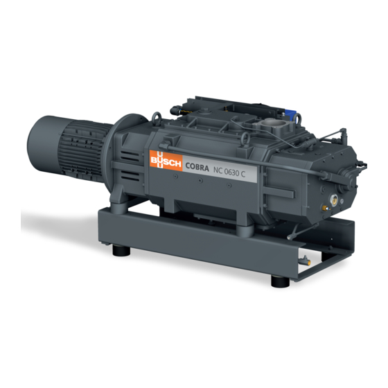
- Page 1 Instruction Manual COBRA Dry Screw Vacuum Pumps NC 0630 C (air-cooled version) Ateliers Busch S.A. Zone industrielle, 2906 Chevenez Switzerland 0870567093/A0002_en / Original instructions / Modifications reserved 04/05/2018...
-
Page 2: Table Of Contents
Table of Contents Table of Contents 1 Safety........................... 4 2 Product Description ..................... 5 2.1 Operating Principle....................6 2.2 Application ......................6 2.3 Standard Features....................6 2.3.1 Air Cooling ....................6 2.3.2 Temperature Switch...................6 2.3.3 Thermometer.....................7 2.3.4 Sealing Systems ..................7 2.4 Optional Accessories..................... 7 2.4.1 Inlet Filter ....................7 2.4.2 Gas Ballast Valve..................7 2.4.3 Silencer ......................7... - Page 3 Table of Contents 7.5 Oil Change ......................26 7.6 Cooling Liquid Change ..................29 8 Overhaul........................30 9 Decommissioning ......................31 9.1 Dismantling and Disposal..................31 10 Spare Parts ........................31 11 Troubleshooting......................32 12 Technical Data ......................34 13 Cooling Liquid ......................34 14 Oil ..........................
-
Page 4: Safety
Safety Prior to handling the machine, this instruction manual should be read and understood. If anything needs to be clarified, please contact your Busch representative. Read this manual carefully before use and keep for future reference. This instruction manual remains valid as long as the customer does not change anything on the product. -
Page 5: Product Description
Product Description | 2 Product Description CLV1 CLV2 ODP, MP Air-water heat exchanger Axial fan Condensate drain Cooling liquid drain plug Cooling liquid fill plug Cooling liquid sight glass Cooling liquid pump CLV1 Cooling liquid vent plug (machine) CLV2 Cooling liquid vent valve (heat exchanger) Eye bolt Gas ballast valve Suction connection... -
Page 6: Operating Principle
Conveying of other media leads to an increased thermal and/or mechanical load on the machine and is permissible only after a consultation with Busch. The machine is intended for the placement in a non-potentially explosive environment. The machine is capable of maintaining ultimate pressure, see Technical Data [► 34]. -
Page 7: Thermometer
Product Description | 2 The machine must be stopped when the temperature switch trips (100 °C). 2.3.3 Thermometer The thermometer allows a visual display of the cooling liquid temperature. 2.3.4 Sealing Systems The machine is equipped with labyrinth seals on the motor side and suction side. Other sealing systems are optionally available, see Mechanical Seals [► 7]. -
Page 8: Liquid Flushing Device
3 | Transport The following devices are available: – The barrier gas system for sealing systems on motor side. This device is equipped with a flow switch integrated to the flow meter to switch off the machine if the ni- trogen volume flow drops below the minimum set flow value. -
Page 9: Storage
Storage | 4 WARNING Lifting the machine using the motor eye bolt. Risk of severe injury! • Do not lift the machine using the eye bolt fitted to the motor. Only lift the machine as previously shown. • Check the machine for transport damage. If the machine is secured to a base plate: •... -
Page 10: Connecting Lines / Pipes
If a purge gas system or a liquid flushing device being installed: – DN100 PN16, EN 1092-1 If the machine is used as part of a vacuum system: • Busch recommends the installation of an isolation valve in order to prevent the machine from turning backwards. 10 / 36... -
Page 11: Discharge Connection
Installation | 5 5.2.2 Discharge Connection Connection size: At the machine discharge connection: – DN100 ISO-K, DIN 28404 At the silencer (SI) discharge connection (two optional versions available): – DN80 PN16 + ANSI/ASME B16.5-3” class 150 lbs – R3 • Make sure that the discharged gas will flow without obstruction. Do not shut off or throttle the discharge line or use it as a pressurised air source. -
Page 12: Dilution Gas System Connection (Optional)
5 | Installation Flow switch Manometer Solenoid valve Nitrogen panel Pressure regulating valve • Connect the barrier gas connection (BGC) to the gas supply. Connection size: – G1/4, ISO 228-1 Version with nitrogen panel: • Electrically connect the solenoid valve (MV), see Wiring Diagram Solenoid Valve [► 19]. -
Page 13: Purge Gas System Connection (Optional)
Installation | 5 Gas type Dry nitrogen Gas temperature °C 0 ... 60 Maximum gas pressure Recommended pressure setting at the pressure regulating valve (PRV) Filtration µm Recommended flow rate SLM* * standard litre per minute 5.2.5 Purge Gas System Connection (Optional) FME, FR Purge gas connection Flow meter... -
Page 14: Filling Oil
Risk of premature failure! Loss of efficiency! • Only use an oil type which has previously been approved and recommended by Busch. For oil type and oil capacity see Technical Data [► 34] and Oil [► 34]. Oil filling at the motor side... - Page 15 • Write down the oil change date on the sticker. Last oil change __ / __ / ____ Oil type see nameplate Change interval see instruction manual If there is no sticker on the pump: • Order it from your Busch representative. 0870567093_NC0630C_ACV_A0002_IM_en 15 / 36...
-
Page 16: Filling Cooling Liquid
5 | Installation 5.4 Filling Cooling Liquid For cooling liquid type and cooling liquid capacity see Technical Data [► 34] and Cooling Liquid [► 34]. Radiator vent valve key Fill up to the top of the vent orifice Resume cooling liquid filling Close the cooling liquid vent valve (CLV2) when the... -
Page 17: Fitting The Coupling
• Provide overload protection according to EN 60204-1 for the motor. • Make sure that the motor of the machine will not be affected by electric or electro- magnetic disturbance from the mains; if necessary seek advice from Busch. • Connect the protective earth conductor. -
Page 18: Wiring Diagram Three-Phase Motor (Pump Drive)
5 | Installation NOTICE The admissible motor nominal speed exceeds the recommendation. Risk of damage to the machine! • Check the admissible motor nominal speed (n ) on the nameplate of the machine (NP). • Make sure to comply with it. •... -
Page 19: Wiring Diagram Solenoid Valve (Optional)
Installation | 5 Delta connection, multi-voltage motor with 12 pins (middle voltage): NOTICE Incorrect direction of rotation. Risk of damage to the machine! • Operation in the wrong direction of rotation can destroy the machine in a short time! Prior to start-up, ensure that the machine is operated in the right direction. The intended rotation direction of the motor is defined by the illustration below: •... -
Page 20: Wiring Diagram Heat Exchanger Fan Motor
• Switch any two of the motor phase wires. 5.9 Electrical Connection of the Monitoring Devices NOTE In order to prevent potential nuisance alarms, Busch recommends that the control system is configured with a time delay of at least 10 seconds. 20 / 36... -
Page 21: Wiring Diagram Temperature Switch
Commissioning | 6 5.9.1 Wiring Diagram Temperature Switch Part no.: 0651 541 566 U = 250 VAC ; I = 2.5 A ► cosφ = 1 U = 250 VAC ; I = 1.6 A ► cosφ = 0.6 U = 48 VDC ; I = 1.25 A Contact : Normally closed 1 = White ;... -
Page 22: Conveying Condensable Vapours
6 | Commissioning NOTICE Running without air-cooled system. Risk of damage to the machine! • Make sure that the fan motor of the heat exchanger (AHE) is running when the ma- chine is started. CAUTION During operation the surface of the machine may reach temperatures of more than 70°C. -
Page 23: Liquid Flushing Procedure
Commissioning | 6 START • Open the inlet Close the gas ballast Open the gas ballast valve valve* 30 minutes 30 minutes Warm up the valve* or the • Perform the process machine dilution gas sytem* • Close the inlet the dilution gas (solenoid valve) valve... -
Page 24: Maintenance
Risk of premature failure! Loss of efficiency! • Respect the maintenance intervals or ask your Busch representative for service. • Shut down the machine and lock against inadvertent start up. If the machine is equipped with a barrier gas system: •... -
Page 25: Oil Level Inspection
• Check the cooling liquid level, see Cooling Liquid Level Inspection [► 25]. • Check the machine for oil leaks - in case of leaks have the machine repaired (contact Busch). Yearly • Carry out a visual inspection and clean the machine from dust and dirt. -
Page 26: Replacing The Gas Ballast Filter (Optional)
7 | Maintenance 7.4 Replacing the Gas Ballast Filter (Optional) Busch genuine spare parts Gas ballast filter: part no. 0562 550 434 Discard the part 7.5 Oil Change NOTICE Use of an inappropriate oil. Risk of premature failure! Loss of efficiency! •... - Page 27 Maintenance | 7 Oil draining at the motor side Magnetic plug Cleaning cloth Drain pan Oil draining at the suction side Magnetic plug Cleaning cloth Drain pan 0870567093_NC0630C_ACV_A0002_IM_en 27 / 36...
- Page 28 7 | Maintenance For oil type and oil capacity see Technical Data [► 34] and Oil [► 34]. Oil filling at the motor side Check oil level Oil filling at the suction side Check oil level When the oil filling is achieved: •...
-
Page 29: Cooling Liquid Change
Last oil change __ / __ / ____ Oil type see nameplate Change interval see instruction manual If there is no sticker on the pump: • Order it from your Busch representative. 7.6 Cooling Liquid Change 0870567093_NC0630C_ACV_A0002_IM_en 29 / 36... -
Page 30: Overhaul
Risk of premature failure! Loss of efficiency! • It is highly recommended that any dismantling of the machine that goes beyond any- thing that is described in this manual should be done through Busch. WARNING Machines contaminated with hazardous material. -
Page 31: Decommissioning
• The exclusive use of Busch genuine spare parts and consumables is recommended for the proper function of the machine and for granting of warranty. There is no standard spare parts kits available for this product, if you require Busch gen- uine parts: •... -
Page 32: Troubleshooting
Busch). Solid foreign matter has • Remove the solid foreign entered the machine. matter or repair the ma- chine (contact Busch). • Install an inlet filter if ne- cessary. The temperature switch (TS) • Let the machine cool reached the switch point. - Page 33 Oil Change [► 26]. The machine runs too hot. • See problem "The ma- chine runs too hot". For the solution of problems not mentioned in the troubleshooting chart contact your Busch representative. 0870567093_NC0630C_ACV_A0002_IM_en 33 / 36...
-
Page 34: Technical Data
12 | Technical Data 12 Technical Data NC 0630 C Pumping speed m³/h 630 / 630 (50Hz / 60Hz) Ultimate pressure (without gas ballast) hPa (mbar) abs. ≤0.01 Ultimate pressure (with gas ballast) hPa (mbar) abs. ≤0.1 Nominal motor rating 15 / 17 (50Hz / 60Hz) Nominal motor speed... -
Page 35: Eu Declaration Of Conformity
This Declaration of Conformity and the CE-mark affixed to the nameplate are valid for the machine within the Busch scope of delivery. This Declaration of Conformity is issued under the sole responsibility of the manufacturer. When this machine is integrated into a superordinate machinery the manufacturer of the superordinate machinery (this can be the operating company, too) must conduct the conformity assessment process for the superordinate machine or plant, issue the Declaration of Conformity for it and affix the CE-mark. - Page 36 Czech Republic Netherlands Turkey www.buschvacuum.cz www.busch.nl www.buschvacuum.com Denmark New Zealand United Arab Emirates www.busch.dk www.busch.com.au www.busch.ae Finland Norway United Kingdom www.busch.fi www.busch.no www.busch.co.uk France Peru www.busch.fr www.busch.com.pe www.buschusa.com Germany Poland www.busch.de www.busch.com.pl www.buschvacuum.com 0870567093/A0002_en / © Ateliers Busch S.A.
Need help?
Do you have a question about the COBRA NC 0630 C and is the answer not in the manual?
Questions and answers