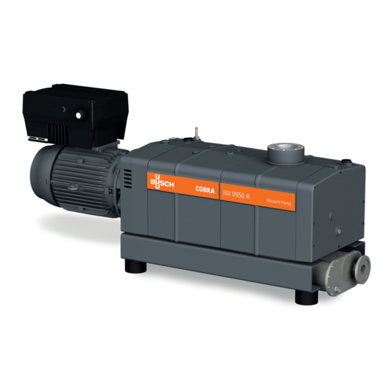
BUSCH COBRA NX 0950 A Instruction Manual
Dry screw vacuum pumps, water-cooled version
Hide thumbs
Also See for COBRA NX 0950 A:
- Instructions manual (44 pages) ,
- Instruction manual (48 pages) ,
- Instruction manual (44 pages)
Table of Contents

Related Manuals for BUSCH COBRA NX 0950 A


Summary of Contents for BUSCH COBRA NX 0950 A
- Page 1 Instruction Manual COBRA Dry Screw Vacuum Pumps NX 0950 A - Water-Cooled Version Ateliers Busch S.A. Zone industrielle, 2906 Chevenez VACUUM APP Switzerland 0870222540/-_en / Original instructions / Modifications reserved 2020.03.17...
-
Page 2: Table Of Contents
Table of Contents Table of Contents 1 Safety........................... 4 2 Product Description ..................... 5 2.1 Operating Principle....................6 2.2 Application ......................6 2.3 Start Controls ....................... 6 2.4 Standard Features....................7 2.4.1 Water Cooling ...................7 2.4.2 Temperature Switch...................7 2.4.3 Sealing Systems ..................7 2.5 Optional Accessories..................... - Page 3 Table of Contents 14 EU Declaration of Conformity ..................33 0870222540_NX0950A_WCV_-_IM_en...
-
Page 4: Safety
Safety Prior to handling the machine, this instruction manual should be read and understood. If anything needs to be clarified, please contact your Busch representative. Read this manual carefully before use and keep for future reference. This instruction manual remains valid as long as the customer does not change anything on the product. -
Page 5: Product Description
Product Description | 2 Product Description IN, IS Barrier gas connection Barrier gas flow meter Barrier gas manometer Barrier gas pressure regulator Condensate drain Cooling water drain plug Cooling water inlet Cooling water outlet Eye bolt Gas ballast valve Suction connection Inlet screen Magnetic plug Nameplate... -
Page 6: Operating Principle
Conveying of other media leads to an increased thermal and/or mechanical load on the machine and is permissible only after a consultation with Busch. The machine is intended for the placement in a non-potentially explosive environment. The machine is capable of maintaining ultimate pressure, see Technical Data [► 32]. -
Page 7: Standard Features
Product Description | 2 2.4 Standard Features 2.4.1 Water Cooling The machine is cooled by a cooling water circuit in the cylinder cover and cylinder. 2.4.2 Temperature Switch The temperature switch monitors the cooling water temperature of the machine. The temperature switch has one switch point: Switch point T = 70°C Trip, the machine must be stopped, pin 1+2 2.4.3 Sealing Systems... -
Page 8: Inlet Filter
The inlet check valve also prevents fast venting of the connected vacuum system. The inlet check valve can also be equipped with a pressure sensor (please contact your local Busch representative for further information). Connection size: G3' Connection size: G1/2... -
Page 9: Transport
Transport | 3 Transport WARNING Suspended load. Risk of severe injury! • Do not walk, stand or work under suspended loads. WARNING Lifting the machine using the motor eye bolt. Risk of severe injury! • Do not lift the machine using the eye bolt fitted to the motor. Only lift the machine as shown. -
Page 10: Storage
4 | Storage Minimum length : Minimum length : 400 mm 400 mm • Check the machine for transport damage. If the machine is secured to a base plate: • Remove the machine from the base plate. Storage • Seal all apertures with adhesive tape or reuse provided caps. NOTICE Long storage time. -
Page 11: Installation
• Make sure that the cooling water complies with the requirements, see Cooling Water Connection [► 13]. If the machine is installed at an altitude greater than 1000 meters above sea level: • Contact your Busch representative, the motor should be derated or the ambient temperature limited. 5.2 Connecting Lines / Pipes •... -
Page 12: Suction Connection
– G3 – DN100 ISO-K, DIN 28404 If the machine is used as part of a vacuum system: • Busch recommends the installation of an isolation valve in order to prevent the machine from turning backwards. 5.2.2 Discharge Connection Discharge variants (without silencer) -
Page 13: Cooling Water Connection
Installation | 5 • Make sure that the counter pressure (also termed back pressure) at the discharge con- nection (OUT) does not exceed the maximum allowable discharge pressure, see Tech- nical Data [► 32]. 5.2.3 Cooling Water Connection Cooling water inlet Cooling water outlet •... -
Page 14: Barrier Gas System Connection (Optional)
* standard litre per minute 5.3 Filling Oil NOTICE Use of an inappropriate oil. Risk of premature failure! Loss of efficiency! • Only use an oil type which has previously been approved and recommended by Busch. 14 / 36 0870222540_NX0950A_WCV_-_IM_en... - Page 15 Installation | 5 For oil type and oil capacity see Technical Data [► 32] and Oil [► 32]. Oil filling at the motor side Check oil level Oil filling at the inlet side Check oil level When the oil filling is achieved: •...
- Page 16 Last oil change __ / __ / ____ Oil type see nameplate Change interval see instruction manual If there is no sticker (part no. 0565 568 959) on the machine: • Order it from your Busch representative. 16 / 36 0870222540_NX0950A_WCV_-_IM_en...
-
Page 17: Electrical Connection
• Provide an overload protection according to EN 60204-1 for the motor. • Make sure that the motor of the machine will not be affected by electric or electro- magnetic disturbance from the mains; if necessary seek advice from Busch. • Connect the protective earth conductor. -
Page 18: Electrical Connection Of The Variable-Frequency Drive
• Make sure that the motor of the machine will not be affected by electric or electro- magnetic disturbance from the mains; if necessary seek advice from Busch. • Remove the cover from the Variable-Frequency Drive (VFD). The cover is connected to the PE terminals with a PE cable. -
Page 19: Wiring Diagram Variable-Frequency Drive
(TB). Use EMC cable fittings if required. • These parameters can be changed according to the specific document “Pump Control Instructions, art. no.: 0870208958”. Contact your local Busch agency or your Busch representative to check if your machine is a custom or a standard one. -
Page 20: Wiring Diagram Three-Phase Motor (Pump Drive)
5 | Installation 5.4.4 Wiring Diagram Three-Phase Motor (Pump Drive) The following applies to machines not equipped with an on-board variable-frequency drive (VFD) and on which an external frequency drive can be installed. • Make sure that you select the proper frequency drive according to the motor specific- ations. -
Page 21: Electrical Connection Of The Monitoring Devices
Commissioning | 6 5.5 Electrical Connection of the Monitoring Devices NOTE In order to prevent potential nuisance alarms, Busch recommends that the control system is configured with a time delay of at least 20 seconds. 5.5.1 Wiring Diagram Temperature Switch Part no.: 0651 563 762... - Page 22 6 | Commissioning If the machine is equipped with a barrier gas system: • Turn on the barrier gas supply. • Adjust the barrier gas pressure. • Switch on the machine. • Make sure that the maximum permissible number of starts does not exceed 6 starts per hour.
-
Page 23: Maintenance
Risk of injuries! Risk of premature failure and loss of efficiency! • Respect the maintenance intervals or ask your Busch representative for service. • Shut down the machine and lock against inadvertent start up. • Turn off the water supply. -
Page 24: Maintenance Schedule
Monthly • Check the oil level, see Oil Level Inspection [► 24]. • Check the machine for oil leaks - in case of leaks have the machine repaired (contact Busch). Yearly • Carry out a visual inspection and clean the machine from dust and dirt. -
Page 25: Cleaning The Inlet Screen
Maintenance | 7 7.3 Cleaning the Inlet Screen hex key Compressed air 7.4 Cleaning the Gas Ballast Filter (Optional) 36 mm wrench Compressed air 0870222540_NX0950A_WCV_-_IM_en 25 / 36... -
Page 26: Oil Change
NOTICE Use of an inappropriate oil. Risk of premature failure! Loss of efficiency! • Only use an oil type which has previously been approved and recommended by Busch. Oil draining at the motor side Cleaning cloth Magnetic plug Drain pan... - Page 27 Maintenance | 7 Oil draining at the suction side Cleaning cloth Magnetic plug Drain pan For oil type and oil capacity see Technical Data [► 32] and Oil [► 32]. Oil filling at the motor side Check oil level 0870222540_NX0950A_WCV_-_IM_en 27 / 36...
- Page 28 Last oil change __ / __ / ____ Oil type see nameplate Change interval see instruction manual If there is no sticker (part no. 0565 568 959) on the machine: • Order it from your Busch representative. 28 / 36 0870222540_NX0950A_WCV_-_IM_en...
-
Page 29: Overhaul
• Decontaminate the machine as much as possible and state the contamination status in a ‘Declaration of Contamination’. Busch will only accept machines that come with a completely filled in and legally binding signed ‘Declaration of Contamination’. (Form downloadable from www.buschvacuum.com) NOTICE Improper assembly. -
Page 30: Spare Parts
0532 121 865 Inlet screen Inlet screen 0534 565 893 There is no standard spare parts kits available for this product, if you require Busch gen- uine parts: • Contact your Busch representative for the detailed spare parts list. 11 Troubleshooting DANGER Live wires. - Page 31 • Seek advice from your local Busch representa- tive. The inlet screen (IS) is par- • Clean the inlet screen (IS), tially clogged. see Cleaning the Inlet Screen [► 25].
-
Page 32: Technical Data
12 | Technical Data 12 Technical Data NX 0950 A Pumping speed (72Hz) m³/h Ultimate pressure (without gas ballast) hPa (mbar) abs. ≤0.01 Ultimate pressure (with gas ballast) hPa (mbar) abs. ≤0.05 Nominal motor rating 18.5 Nominal motor speed (72Hz) 4320 Noise level (EN ISO 2151) dB(A) - Page 33 This Declaration of Conformity and the CE-mark affixed to the nameplate are valid for the machine within the Busch scope of delivery. This Declaration of Conformity is issued under the sole responsibility of the manufacturer. When this machine is integrated into a superordinate machinery the manufacturer of the superordinate machinery (this can be the operating company, too) must conduct the conformity assessment process for the superordinate machine or plant, issue the Declaration of Conformity for it and affix the CE-mark.
- Page 34 Note...
- Page 35 Note...
- Page 36 Chile Israel Portugal United Arab Emirates info@busch.cl service_sales@busch.co.il busch@busch.pt sales@busch.ae China Italy Romania United Kingdom info@busch-china.com info@busch.it office@buschromania.ro sales@busch.co.uk Colombia Japan Russia info@buschvacuum.co info@busch.co.jp info@busch.ru info@buschusa.com Czech Republic Korea Singapore info@buschvacuum.cz busch@busch.co.kr sales@busch.com.sg www.buschvacuum.com 0870222540/-_en / © Ateliers Busch S.A.
Need help?
Do you have a question about the COBRA NX 0950 A and is the answer not in the manual?
Questions and answers