BUSCH COBRA Instruction Manual
Dry screw vacuum pumps
Hide thumbs
Also See for COBRA:
- Instruction manual (52 pages) ,
- Instruction manual (36 pages) ,
- Instruction manual (24 pages)

Related Manuals for BUSCH COBRA


Summary of Contents for BUSCH COBRA
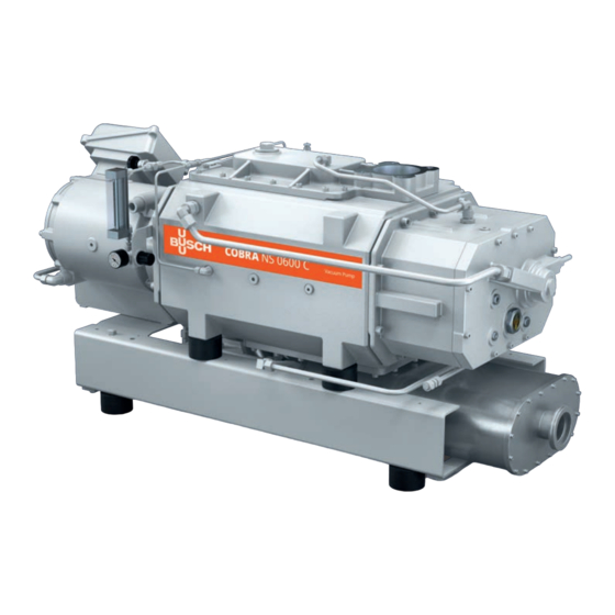
- Page 1 Instruction Manual COBRA Dry Screw Vacuum Pumps NS 0600 C 0870570426/A0006_en / Original instructions / Modifications reserved 16/06/2021...
-
Page 2: Table Of Contents
Table of Contents Table of Contents 1 Safety ............................4 2 Product Description ........................5 2.1 Operating Principle ......................6 2.2 Application........................6 2.3 Start Controls ........................6 2.4 Standard Features ......................7 2.4.1 Water Cooling ....................... 7 2.4.2 Resistance Thermometer (TSA) ................7 2.4.3 Sealing Systems ..................... - Page 3 Table of Contents 14 Oil ............................34 15 EU Declaration of Conformity....................35 0870570426_NS0600C_A0006_IM_en...
-
Page 4: Safety
Safety Prior to handling the machine, this instruction manual should be read and understood. If anything needs to be clarified, please contact your Busch representative. Read this manual carefully before use and keep for future reference. This instruction manual remains valid as long as the customer does not change anything on the product. -
Page 5: Product Description
Product Description | 2 Product Description Helium Version ODP, MP Plate heat exchanger Cooling liquid drain plug Cooling liquid fill plug Cooling liquid pump Cooling liquid vent plug Eye bolt Cooling water inlet Cooling water outlet Suction connection Magnetic plug Motor terminal box Nameplate Oil drain plug... -
Page 6: Operating Principle
Conveying of other media leads to an increased thermal and/or mechanical load on the machine and is permissible only after a consultation with Busch. The machine is intended for the placement in a non-potentially explosive environment. For suction of up to 100% of helium gas, a specific machine execution is available. This Helium Version can be identified on the pump nameplate, code “L”... -
Page 7: Standard Features
Product Description | 2 2.4 Standard Features 2.4.1 Water Cooling The machine is cooled by a cooling liquid circuit in the cylinder cover and cylinder. The cooling liquid pump (CLP) allows a recirculating flow in the cooling liquid chamber. The cooling liquid is cooled by a plate heat exchanger (PHE) which must be connected to the water main. -
Page 8: Transport
3 | Transport Transport WARNING Suspended load. Risk of severe injury! • Do not walk, stand or work under suspended loads. WARNING Lifting the machine using the motor eye bolt. Risk of severe injury! • Do not lift the machine using the eye bolt fitted to the motor. Only lift the machine as shown. -
Page 9: Storage
• Make sure that the line size of the connection lines over the entire length is at least as large as the connections of the machine. In case of long connection lines it is advisable to use larger line sizes in order to avoid a loss of efficiency. Seek advice from your Busch representative. 0870570426_NS0600C_A0006_IM_en 9 / 36... -
Page 10: Suction Connection
– DN100 ISO-K, DIN 28404 or DN100 ISO-F, DIN 28404 If the machine is used as part of a vacuum system: • Busch recommends the installation of an isolation valve in order to prevent the machine from turning backwards. 5.2.2 Discharge Connection... -
Page 11: Cooling Water Connection
Installation | 5 5.2.3 Cooling Water Connection Standard version Cooling water inlet Cooling water outlet Plate heat exchanger Helium version Cooling water inlet Cooling water outlet Plate heat exchanger • Connect the cooling water connections (CWI / CWO) to the water supply. Connection size: –... - Page 12 5 | Installation • To reduce the maintenance effort and ensure a long product lifetime we recommend the following cooling water quality: Hardness mg/l (ppm) < 90 Properties Clean & clear PH value 7 ... 9 Particle size µm < 200 Chloride mg/l <...
-
Page 13: Barrier Gas System Connection (Optional)
Installation | 5 5.2.4 Barrier Gas System Connection (Optional) Without nitrogen panel Barrier gas connection Flow meter Flow regulator Manometer Pressure regulating valve With nitrogen panel FME, FS Barrier gas connection Flow meter Flow switch Manometer Solenoid valve Nitrogen panel Pressure regulating valve •... -
Page 14: Dilution Gas System Connection (Optional)
5 | Installation Version with nitrogen panel: • Electrically connect the solenoid valve (MV), see Wiring Diagram Solenoid Valve [► 20]. • Electrically connect the flow switch (FS) of the flow meter, see Wiring Diagram Flow Switch. • Make sure that the gas complies with the following requirements: Gas type Dry nitrogen or air Gas temperature... -
Page 15: Filling Oil
Installation | 5 • Make sure that the gas complies with the following requirements: Gas type Dry nitrogen Gas temperature °C 0 ... 60 Maximum gas pressure Recommended pressure setting at the pressure regulating valve (PRV) Filtration µm Recommended flow rate SLM* * standard litre per minute 5.3 Filling Oil... - Page 16 Last oil change __ / __ / ____ Oil type see nameplate Change interval see instruction manual If there is no sticker (part no. 0565 568 959) on the machine: • Order it from your Busch representative. 16 / 36 0870570426_NS0600C_A0006_IM_en...
-
Page 17: Filling Cooling Liquid
Installation | 5 5.4 Filling Cooling Liquid For cooling liquid type and cooling liquid capacity see Technical Data [► 33] and Cooling Liquid [► 33]. Fill up to the top of the vent orifice 0870570426_NS0600C_A0006_IM_en 17 / 36... -
Page 18: Electrical Connection
• Provide an overload protection according to EN 60204-1 for the motor. • Make sure that the motor of the machine will not be affected by electric or electro- magnetic disturbance from the mains; if necessary seek advice from Busch. • Connect the protective earth conductor. -
Page 19: Wiring Diagram Three-Phase Motor (Pump Drive)
Installation | 5 5.5.1 Wiring Diagram Three-Phase Motor (Pump Drive) Motor connectors: Connection of motor temperature switches (recommended): MTS1 MTS2 MTS3 Control voltage: ≤ 250 V Max current: 1.6 A MTS = Motor temperature switch (in mo- tor coil) Double star connection (low voltage): Star connection (high voltage): NOTICE Incorrect direction of rotation. -
Page 20: Wiring Diagram Solenoid Valve (Optional)
2 (-) 5.6 Electrical Connection of the Monitoring Devices NOTE In order to prevent potential nuisance alarms, Busch recommends that the control system is configured with a time delay of at least 20 seconds. 5.6.1 Wiring Diagram Resistance Thermometer Part no.: Wiring without transmitter: PT100 : 0651 543 954... -
Page 21: Conveying Condensable Vapours
Commissioning | 6 NOTICE Lubricating a dry running machine (compression chamber). Risk of damage to the machine! • Do not lubricate the compression chamber of the machine with oil or grease. CAUTION During operation the surface of the machine may reach temperatures of more than 70°C. -
Page 22: Maintenance
Risk of injuries! Risk of premature failure and loss of efficiency! • Respect the maintenance intervals or ask your Busch representative for service. • Shut down the machine and lock against inadvertent start up. • Turn off the water supply. -
Page 23: Maintenance Schedule
• Check the cooling liquid level, see Cooling Liquid Level Inspection [► 24]. • Check the machine for oil leaks - in case of leaks have the machine repaired (contact Busch). Yearly • Carry out a visual inspection and clean the machine from dust and dirt. -
Page 24: Oil Colour Inspection
If the oil becomes dark or looks different from the initial colour: • Change the oil immediately, see Oil Change [► 25]. You can consult your Busch representative in order to find out why this colour change has occurred. 7.4 Cooling Liquid Level Inspection •... -
Page 25: Oil Change
NOTICE Use of an inappropriate oil. Risk of premature failure! Loss of efficiency! • Only use an oil type which has previously been approved and recommended by Busch. Oil draining at the motor side Cleaning cloth Magnetic plug Magnetic plug... - Page 26 7 | Maintenance Oil draining at the suction side Magnetic plug Cleaning cloth Drain pan For oil type and oil capacity see Technical Data [► 33] and Oil [► 34]. Oil filling at the motor side Check oil level 26 / 36 0870570426_NS0600C_A0006_IM_en...
- Page 27 Last oil change __ / __ / ____ Oil type see nameplate Change interval see instruction manual If there is no sticker (part no. 0565 568 959) on the machine: • Order it from your Busch representative. 0870570426_NS0600C_A0006_IM_en 27 / 36...
-
Page 28: Cooling Liquid Change
7 | Maintenance 7.6 Cooling Liquid Change For cooling liquid type and cooling liquid capacity see Technical Data [► 33] and Cooling Liquid [► 33]. Fill up to the top of the vent orifice 28 / 36 0870570426_NS0600C_A0006_IM_en... -
Page 29: Overhaul
• Decontaminate the machine as much as possible and state the contamination status in a ‘Declaration of Contamination’. Busch will only accept machines that come with a completely filled in and legally binding signed ‘Declaration of Contamination’ (form downloadable from www.buschvacuum.com). -
Page 30: Spare Parts
• The exclusive use of Busch genuine spare parts and consumables is recommended for the correct functioning of the machine and to validate the warranty. There is no standard spare parts kits available for this product, if you require Busch gen- uine parts: •... - Page 31 Busch). Solid foreign matter has • Remove the solid foreign entered the machine. matter or repair the ma- chine (contact Busch). • Install an inlet filter if ne- cessary. A temperature sensor has • Let the machine cool reached the switch point.
- Page 32 Oil Change [► 25]. The machine runs too hot. • See problem "The ma- chine runs too hot". For the solution of problems not mentioned in the troubleshooting chart contact your Busch representative. 32 / 36 0870570426_NS0600C_A0006_IM_en...
-
Page 33: Technical Data
Technical Data | 12 12 Technical Data NS 0600 C NS 0600 C (Standard version) (Helium version) Pumping speed m³/h 600 / 600 350 / 350 (50Hz / 60Hz) 353 / 353 206 / 206 Ultimate pressure (without gas bal- hPa (mbar) abs. - Page 34 14 | Oil 14 Oil VE 101 ISO-VG Part number 1 L packaging 0831 000 099 Part number 5 L packaging 0831 000 100 YLC 250 B Part number 0.5 L packaging (~1 kg) 0831 131 400 Part number 1.0 L packaging (~2 kg) 0831 108 878 Part number 5.0 L packaging (~10 kg) 0831 108 879...
- Page 35 This Declaration of Conformity and the CE-mark affixed to the nameplate are valid for the machine within the Busch scope of delivery. This Declaration of Conformity is issued under the sole responsibility of the manufacturer. When this machine is integrated into a superordinate machinery the manufacturer of the superordinate machinery (this can be the operating company, too) must conduct the conformity assessment process for the superordinate machine or plant, issue the Declaration of Conformity for it and affix the CE-mark.
- Page 36 Busch Vacuum Solutions We shape vacuum for you. Argentina Denmark Malaysia South Africa info@busch.com.ar info@busch.dk busch@busch.com.my info@busch.co.za Australia Finland Mexico Spain sales@busch.com.au info@busch.fi info@busch.com.mx contacto@buschiberica.es Austria France Netherlands Sweden busch@busch.at busch@busch.fr info@busch.nl info@busch.se Bangladesh Germany New Zealand Switzerland sales@busch.com.bd info@busch.de sales@busch.co.nz...
Need help?
Do you have a question about the COBRA and is the answer not in the manual?
Questions and answers