
Subscribe to Our Youtube Channel
Related Manuals for iDataLink maestro mus1


Summary of Contents for iDataLink maestro mus1
- Page 5 SELECT VEHICLE PRINT PAGES NEEDED HOW TO USE THIS INSTALL GUIDE Open the Bookmarks menu and find your vehicle OR scroll down until you find the install guide for your vehicle. Print only the pages for your vehicle using the advanced options in the Print menu.
- Page 6 Base RETAINS STEERING WHEEL CONTROLS, SYNC COMMANDS, SYNC BLUETOOTH, AND MORE! PRODUCTS REQUIRED OPTIONAL ACCESSORIES iDatalink Maestro RR Radio Replacement Interface Click here for: iDatalink Maestro MUS1 Dash Kit Radar Installation Guides E L E C T R O N I C S...
- Page 7 Ford Mustang Base 2010-2012 WELCOME TABLE OF CONTENTS Installation Instructions Congratulations on the purchase of your iDatalink Maestro RR Radio replacement solution. You are Wiring Diagram now a few simple steps away from enjoying your new car radio with Radio Wire Reference Chart enhanced features.
- Page 8 OK button. Once the SWI 2 wire is located and tested, go to the next step. A / C Fig. 1.1 Fig. 1.2 Fig. 2.1 Fig. 2.2 Fig. 1.3 Fig. 1.4 Fig. 2.3 Fig. 2.4 Fig. 2.5 Automotive Data Solutions Inc. © 2019 ADS-RR(SR)-MUS01-DS-IG-EN maestro.idatalink.com...
- Page 9 Fig. 3.1 Fig. 3.2 radio. • Insert the Audio cable into the iDatalink 3.5 mm audio jack of the aftermarket radio (If there is no iDatalink audio input, connect to AUX). Note: On Pioneer radio, ensure that there is nothing plugged into the W/R port.
- Page 10 STEP 10 STEERING SYNC BLUE/ORANGE WHEEL SIDE MODULE SIDE STEP 6 FACTORY RADIO HARNESS STEP 9 STEP 7 OBDII CONNECTOR MAESTRO RR MODULE MUS1 T-HARNESS CONNECTION NOT REQUIRED STEERING WHEEL CONTROL CABLE Automotive Data Solutions Inc. © 2019 ADS-RR(SR)-MUS01-DS-IG-EN maestro.idatalink.com...
- Page 11 Reverse Light Purple/White Orange/White Purple/White Purple/White Purple/White E-Brake Lt Green Yellow/Blue Lt Green Lt Green Lt Green Foot Brake Yellow/Black Yellow/Black N⁄A N⁄A VSS (vehicle speed sensor) (DATA) Pink Green/White Pink Pink Automotive Data Solutions Inc. © 2019 ADS-RR(SR)-MUS01-DS-IG-EN maestro.idatalink.com...
- Page 12 Phone: 1-866-427-2999 Email: maestro.support@idatalink.com Web: maestro.idatalink.com/support add www.12voltdata.com/forum/ IMPORTANT: To ensure proper operation, the aftermarket radio needs to have the latest fi rmware from the manufacturer. Please visit the radio manufacturer’s website and look for any updates pertaining to your radio.
- Page 13 500 & 1000 RETAINS STEERING WHEEL CONTROLS, SYNC COMMANDS, SYNC BLUETOOTH, AND MORE! PRODUCTS REQUIRED OPTIONAL ACCESSORIES iDatalink Maestro RR Radio Replacement Interface Click here for: iDatalink Maestro MUS1 Dash Kit Radar Installation Guides E L E C T R O N I C S...
- Page 14 Ford Mustang shaker 500 & 1000 2010-2012 WELCOME TABLE OF CONTENTS Installation Instructions Congratulations on the purchase of your iDatalink Maestro RR Radio replacement solution. You are Wiring Diagram now a few simple steps away from enjoying your new car radio with Radio Wire Reference Chart enhanced features.
- Page 15 OK button. Once the SWI 2 wire is located and tested, go to the next step. A / C Fig. 1.1 Fig. 1.2 Fig. 2.1 Fig. 2.2 Fig. 1.3 Fig. 1.4 Fig. 2.3 Fig. 2.4 Fig. 2.5 Automotive Data Solutions Inc. © 2019 ADS-RR(SR)-MUS01-DS-IG-EN maestro.idatalink.com...
- Page 16 Fig. 3.1 Fig. 3.2 radio. • Insert the Audio cable into the iDatalink 3.5 mm audio jack of the aftermarket radio (If there is no iDatalink audio input, connect to AUX). Note: On Pioneer radio, ensure that there is nothing plugged into the W/R port.
- Page 17 STEP 10 STEERING SYNC BLUE/ORANGE WHEEL SIDE MODULE SIDE STEP 6 FACTORY RADIO HARNESS STEP 9 STEP 7 OBDII CONNECTOR MAESTRO RR MODULE MUS1 T-HARNESS CONNECTION NOT REQUIRED STEERING WHEEL CONTROL CABLE Automotive Data Solutions Inc. © 2019 ADS-RR(SR)-MUS01-DS-IG-EN maestro.idatalink.com...
- Page 18 Reverse Light Purple/White Orange/White Purple/White Purple/White Purple/White E-Brake Lt Green Yellow/Blue Lt Green Lt Green Lt Green Foot Brake Yellow/Black Yellow/Black N⁄A N⁄A VSS (vehicle speed sensor) (DATA) Pink Green/White Pink Pink Automotive Data Solutions Inc. © 2019 ADS-RR(SR)-MUS01-DS-IG-EN maestro.idatalink.com...
- Page 19 Phone: 1-866-427-2999 Email: maestro.support@idatalink.com Web: maestro.idatalink.com/support add www.12voltdata.com/forum/ IMPORTANT: To ensure proper operation, the aftermarket radio needs to have the latest fi rmware from the manufacturer. Please visit the radio manufacturer’s website and look for any updates pertaining to your radio.
- Page 20 Base RETAINS STEERING WHEEL CONTROLS, SYNC COMMANDS, SYNC BLUETOOTH, AND MORE! PRODUCTS REQUIRED OPTIONAL ACCESSORIES iDatalink Maestro RR Radio Replacement Interface Click here for: iDatalink Maestro MUS1 Dash Kit Radar Installation Guides E L E C T R O N I C S...
- Page 21 Ford Mustang Base 2013-2014 WELCOME TABLE OF CONTENTS Installation Instructions Congratulations on the purchase of your iDatalink Maestro RR Radio replacement solution. You are Wiring Diagram now a few simple steps away from enjoying your new car radio with Radio Wire Reference Chart enhanced features.
- Page 22 OK button. Once the SWI 2 wire is located and tested, go to the next step. A / C Fig. 1.1 Fig. 1.2 Fig. 2.1 Fig. 2.2 Fig. 1.3 Fig. 1.4 Fig. 2.3 Fig. 2.4 Fig. 2.5 Automotive Data Solutions Inc. © 2019 ADS-RR(SR)-MUS01-DS-IG-EN maestro.idatalink.com...
- Page 23 Fig. 3.1 Fig. 3.2 radio. • Insert the Audio cable into the iDatalink 3.5 mm audio jack of the aftermarket radio (If there is no iDatalink audio input, connect to AUX). Note: On Pioneer radio, ensure that there is nothing plugged into the W/R port.
- Page 24 STEP 10 STEERING SYNC BLUE WHEEL SIDE MODULE SIDE STEP 6 FACTORY RADIO HARNESS STEP 9 STEP 7 OBDII CONNECTOR MAESTRO RR MODULE MUS1 T-HARNESS CONNECTION NOT REQUIRED STEERING WHEEL CONTROL CABLE Automotive Data Solutions Inc. © 2019 ADS-RR(SR)-MUS01-DS-IG-EN maestro.idatalink.com...
- Page 25 Reverse Light Purple/White Orange/White Purple/White Purple/White Purple/White E-Brake Lt Green Yellow/Blue Lt Green Lt Green Lt Green Foot Brake Yellow/Black Yellow/Black N⁄A N⁄A VSS (vehicle speed sensor) (DATA) Pink Green/White Pink Pink Automotive Data Solutions Inc. © 2019 ADS-RR(SR)-MUS01-DS-IG-EN maestro.idatalink.com...
- Page 26 Phone: 1-866-427-2999 Email: maestro.support@idatalink.com Web: maestro.idatalink.com/support add www.12voltdata.com/forum/ IMPORTANT: To ensure proper operation, the aftermarket radio needs to have the latest fi rmware from the manufacturer. Please visit the radio manufacturer’s website and look for any updates pertaining to your radio.
- Page 27 RETAINS STEERING WHEEL CONTROLS, SYNC COMMANDS, SYNC BLUETOOTH, AND MORE! PRODUCTS REQUIRED OPTIONAL ACCESSORIES iDatalink Maestro RR Radio Replacement Interface Click here for: iDatalink Maestro MUS1 Dash Kit Radar Installation Guides E L E C T R O N I C S...
- Page 28 Ford Mustang shaker 2013-2014 WELCOME TABLE OF CONTENTS Installation Instructions Congratulations on the purchase of your iDatalink Maestro RR Radio replacement solution. You are Wiring Diagram now a few simple steps away from enjoying your new car radio with Radio Wire Reference Chart enhanced features.
- Page 29 OK button. Once the SWI 2 wire is located and tested, go to the next step. A / C Fig. 1.1 Fig. 1.2 Fig. 2.1 Fig. 2.2 Fig. 1.3 Fig. 1.4 Fig. 2.3 Fig. 2.4 Fig. 2.5 Automotive Data Solutions Inc. © 2019 ADS-RR(SR)-MUS01-DS-IG-EN maestro.idatalink.com...
- Page 30 Fig. 3.1 Fig. 3.2 radio. • Insert the Audio cable into the iDatalink 3.5 mm audio jack of the aftermarket radio (If there is no iDatalink audio input, connect to AUX). Note: On Pioneer radio, ensure that there is nothing plugged into the W/R port.
- Page 31 STEP 10 STEERING SYNC BLUE WHEEL SIDE MODULE SIDE STEP 6 FACTORY RADIO HARNESS STEP 9 STEP 7 OBDII CONNECTOR MAESTRO RR MODULE MUS1 T-HARNESS CONNECTION NOT REQUIRED STEERING WHEEL CONTROL CABLE Automotive Data Solutions Inc. © 2019 ADS-RR(SR)-MUS01-DS-IG-EN maestro.idatalink.com...
- Page 32 Reverse Light Purple/White Orange/White Purple/White Purple/White Purple/White E-Brake Lt Green Yellow/Blue Lt Green Lt Green Lt Green Foot Brake Yellow/Black Yellow/Black N⁄A N⁄A VSS (vehicle speed sensor) (DATA) Pink Green/White Pink Pink Automotive Data Solutions Inc. © 2019 ADS-RR(SR)-MUS01-DS-IG-EN maestro.idatalink.com...
- Page 33 Phone: 1-866-427-2999 Email: maestro.support@idatalink.com Web: maestro.idatalink.com/support add www.12voltdata.com/forum/ IMPORTANT: To ensure proper operation, the aftermarket radio needs to have the latest fi rmware from the manufacturer. Please visit the radio manufacturer’s website and look for any updates pertaining to your radio.
- Page 34 Pro RETAINS STEERING WHEEL CONTROLS, SYNC COMMANDS, SYNC BLUETOOTH, AND MORE! PRODUCTS REQUIRED OPTIONAL ACCESSORIES iDatalink Maestro RR Radio Replacement Interface Click here for: iDatalink Maestro MUS1 Dash Kit Radar Installation Guides E L E C T R O N I C S...
- Page 35 Ford Mustang shaker Pro 2013-2014 WELCOME TABLE OF CONTENTS Installation Instructions Congratulations on the purchase of your iDatalink Maestro RR Radio replacement solution. You are Wiring Diagram now a few simple steps away from enjoying your new car radio with Radio Wire Reference Chart enhanced features.
- Page 36 OK button. Once the SWI 2 wire is located and tested, go to the next step. A / C Fig. 1.1 Fig. 1.2 Fig. 2.1 Fig. 2.2 Fig. 1.3 Fig. 1.4 Fig. 2.3 Fig. 2.4 Fig. 2.5 Automotive Data Solutions Inc. © 2019 ADS-RR(SR)-MUS01-DS-IG-EN maestro.idatalink.com...
- Page 37 Fig. 3.1 Fig. 3.2 radio. • Insert the Audio cable into the iDatalink 3.5 mm audio jack of the aftermarket radio (If there is no iDatalink audio input, connect to AUX). Note: On Pioneer radio, ensure that there is nothing plugged into the W/R port.
- Page 38 STEP 10 STEERING SYNC BLUE WHEEL SIDE MODULE SIDE STEP 6 FACTORY RADIO HARNESS STEP 9 STEP 7 OBDII CONNECTOR MAESTRO RR MODULE MUS1 T-HARNESS CONNECTION NOT REQUIRED STEERING WHEEL CONTROL CABLE Automotive Data Solutions Inc. © 2019 ADS-RR(SR)-MUS01-DS-IG-EN maestro.idatalink.com...
- Page 39 Reverse Light Purple/White Orange/White Purple/White Purple/White Purple/White E-Brake Lt Green Yellow/Blue Lt Green Lt Green Lt Green Foot Brake Yellow/Black Yellow/Black N⁄A N⁄A VSS (vehicle speed sensor) (DATA) Pink Green/White Pink Pink Automotive Data Solutions Inc. © 2019 ADS-RR(SR)-MUS01-DS-IG-EN maestro.idatalink.com...
- Page 40 Phone: 1-866-427-2999 Email: maestro.support@idatalink.com Web: maestro.idatalink.com/support add www.12voltdata.com/forum/ IMPORTANT: To ensure proper operation, the aftermarket radio needs to have the latest fi rmware from the manufacturer. Please visit the radio manufacturer’s website and look for any updates pertaining to your radio.
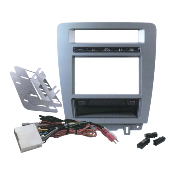
- Page 41 KIT-MUS1 Button Bar Rework Procedure 1. Issue: The backlight of “CLIMATE” button is not evenly distributed. 2. Rework procedure: a. Remove 4 screws. b. Use a small flat screwdriver slightly press on the lock tabs to release the back cover. Remove the back cover. c.
- Page 42 d. Cut the rubber which is marked “X”...
- Page 43 e. Position the rubber pad back on the PCB after cutting and removing the small piece of rubber. f. Assemble the button bar in reverse from step 2C.
Need help?
Do you have a question about the maestro mus1 and is the answer not in the manual?
Questions and answers