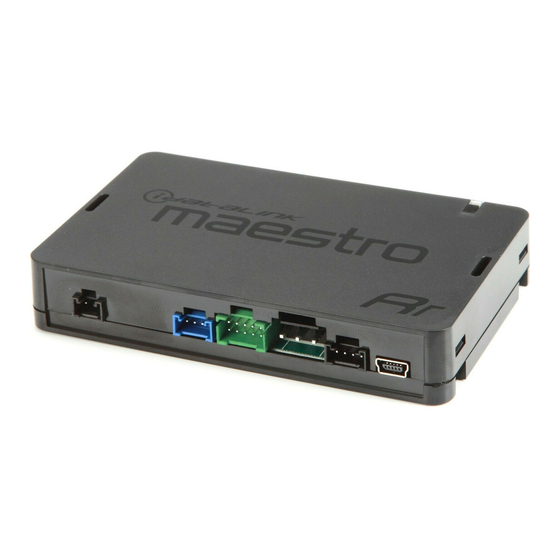
iDataLink maestro Rr Install Manual
Hide thumbs
Also See for maestro Rr:
- Install manual (1403 pages) ,
- How to use manual (201 pages) ,
- Manual (106 pages)
Advertisement
Quick Links
SELECT VEHICLE
PRINT PAGES NEEDED
HOW TO USE THIS INSTALL GUIDE
1
Open the Bookmarks menu and find your vehicle OR scroll
down until you find the install guide for your vehicle.
2
Print only the pages for your vehicle using the advanced
options in the Print menu.
3
Install your Maestro RR according to the guide for your vehicle.
Pressing the printer icon or "quick printing" this document will print
NOTICE: Automotive Data Solutions Inc. (ADS) recommends having this installation performed by a certifi ed technician. Logos and trademarks used here in
are the properties of their respective owners.
WARNING
all of the guides in this compilation.
Advertisement

Subscribe to Our Youtube Channel
Related Manuals for iDataLink maestro Rr


Summary of Contents for iDataLink maestro Rr
- Page 1 Print only the pages for your vehicle using the advanced options in the Print menu. Install your Maestro RR according to the guide for your vehicle. WARNING Pressing the printer icon or “quick printing” this document will print all of the guides in this compilation.
- Page 2 Jeep Wrangler Jl With 5" radio RETAINS STEERING WHEEL CONTROLS AND MORE! PRODUCTS REQUIRED ACCESSORIES ACC-SP1 iDatalink Maestro RR or RR2 Radio Replacement Interface iDatalink Maestro CH3 Installation Harness PROGRAMMED FIRMWARE ADS-RR(SR)-CHR03-AS ADDITIONAL RESOURCES Maestro RR2 Programmable Outputs Guide NOTICE: Automotive Data Solutions Inc. (ADS) recommends having this installation performed by a certified technician. Logos and trademarks used here...
- Page 3 Jeep Wrangler Jl With 5" radio 2018-2023 WELCOME TABLE OF CONTENTS Installation Instructions Congratulations on the purchase of your iDatalink Maestro RR Radio replacement solution. You are Wiring Diagram now a few simple steps away from enjoying your new car radio with Radio Wire Reference Chart enhanced features.
- Page 4 (ex: Alpine). • Connect all the harnesses to the Maestro RR module then If the vehicle DOES NOT have a factory amplifi er: test your installation.
- Page 5 LOCATION: BEHIND GLOVE BOX HARNESS INTO THE JUNCTION BLOCK. CONNECT THE FACTORY 2 PIN CONNECTOR INTO THE EXTENSION HARNESS FEMALE WHITE 2-PIN CONNECTOR. NOTE: DO NOT CUT VEHICLE WIRES MAESTRO RR MODULE HARNESS VERSION 1.6 - YELLOW/BROWN RED/BROWN BLACK CAN JUNCTION CONNECTOR...
- Page 6 Reverse Light Purple/White Orange/White Purple/White Purple/White Purple/White E-Brake Lt Green Yellow/Blue Lt Green Lt Green Lt Green Foot Brake Yellow/Black Yellow/Black N⁄A N⁄A VSS (vehicle speed sensor) (DATA) Pink Green/White Pink Pink Automotive Data Solutions Inc. © 2023 ADS-RR(SR)-CHR03-AS-IG-EN maestro.idatalink.com...
- Page 7 Turns off after one minute: Normal operation. • • Normal operation (inactive). VIDEO HELP Installation, product information, vehicle specific videos. VERIFY FLASH Last flash information, steering control configuration, vehicle information. WEBLINK Software to program module. Automotive Data Solutions Inc. © 2023 ADS-RR(SR)-CHR03-AS-IG-EN maestro.idatalink.com...
- Page 8 The radio stays ON. Make sure the 2-pin connectors in the harness are connected as stated in step 2. MAESTRO RR RESET PROCEDURE: Turn the key to the OFF position, then disconnect all connectors from the module. Press and hold the module’s programming button and connect all the connectors back to the module. Wait, the module’s LED will fl ash RED rapidly (this may take up to 10 seconds).
- Page 9 Ram 1500 ClassiC with 3" oR 5" Radio RETAINS STEERING WHEEL CONTROLS AND MORE! PRODUCTS REQUIRED ACCESSORIES ACC-SP1 iDatalink Maestro RR or RR2 Radio Replacement Interface iDatalink Maestro CH3 Installation Harness PROGRAMMED FIRMWARE ADS-RR(SR)-CHR03-AS ADDITIONAL RESOURCES Maestro RR2 Programmable Outputs Guide NOTICE: Automotive Data Solutions Inc.
- Page 10 Ram 1500 ClassiC with 3" oR 5" Radio 2019-2023 WELCOME TABLE OF CONTENTS Installation Instructions Congratulations on the purchase of your iDatalink Maestro RR Radio replacement solution. You are Wiring Diagram now a few simple steps away from enjoying your new car radio with Radio Wire Reference Chart enhanced features.
- Page 11 (ex: Alpine). If the vehicle DOES NOT have a factory amplifi er: • Connect all the harnesses to the Maestro RR module then test your installation. • Plug the female GREEN connector to the male GREEN connector of your CH3 T-harness.
- Page 12 LOCATION: DRIVER SIDE DASH HARNESS INTO THE JUNCTION BLOCK. CONNECT THE FACTORY 2 PIN CONNECTOR INTO THE EXTENSION HARNESS FEMALE WHITE 2-PIN CONNECTOR. NOTE: DO NOT CUT VEHICLE WIRES MAESTRO RR MODULE HARNESS VERSION 1.6 - YELLOW/BROWN RED/BROWN BLACK CAN JUNCTION CONNECTOR...
- Page 13 Reverse Light Purple/White Orange/White Purple/White Purple/White Purple/White E-Brake Lt Green Yellow/Blue Lt Green Lt Green Lt Green Foot Brake Yellow/Black Yellow/Black N⁄A N⁄A VSS (vehicle speed sensor) (DATA) Pink Green/White Pink Pink Automotive Data Solutions Inc. © 2023 ADS-RR(SR)-CHR03-AS-IG-EN maestro.idatalink.com...
- Page 14 Turns off after one minute: Normal operation. • • Normal operation (inactive). VIDEO HELP Installation, product information, vehicle specific videos. VERIFY FLASH Last flash information, steering control configuration, vehicle information. WEBLINK Software to program module. Automotive Data Solutions Inc. © 2023 ADS-RR(SR)-CHR03-AS-IG-EN maestro.idatalink.com...
- Page 15 The radio stays ON. Make sure the 2-pin connectors in the harness are connected as stated in step 2. MAESTRO RR RESET PROCEDURE: Turn the key to the OFF position, then disconnect all connectors from the module. Press and hold the module’s programming button and connect all the connectors back to the module. Wait, the module’s LED will fl ash RED rapidly (this may take up to 10 seconds).
- Page 16 Ram 1500 with 3" oR 5" Radio RETAINS STEERING WHEEL CONTROLS AND MORE! PRODUCTS REQUIRED ACCESSORIES ACC-SP1 iDatalink Maestro RR or RR2 Radio Replacement Interface iDatalink Maestro CH3 Installation Harness PROGRAMMED FIRMWARE ADS-RR(SR)-CHR03-AS ADDITIONAL RESOURCES Maestro RR2 Programmable Outputs Guide NOTICE: Automotive Data Solutions Inc.
- Page 17 Ram 1500 with 3" oR 5" Radio 2013-2017 WELCOME TABLE OF CONTENTS Installation Instructions Congratulations on the purchase of your iDatalink Maestro RR Radio replacement solution. You are Wiring Diagram now a few simple steps away from enjoying your new car radio with Radio Wire Reference Chart enhanced features.
- Page 18 OEM settings menus. To retain the OEM settings menus, you must use an iDatalink compatible radio. • Connect all the harnesses to the Maestro RR module then test your installation. • If the vehicle is equipped with OEM parking assist and no...
- Page 19 WHITE WHITE N.C. STEP 5 WHITE WHITE SPEAKER* *REQUIRED ACCESSORY BLACK BLACK In vehicles without OEM amplifier, with OEM parking sensors MAESTRO RR MODULE CH3 T-HARNESS NOT REQUIRED DATA CABLE AUDIO CABLE Automotive Data Solutions Inc. © 2023 ADS-RR(SR)-CHR03-AS-IG-EN maestro.idatalink.com...
- Page 20 Reverse Light Purple/White Orange/White Purple/White Purple/White Purple/White E-Brake Lt Green Yellow/Blue Lt Green Lt Green Lt Green Foot Brake Yellow/Black Yellow/Black N⁄A N⁄A VSS (vehicle speed sensor) (DATA) Pink Green/White Pink Pink Automotive Data Solutions Inc. © 2023 ADS-RR(SR)-CHR03-AS-IG-EN maestro.idatalink.com...
- Page 21 Turns off after one minute: Normal operation. • • Normal operation (inactive). VIDEO HELP Installation, product information, vehicle specific videos. VERIFY FLASH Last flash information, steering control configuration, vehicle information. WEBLINK Software to program module. Automotive Data Solutions Inc. © 2023 ADS-RR(SR)-CHR03-AS-IG-EN maestro.idatalink.com...
- Page 22 The radio stays ON. Make sure the 2-pin connectors in the harness are connected as stated in step 2. MAESTRO RR RESET PROCEDURE: Turn the key to the OFF position, then disconnect all connectors from the module. Press and hold the module’s programming button and connect all the connectors back to the module. Wait, the module’s LED will fl ash RED rapidly (this may take up to 10 seconds).
- Page 23 Ram 1500 with 3" oR 5" Radio RETAINS STEERING WHEEL CONTROLS AND MORE! PRODUCTS REQUIRED ACCESSORIES ACC-SP1 iDatalink Maestro RR or RR2 Radio Replacement Interface iDatalink Maestro CH3 Installation Harness PROGRAMMED FIRMWARE ADS-RR(SR)-CHR03-AS ADDITIONAL RESOURCES Maestro RR2 Programmable Outputs Guide NOTICE: Automotive Data Solutions Inc.
- Page 24 Ram 1500 with 3" oR 5" Radio 2018 WELCOME TABLE OF CONTENTS Installation Instructions Congratulations on the purchase of your iDatalink Maestro RR Radio replacement solution. You are Wiring Diagram now a few simple steps away from enjoying your new car radio with Radio Wire Reference Chart enhanced features.
- Page 25 (ex: Alpine). If the vehicle DOES NOT have a factory amplifi er: • Connect all the harnesses to the Maestro RR module then test your installation. • Plug the female GREEN connector to the male GREEN connector of your CH3 T-harness.
- Page 26 LOCATION: DRIVER SIDE DASH HARNESS INTO THE JUNCTION BLOCK. CONNECT THE FACTORY 2 PIN CONNECTOR INTO THE EXTENSION HARNESS FEMALE WHITE 2-PIN CONNECTOR. NOTE: DO NOT CUT VEHICLE WIRES MAESTRO RR MODULE HARNESS VERSION 1.6 - YELLOW/BROWN RED/BROWN BLACK CAN JUNCTION CONNECTOR...
- Page 27 Reverse Light Purple/White Orange/White Purple/White Purple/White Purple/White E-Brake Lt Green Yellow/Blue Lt Green Lt Green Lt Green Foot Brake Yellow/Black Yellow/Black N⁄A N⁄A VSS (vehicle speed sensor) (DATA) Pink Green/White Pink Pink Automotive Data Solutions Inc. © 2023 ADS-RR(SR)-CHR03-AS-IG-EN maestro.idatalink.com...
- Page 28 Turns off after one minute: Normal operation. • • Normal operation (inactive). VIDEO HELP Installation, product information, vehicle specific videos. VERIFY FLASH Last flash information, steering control configuration, vehicle information. WEBLINK Software to program module. Automotive Data Solutions Inc. © 2023 ADS-RR(SR)-CHR03-AS-IG-EN maestro.idatalink.com...
- Page 29 The radio stays ON. Make sure the 2-pin connectors in the harness are connected as stated in step 2. MAESTRO RR RESET PROCEDURE: Turn the key to the OFF position, then disconnect all connectors from the module. Press and hold the module’s programming button and connect all the connectors back to the module. Wait, the module’s LED will fl ash RED rapidly (this may take up to 10 seconds).
- Page 30 Ram 1500 with 5" Radio RETAINS STEERING WHEEL CONTROLS AND MORE! PRODUCTS REQUIRED ACCESSORIES ACC-SP1 iDatalink Maestro RR or RR2 Radio Replacement Interface iDatalink Maestro CH3 Installation Harness PROGRAMMED FIRMWARE ADS-RR(SR)-CHR03-AS ADDITIONAL RESOURCES Maestro RR2 Programmable Outputs Guide NOTICE: Automotive Data Solutions Inc. (ADS) recommends having this installation performed by a certified technician. Logos and trademarks used here...
- Page 31 Ram 1500 with 5" Radio 2019-2021 WELCOME TABLE OF CONTENTS Installation Instructions Congratulations on the purchase of your iDatalink Maestro RR Radio replacement solution. You are Wiring Diagram now a few simple steps away from enjoying your new car radio with Radio Wire Reference Chart enhanced features.
- Page 32 • Determine if the vehicle has a factory amplifi er. Look for badges on the radio, door panels and dash that indicate the • Connect all the harnesses to the Maestro RR module then presence of an amplifi er (ex: Alpine).
- Page 33 LOCATION: DRIVER SIDE DASH HARNESS INTO THE JUNCTION BLOCK. CONNECT THE FACTORY 2 PIN CONNECTOR INTO THE EXTENSION HARNESS FEMALE WHITE 2-PIN CONNECTOR. NOTE: DO NOT CUT VEHICLE WIRES MAESTRO RR MODULE HARNESS VERSION 1.6 - YELLOW/BROWN RED/BROWN BLACK CAN JUNCTION CONNECTOR...
- Page 34 Reverse Light Purple/White Orange/White Purple/White Purple/White Purple/White E-Brake Lt Green Yellow/Blue Lt Green Lt Green Lt Green Foot Brake Yellow/Black Yellow/Black N⁄A N⁄A VSS (vehicle speed sensor) (DATA) Pink Green/White Pink Pink Automotive Data Solutions Inc. © 2023 ADS-RR(SR)-CHR03-AS-IG-EN maestro.idatalink.com...
- Page 35 Turns off after one minute: Normal operation. • • Normal operation (inactive). VIDEO HELP Installation, product information, vehicle specific videos. VERIFY FLASH Last flash information, steering control configuration, vehicle information. WEBLINK Software to program module. Automotive Data Solutions Inc. © 2023 ADS-RR(SR)-CHR03-AS-IG-EN maestro.idatalink.com...
- Page 36 The radio stays ON. Make sure the 2-pin connectors in the harness are connected as stated in step 2. MAESTRO RR RESET PROCEDURE: Turn the key to the OFF position, then disconnect all connectors from the module. Press and hold the module’s programming button and connect all the connectors back to the module. Wait, the module’s LED will fl ash RED rapidly (this may take up to 10 seconds).
- Page 37 Ram 2500 & 3500 with 3" oR 5" Radio RETAINS STEERING WHEEL CONTROLS AND MORE! PRODUCTS REQUIRED ACCESSORIES ACC-SP1 iDatalink Maestro RR or RR2 Radio Replacement Interface iDatalink Maestro CH3 Installation Harness PROGRAMMED FIRMWARE ADS-RR(SR)-CHR03-AS ADDITIONAL RESOURCES Maestro RR2 Programmable Outputs Guide NOTICE: Automotive Data Solutions Inc.
- Page 38 Ram 2500 & 3500 with 3" oR 5" Radio 2013-2018 WELCOME TABLE OF CONTENTS Installation Instructions Congratulations on the purchase of your iDatalink Maestro RR Radio replacement solution. You are Wiring Diagram now a few simple steps away from enjoying your new car radio with Radio Wire Reference Chart enhanced features.
- Page 39 OEM settings menus. To retain the OEM settings menus, you must use an iDatalink compatible radio. • Connect all the harnesses to the Maestro RR module then test your installation. • If the vehicle is equipped with OEM parking assist and no...
- Page 40 WHITE WHITE N.C. STEP 5 WHITE WHITE SPEAKER* *REQUIRED ACCESSORY BLACK BLACK In vehicles without OEM amplifier, with OEM parking sensors MAESTRO RR MODULE CH3 T-HARNESS NOT REQUIRED DATA CABLE AUDIO CABLE Automotive Data Solutions Inc. © 2023 ADS-RR(SR)-CHR03-AS-IG-EN maestro.idatalink.com...
- Page 41 Reverse Light Purple/White Orange/White Purple/White Purple/White Purple/White E-Brake Lt Green Yellow/Blue Lt Green Lt Green Lt Green Foot Brake Yellow/Black Yellow/Black N⁄A N⁄A VSS (vehicle speed sensor) (DATA) Pink Green/White Pink Pink Automotive Data Solutions Inc. © 2023 ADS-RR(SR)-CHR03-AS-IG-EN maestro.idatalink.com...
- Page 42 Turns off after one minute: Normal operation. • • Normal operation (inactive). VIDEO HELP Installation, product information, vehicle specific videos. VERIFY FLASH Last flash information, steering control configuration, vehicle information. WEBLINK Software to program module. Automotive Data Solutions Inc. © 2023 ADS-RR(SR)-CHR03-AS-IG-EN maestro.idatalink.com...
- Page 43 The radio stays ON. Make sure the 2-pin connectors in the harness are connected as stated in step 2. MAESTRO RR RESET PROCEDURE: Turn the key to the OFF position, then disconnect all connectors from the module. Press and hold the module’s programming button and connect all the connectors back to the module. Wait, the module’s LED will fl ash RED rapidly (this may take up to 10 seconds).
- Page 44 Ram 2500 & 3500 with 5" Radio RETAINS STEERING WHEEL CONTROLS AND MORE! PRODUCTS REQUIRED ACCESSORIES ACC-SP1 iDatalink Maestro RR or RR2 Radio Replacement Interface iDatalink Maestro CH3 Installation Harness PROGRAMMED FIRMWARE ADS-RR(SR)-CHR03-AS ADDITIONAL RESOURCES Maestro RR2 Programmable Outputs Guide NOTICE: Automotive Data Solutions Inc.
- Page 45 Ram 2500 & 3500 with 5" Radio 2019-2021 WELCOME TABLE OF CONTENTS Installation Instructions Congratulations on the purchase of your iDatalink Maestro RR Radio replacement solution. You are Wiring Diagram now a few simple steps away from enjoying your new car radio with Radio Wire Reference Chart enhanced features.
- Page 46 • Determine if the vehicle has a factory amplifi er. Look for badges on the radio, door panels and dash that indicate the • Connect all the harnesses to the Maestro RR module then presence of an amplifi er (ex: Alpine).
- Page 47 LOCATION: DRIVER SIDE DASH HARNESS INTO THE JUNCTION BLOCK. CONNECT THE FACTORY 2 PIN CONNECTOR INTO THE EXTENSION HARNESS FEMALE WHITE 2-PIN CONNECTOR. NOTE: DO NOT CUT VEHICLE WIRES MAESTRO RR MODULE HARNESS VERSION 1.6 - YELLOW/BROWN RED/BROWN BLACK CAN JUNCTION CONNECTOR...
- Page 48 Reverse Light Purple/White Orange/White Purple/White Purple/White Purple/White E-Brake Lt Green Yellow/Blue Lt Green Lt Green Lt Green Foot Brake Yellow/Black Yellow/Black N⁄A N⁄A VSS (vehicle speed sensor) (DATA) Pink Green/White Pink Pink Automotive Data Solutions Inc. © 2023 ADS-RR(SR)-CHR03-AS-IG-EN maestro.idatalink.com...
- Page 49 Turns off after one minute: Normal operation. • • Normal operation (inactive). VIDEO HELP Installation, product information, vehicle specific videos. VERIFY FLASH Last flash information, steering control configuration, vehicle information. WEBLINK Software to program module. Automotive Data Solutions Inc. © 2023 ADS-RR(SR)-CHR03-AS-IG-EN maestro.idatalink.com...
- Page 50 The radio stays ON. Make sure the 2-pin connectors in the harness are connected as stated in step 2. MAESTRO RR RESET PROCEDURE: Turn the key to the OFF position, then disconnect all connectors from the module. Press and hold the module’s programming button and connect all the connectors back to the module. Wait, the module’s LED will fl ash RED rapidly (this may take up to 10 seconds).
- Page 51 Ram Chassis Cab with 3" oR 5" Radio RETAINS STEERING WHEEL CONTROLS AND MORE! PRODUCTS REQUIRED ACCESSORIES ACC-SP1 iDatalink Maestro RR or RR2 Radio Replacement Interface iDatalink Maestro CH3 Installation Harness PROGRAMMED FIRMWARE ADS-RR(SR)-CHR03-AS ADDITIONAL RESOURCES Maestro RR2 Programmable Outputs Guide NOTICE: Automotive Data Solutions Inc.
- Page 52 Ram Chassis Cab with 3" oR 5" Radio 2013-2018 WELCOME TABLE OF CONTENTS Installation Instructions Congratulations on the purchase of your iDatalink Maestro RR Radio replacement solution. You are Wiring Diagram now a few simple steps away from enjoying your new car radio with Radio Wire Reference Chart enhanced features.
- Page 53 OEM settings menus. To retain the OEM settings menus, you must use an iDatalink compatible radio. • Connect all the harnesses to the Maestro RR module then test your installation. • If the vehicle is equipped with OEM parking assist and no...
- Page 54 WHITE WHITE N.C. STEP 5 WHITE WHITE SPEAKER* *REQUIRED ACCESSORY BLACK BLACK In vehicles without OEM amplifier, with OEM parking sensors MAESTRO RR MODULE CH3 T-HARNESS NOT REQUIRED DATA CABLE AUDIO CABLE Automotive Data Solutions Inc. © 2023 ADS-RR(SR)-CHR03-AS-IG-EN maestro.idatalink.com...
- Page 55 Reverse Light Purple/White Orange/White Purple/White Purple/White Purple/White E-Brake Lt Green Yellow/Blue Lt Green Lt Green Lt Green Foot Brake Yellow/Black Yellow/Black N⁄A N⁄A VSS (vehicle speed sensor) (DATA) Pink Green/White Pink Pink Automotive Data Solutions Inc. © 2023 ADS-RR(SR)-CHR03-AS-IG-EN maestro.idatalink.com...
- Page 56 Turns off after one minute: Normal operation. • • Normal operation (inactive). VIDEO HELP Installation, product information, vehicle specific videos. VERIFY FLASH Last flash information, steering control configuration, vehicle information. WEBLINK Software to program module. Automotive Data Solutions Inc. © 2023 ADS-RR(SR)-CHR03-AS-IG-EN maestro.idatalink.com...
- Page 57 The radio stays ON. Make sure the 2-pin connectors in the harness are connected as stated in step 2. MAESTRO RR RESET PROCEDURE: Turn the key to the OFF position, then disconnect all connectors from the module. Press and hold the module’s programming button and connect all the connectors back to the module. Wait, the module’s LED will fl ash RED rapidly (this may take up to 10 seconds).
- Page 58 Ram Chassis Cab with 5" Radio RETAINS STEERING WHEEL CONTROLS AND MORE! PRODUCTS REQUIRED ACCESSORIES ACC-SP1 iDatalink Maestro RR or RR2 Radio Replacement Interface iDatalink Maestro CH3 Installation Harness PROGRAMMED FIRMWARE ADS-RR(SR)-CHR03-AS ADDITIONAL RESOURCES Maestro RR2 Programmable Outputs Guide NOTICE: Automotive Data Solutions Inc. (ADS) recommends having this installation performed by a certified technician. Logos and trademarks used here...
- Page 59 Ram Chassis Cab with 5" Radio 2019-2021 WELCOME TABLE OF CONTENTS Installation Instructions Congratulations on the purchase of your iDatalink Maestro RR Radio replacement solution. You are Wiring Diagram now a few simple steps away from enjoying your new car radio with Radio Wire Reference Chart enhanced features.
- Page 60 • Determine if the vehicle has a factory amplifi er. Look for badges on the radio, door panels and dash that indicate the • Connect all the harnesses to the Maestro RR module then presence of an amplifi er (ex: Alpine).
- Page 61 LOCATION: DRIVER SIDE DASH HARNESS INTO THE JUNCTION BLOCK. CONNECT THE FACTORY 2 PIN CONNECTOR INTO THE EXTENSION HARNESS FEMALE WHITE 2-PIN CONNECTOR. NOTE: DO NOT CUT VEHICLE WIRES MAESTRO RR MODULE HARNESS VERSION 1.6 - YELLOW/BROWN RED/BROWN BLACK CAN JUNCTION CONNECTOR...
- Page 62 Reverse Light Purple/White Orange/White Purple/White Purple/White Purple/White E-Brake Lt Green Yellow/Blue Lt Green Lt Green Lt Green Foot Brake Yellow/Black Yellow/Black N⁄A N⁄A VSS (vehicle speed sensor) (DATA) Pink Green/White Pink Pink Automotive Data Solutions Inc. © 2023 ADS-RR(SR)-CHR03-AS-IG-EN maestro.idatalink.com...
- Page 63 Turns off after one minute: Normal operation. • • Normal operation (inactive). VIDEO HELP Installation, product information, vehicle specific videos. VERIFY FLASH Last flash information, steering control configuration, vehicle information. WEBLINK Software to program module. Automotive Data Solutions Inc. © 2023 ADS-RR(SR)-CHR03-AS-IG-EN maestro.idatalink.com...
- Page 64 The radio stays ON. Make sure the 2-pin connectors in the harness are connected as stated in step 2. MAESTRO RR RESET PROCEDURE: Turn the key to the OFF position, then disconnect all connectors from the module. Press and hold the module’s programming button and connect all the connectors back to the module. Wait, the module’s LED will fl ash RED rapidly (this may take up to 10 seconds).
Need help?
Do you have a question about the maestro Rr and is the answer not in the manual?
Questions and answers