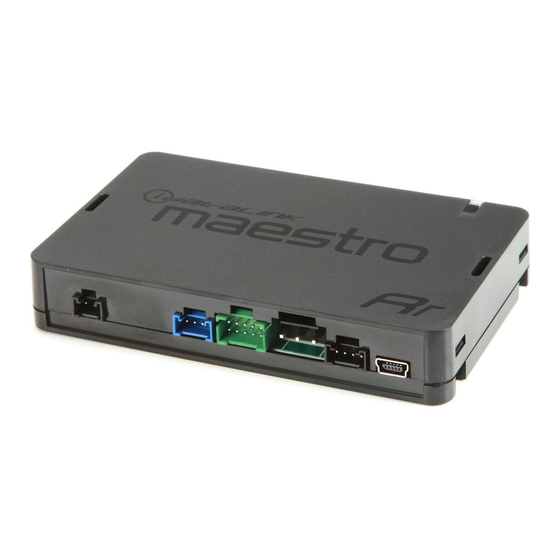
Open the Bookmarks menu and find your vehicle OR scroll
down until you find the install guide for your vehicle.
2
Print only the pages for your vehicle using the advanced
options in the Print menu.
3
Install your Maestro RR according to the guide for your vehicle.
Pressing the printer icon or "quick printing" this document will print
NOTICE: Automotive Data Solutions Inc. (ADS) recommends having this installation performed by a certifi ed technician. Logos and trademarks used here in
Page 1
Print only the pages for your vehicle using the advanced options in the Print menu. Install your Maestro RR according to the guide for your vehicle. WARNING Pressing the printer icon or “quick printing” this document will print all of the guides in this compilation.
Page 2
Chevrolet Cruze limited With Color sCreen (not retained) With amP RETAINS STEERING WHEEL CONTROLS, ONSTAR, AND MORE! PRODUCTS REQUIRED OPTIONAL ACCESSORIES iDatalink Maestro RR Radio Replacement Interface iDatalink Maestro HRR-GM2 Installation Harness PROGRAMMED FIRMWARE ADS-RR(SR)-GMS02A-AS ADDITIONAL RESOURCES Maestro RR2 Programmable Outputs Guide NOTICE: Automotive Data Solutions Inc.
Page 3
Chevrolet Cruze limited With Color sCreen (not retained) With amP 2016 WELCOME TABLE OF CONTENTS Installation Instructions Congratulations on the purchase of your iDatalink Maestro RR Radio replacement solution. You are Wiring Diagram now a few simple steps away from enjoying your new car radio with Radio Wire Reference Chart enhanced features.
CAM 2 VEHICLE STEP 3 FACTORY RADIO HARNESS STEP 5 WHITE WHITE ACC-SP1 CONNECT ONLY IF USING MAESTRO RR2 MODULE MAESTRO RR MODULE CONNECT ONLY IF USING MAESTRO RR MODULE AMP TURNON AMP TURNON HRR-GM2 T-HARNESS NOT REQUIRED DATA CABLE AUDIO...
Page 6
Wire Color on Adapter Kenwood Radio Wire Description Refer to camera/radio Green/Red manual Refer to camera/radio Green/White manual Connect if no iDatalink Steering Wheel Controls (DATA) Blue/Yellow 4-pin port on radio ACC-HU-KEN2 Polarity Wire Color on Adapter Kenwood Radio Wire Description...
Page 8
Ensure the 2-pin yellow plug is connected as shown on the diagram. reverse. MAESTRO RR RESET PROCEDURE: Turn the key to the OFF position, then disconnect all connectors from the module. Press and hold the module’s programming button and connect all the connectors back to the module. Wait, the module’s LED will fl ash RED rapidly (this may take up to 10 seconds).
Page 9
Chevrolet Cruze limited With Color sCreen (not retained) Without amP RETAINS STEERING WHEEL CONTROLS, ONSTAR, AND MORE! PRODUCTS REQUIRED OPTIONAL ACCESSORIES iDatalink Maestro RR Radio Replacement Interface iDatalink Maestro HRR-GM2 Installation Harness PROGRAMMED FIRMWARE ADS-RR(SR)-GMS02A-AS ADDITIONAL RESOURCES Maestro RR2 Programmable Outputs Guide NOTICE: Automotive Data Solutions Inc.
Page 10
Chevrolet Cruze limited With Color sCreen (not retained) Without amP 2016 WELCOME TABLE OF CONTENTS Installation Instructions Congratulations on the purchase of your iDatalink Maestro RR Radio replacement solution. You are Wiring Diagram now a few simple steps away from enjoying your new car radio with Radio Wire Reference Chart enhanced features.
STEP 3 FACTORY RADIO HARNESS CAM 2 CAM 2 STEP 5 ACC-SP1 CONNECT ONLY IF USING MAESTRO RR2 MODULE CONNECT ONLY IF USING MAESTRO RR MODULE MAESTRO RR MODULE AMP TURNON AMP TURNON HRR-GM2 T-HARNESS NOT REQUIRED DATA CABLE AUDIO...
Page 13
Wire Color on Adapter Kenwood Radio Wire Description Refer to camera/radio Green/Red manual Refer to camera/radio Green/White manual Connect if no iDatalink Steering Wheel Controls (DATA) Blue/Yellow 4-pin port on radio ACC-HU-KEN2 Polarity Wire Color on Adapter Kenwood Radio Wire Description...
Page 15
Ensure the 2-pin yellow plug is connected as shown on the diagram. reverse. MAESTRO RR RESET PROCEDURE: Turn the key to the OFF position, then disconnect all connectors from the module. Press and hold the module’s programming button and connect all the connectors back to the module. Wait, the module’s LED will fl ash RED rapidly (this may take up to 10 seconds).
Page 16
Chevrolet Cruze With Color sCreen (not retained) With amP RETAINS STEERING WHEEL CONTROLS, ONSTAR, AND MORE! PRODUCTS REQUIRED OPTIONAL ACCESSORIES iDatalink Maestro RR Radio Replacement Interface iDatalink Maestro HRR-GM2 Installation Harness PROGRAMMED FIRMWARE ADS-RR(SR)-GMS02A-AS ADDITIONAL RESOURCES Maestro RR2 Programmable Outputs Guide NOTICE: Automotive Data Solutions Inc.
Page 17
Chevrolet Cruze With Color sCreen (not retained) With amP 2010-2015 WELCOME TABLE OF CONTENTS Installation Instructions Congratulations on the purchase of your iDatalink Maestro RR Radio replacement solution. You are Wiring Diagram now a few simple steps away from enjoying your new car radio with Radio Wire Reference Chart enhanced features.
Page 19
CAM 2 VEHICLE STEP 3 FACTORY RADIO HARNESS STEP 5 WHITE WHITE ACC-SP1 CONNECT ONLY IF USING MAESTRO RR2 MODULE MAESTRO RR MODULE CONNECT ONLY IF USING MAESTRO RR MODULE AMP TURNON AMP TURNON HRR-GM2 T-HARNESS NOT REQUIRED DATA CABLE AUDIO...
Page 20
Wire Color on Adapter Kenwood Radio Wire Description Refer to camera/radio Green/Red manual Refer to camera/radio Green/White manual Connect if no iDatalink Steering Wheel Controls (DATA) Blue/Yellow 4-pin port on radio ACC-HU-KEN2 Polarity Wire Color on Adapter Kenwood Radio Wire Description...
Page 22
Ensure the 2-pin yellow plug is connected as shown on the diagram. reverse. MAESTRO RR RESET PROCEDURE: Turn the key to the OFF position, then disconnect all connectors from the module. Press and hold the module’s programming button and connect all the connectors back to the module. Wait, the module’s LED will fl ash RED rapidly (this may take up to 10 seconds).
Page 23
Chevrolet Cruze With Color sCreen (not retained) Without amP RETAINS STEERING WHEEL CONTROLS, ONSTAR, AND MORE! PRODUCTS REQUIRED OPTIONAL ACCESSORIES iDatalink Maestro RR Radio Replacement Interface iDatalink Maestro HRR-GM2 Installation Harness PROGRAMMED FIRMWARE ADS-RR(SR)-GMS02A-AS ADDITIONAL RESOURCES Maestro RR2 Programmable Outputs Guide NOTICE: Automotive Data Solutions Inc.
Page 24
Chevrolet Cruze With Color sCreen (not retained) Without amP 2010-2015 WELCOME TABLE OF CONTENTS Installation Instructions Congratulations on the purchase of your iDatalink Maestro RR Radio replacement solution. You are Wiring Diagram now a few simple steps away from enjoying your new car radio with Radio Wire Reference Chart enhanced features.
Page 26
STEP 3 FACTORY RADIO HARNESS CAM 2 CAM 2 STEP 5 ACC-SP1 CONNECT ONLY IF USING MAESTRO RR2 MODULE CONNECT ONLY IF USING MAESTRO RR MODULE MAESTRO RR MODULE AMP TURNON AMP TURNON HRR-GM2 T-HARNESS NOT REQUIRED DATA CABLE AUDIO...
Page 27
Wire Color on Adapter Kenwood Radio Wire Description Refer to camera/radio Green/Red manual Refer to camera/radio Green/White manual Connect if no iDatalink Steering Wheel Controls (DATA) Blue/Yellow 4-pin port on radio ACC-HU-KEN2 Polarity Wire Color on Adapter Kenwood Radio Wire Description...
Page 29
Ensure the 2-pin yellow plug is connected as shown on the diagram. reverse. MAESTRO RR RESET PROCEDURE: Turn the key to the OFF position, then disconnect all connectors from the module. Press and hold the module’s programming button and connect all the connectors back to the module. Wait, the module’s LED will fl ash RED rapidly (this may take up to 10 seconds).
Page 30
Chevrolet equinox With Color sCreen (not retained) With amP RETAINS STEERING WHEEL CONTROLS, ONSTAR, AND MORE! PRODUCTS REQUIRED OPTIONAL ACCESSORIES iDatalink Maestro RR Radio Replacement Interface iDatalink Maestro HRR-GM2 Installation Harness PROGRAMMED FIRMWARE ADS-RR(SR)-GMS02A-AS ADDITIONAL RESOURCES Maestro RR2 Programmable Outputs Guide NOTICE: Automotive Data Solutions Inc.
Page 31
Chevrolet equinox With Color sCreen (not retained) With amP 2010-2016 WELCOME TABLE OF CONTENTS Installation Instructions Congratulations on the purchase of your iDatalink Maestro RR Radio replacement solution. You are Wiring Diagram now a few simple steps away from enjoying your new car radio with Radio Wire Reference Chart enhanced features.
Page 33
CAM 2 VEHICLE STEP 3 FACTORY RADIO HARNESS STEP 5 WHITE WHITE ACC-SP1 CONNECT ONLY IF USING MAESTRO RR2 MODULE MAESTRO RR MODULE CONNECT ONLY IF USING MAESTRO RR MODULE AMP TURNON AMP TURNON HRR-GM2 T-HARNESS NOT REQUIRED DATA CABLE AUDIO...
Page 34
Wire Color on Adapter Kenwood Radio Wire Description Refer to camera/radio Green/Red manual Refer to camera/radio Green/White manual Connect if no iDatalink Steering Wheel Controls (DATA) Blue/Yellow 4-pin port on radio ACC-HU-KEN2 Polarity Wire Color on Adapter Kenwood Radio Wire Description...
Page 36
Ensure the 2-pin yellow plug is connected as shown on the diagram. reverse. MAESTRO RR RESET PROCEDURE: Turn the key to the OFF position, then disconnect all connectors from the module. Press and hold the module’s programming button and connect all the connectors back to the module. Wait, the module’s LED will fl ash RED rapidly (this may take up to 10 seconds).
Page 37
Chevrolet equinox With Color sCreen (not retained) Without amP RETAINS STEERING WHEEL CONTROLS, ONSTAR, AND MORE! PRODUCTS REQUIRED OPTIONAL ACCESSORIES iDatalink Maestro RR Radio Replacement Interface iDatalink Maestro HRR-GM2 Installation Harness PROGRAMMED FIRMWARE ADS-RR(SR)-GMS02A-AS ADDITIONAL RESOURCES Maestro RR2 Programmable Outputs Guide NOTICE: Automotive Data Solutions Inc.
Page 38
Chevrolet equinox With Color sCreen (not retained) Without amP 2010-2016 WELCOME TABLE OF CONTENTS Installation Instructions Congratulations on the purchase of your iDatalink Maestro RR Radio replacement solution. You are Wiring Diagram now a few simple steps away from enjoying your new car radio with Radio Wire Reference Chart enhanced features.
Page 40
STEP 3 FACTORY RADIO HARNESS CAM 2 CAM 2 STEP 5 ACC-SP1 CONNECT ONLY IF USING MAESTRO RR2 MODULE CONNECT ONLY IF USING MAESTRO RR MODULE MAESTRO RR MODULE AMP TURNON AMP TURNON HRR-GM2 T-HARNESS NOT REQUIRED DATA CABLE AUDIO...
Page 41
Wire Color on Adapter Kenwood Radio Wire Description Refer to camera/radio Green/Red manual Refer to camera/radio Green/White manual Connect if no iDatalink Steering Wheel Controls (DATA) Blue/Yellow 4-pin port on radio ACC-HU-KEN2 Polarity Wire Color on Adapter Kenwood Radio Wire Description...
Page 43
Ensure the 2-pin yellow plug is connected as shown on the diagram. reverse. MAESTRO RR RESET PROCEDURE: Turn the key to the OFF position, then disconnect all connectors from the module. Press and hold the module’s programming button and connect all the connectors back to the module. Wait, the module’s LED will fl ash RED rapidly (this may take up to 10 seconds).
Page 44
2016 Chevrolet malibu limited With amP RETAINS STEERING WHEEL CONTROLS, ONSTAR, AND MORE! PRODUCTS REQUIRED OPTIONAL ACCESSORIES iDatalink Maestro RR Radio Replacement Interface iDatalink Maestro HRR-GM2 Installation Harness PROGRAMMED FIRMWARE ADS-RR(SR)-GMS02A-AS ADDITIONAL RESOURCES Maestro RR2 Programmable Outputs Guide NOTICE: Automotive Data Solutions Inc. (ADS) recommends having this installation performed by a certified technician. Logos and trademarks used here...
Page 45
Chevrolet malibu limited With amP 2016 WELCOME TABLE OF CONTENTS Installation Instructions Congratulations on the purchase of your iDatalink Maestro RR Radio replacement solution. You are Wiring Diagram now a few simple steps away from enjoying your new car radio with Radio Wire Reference Chart enhanced features.
Page 48
Wire Color on Adapter Kenwood Radio Wire Description Refer to camera/radio Green/Red manual Refer to camera/radio Green/White manual Connect if no iDatalink Steering Wheel Controls (DATA) Blue/Yellow 4-pin port on radio ACC-HU-KEN2 Polarity Wire Color on Adapter Kenwood Radio Wire Description...
Page 50
Ensure the 2-pin yellow plug is connected as shown on the diagram. reverse. MAESTRO RR RESET PROCEDURE: Turn the key to the OFF position, then disconnect all connectors from the module. Press and hold the module’s programming button and connect all the connectors back to the module. Wait, the module’s LED will fl ash RED rapidly (this may take up to 10 seconds).
Page 51
2016 Chevrolet malibu limited Without amP RETAINS STEERING WHEEL CONTROLS, ONSTAR, AND MORE! PRODUCTS REQUIRED OPTIONAL ACCESSORIES iDatalink Maestro RR Radio Replacement Interface iDatalink Maestro HRR-GM2 Installation Harness PROGRAMMED FIRMWARE ADS-RR(SR)-GMS02A-AS ADDITIONAL RESOURCES Maestro RR2 Programmable Outputs Guide NOTICE: Automotive Data Solutions Inc. (ADS) recommends having this installation performed by a certified technician. Logos and trademarks used here...
Page 52
Chevrolet malibu limited Without amP 2016 WELCOME TABLE OF CONTENTS Installation Instructions Congratulations on the purchase of your iDatalink Maestro RR Radio replacement solution. You are Wiring Diagram now a few simple steps away from enjoying your new car radio with Radio Wire Reference Chart enhanced features.
Page 55
Wire Color on Adapter Kenwood Radio Wire Description Refer to camera/radio Green/Red manual Refer to camera/radio Green/White manual Connect if no iDatalink Steering Wheel Controls (DATA) Blue/Yellow 4-pin port on radio ACC-HU-KEN2 Polarity Wire Color on Adapter Kenwood Radio Wire Description...
Page 57
Ensure the 2-pin yellow plug is connected as shown on the diagram. reverse. MAESTRO RR RESET PROCEDURE: Turn the key to the OFF position, then disconnect all connectors from the module. Press and hold the module’s programming button and connect all the connectors back to the module. Wait, the module’s LED will fl ash RED rapidly (this may take up to 10 seconds).
Page 58
2013-2015 Chevrolet malibu With amP RETAINS STEERING WHEEL CONTROLS, ONSTAR, AND MORE! PRODUCTS REQUIRED OPTIONAL ACCESSORIES iDatalink Maestro RR Radio Replacement Interface iDatalink Maestro HRR-GM2 Installation Harness PROGRAMMED FIRMWARE ADS-RR(SR)-GMS02A-AS ADDITIONAL RESOURCES Maestro RR2 Programmable Outputs Guide NOTICE: Automotive Data Solutions Inc. (ADS) recommends having this installation performed by a certified technician. Logos and trademarks used here...
Page 59
Chevrolet malibu With amP 2013-2015 WELCOME TABLE OF CONTENTS Installation Instructions Congratulations on the purchase of your iDatalink Maestro RR Radio replacement solution. You are Wiring Diagram now a few simple steps away from enjoying your new car radio with Radio Wire Reference Chart enhanced features.
Page 62
Wire Color on Adapter Kenwood Radio Wire Description Refer to camera/radio Green/Red manual Refer to camera/radio Green/White manual Connect if no iDatalink Steering Wheel Controls (DATA) Blue/Yellow 4-pin port on radio ACC-HU-KEN2 Polarity Wire Color on Adapter Kenwood Radio Wire Description...
Page 64
Ensure the 2-pin yellow plug is connected as shown on the diagram. reverse. MAESTRO RR RESET PROCEDURE: Turn the key to the OFF position, then disconnect all connectors from the module. Press and hold the module’s programming button and connect all the connectors back to the module. Wait, the module’s LED will fl ash RED rapidly (this may take up to 10 seconds).
Page 65
2013-2015 Chevrolet malibu Without amP RETAINS STEERING WHEEL CONTROLS, ONSTAR, AND MORE! PRODUCTS REQUIRED OPTIONAL ACCESSORIES iDatalink Maestro RR Radio Replacement Interface iDatalink Maestro HRR-GM2 Installation Harness PROGRAMMED FIRMWARE ADS-RR(SR)-GMS02A-AS ADDITIONAL RESOURCES Maestro RR2 Programmable Outputs Guide NOTICE: Automotive Data Solutions Inc. (ADS) recommends having this installation performed by a certified technician. Logos and trademarks used here...
Page 66
Chevrolet malibu Without amP 2013-2015 WELCOME TABLE OF CONTENTS Installation Instructions Congratulations on the purchase of your iDatalink Maestro RR Radio replacement solution. You are Wiring Diagram now a few simple steps away from enjoying your new car radio with Radio Wire Reference Chart enhanced features.
Page 69
Wire Color on Adapter Kenwood Radio Wire Description Refer to camera/radio Green/Red manual Refer to camera/radio Green/White manual Connect if no iDatalink Steering Wheel Controls (DATA) Blue/Yellow 4-pin port on radio ACC-HU-KEN2 Polarity Wire Color on Adapter Kenwood Radio Wire Description...
Page 71
Ensure the 2-pin yellow plug is connected as shown on the diagram. reverse. MAESTRO RR RESET PROCEDURE: Turn the key to the OFF position, then disconnect all connectors from the module. Press and hold the module’s programming button and connect all the connectors back to the module. Wait, the module’s LED will fl ash RED rapidly (this may take up to 10 seconds).
Page 72
2012-2016 Chevrolet soniC With amP RETAINS STEERING WHEEL CONTROLS, ONSTAR, AND MORE! PRODUCTS REQUIRED OPTIONAL ACCESSORIES iDatalink Maestro RR Radio Replacement Interface iDatalink Maestro HRR-GM2 Installation Harness PROGRAMMED FIRMWARE ADS-RR(SR)-GMS02A-AS ADDITIONAL RESOURCES Maestro RR2 Programmable Outputs Guide NOTICE: Automotive Data Solutions Inc. (ADS) recommends having this installation performed by a certified technician. Logos and trademarks used here...
Page 73
Chevrolet soniC With amP 2012-2016 WELCOME TABLE OF CONTENTS Installation Instructions Congratulations on the purchase of your iDatalink Maestro RR Radio replacement solution. You are Wiring Diagram now a few simple steps away from enjoying your new car radio with Radio Wire Reference Chart enhanced features.
Page 75
STEERING WHEEL CONTROL CABLE CONTROL CABLE WIRES FROM CAM 2 CAM 2 VEHICLE WHITE WHITE STEP 4 ACC-SP1 BLACK MAESTRO RR MODULE AMP TURNON AMP TURNON HRR-GM2 T-HARNESS NOT REQUIRED CAM 1 CAM 1 DATA CABLE AUDIO CABLE OBDII OBDII Automotive Data Solutions Inc.
Page 76
Wire Color on Adapter Kenwood Radio Wire Description Refer to camera/radio Green/Red manual Refer to camera/radio Green/White manual Connect if no iDatalink Steering Wheel Controls (DATA) Blue/Yellow 4-pin port on radio ACC-HU-KEN2 Polarity Wire Color on Adapter Kenwood Radio Wire Description...
Page 78
Ensure the 2-pin yellow plug is connected as shown on the diagram. reverse. MAESTRO RR RESET PROCEDURE: Turn the key to the OFF position, then disconnect all connectors from the module. Press and hold the module’s programming button and connect all the connectors back to the module. Wait, the module’s LED will fl ash RED rapidly (this may take up to 10 seconds).
Page 79
2012-2016 Chevrolet soniC Without amP RETAINS STEERING WHEEL CONTROLS, ONSTAR, AND MORE! PRODUCTS REQUIRED OPTIONAL ACCESSORIES iDatalink Maestro RR Radio Replacement Interface iDatalink Maestro HRR-GM2 Installation Harness PROGRAMMED FIRMWARE ADS-RR(SR)-GMS02A-AS ADDITIONAL RESOURCES Maestro RR2 Programmable Outputs Guide NOTICE: Automotive Data Solutions Inc. (ADS) recommends having this installation performed by a certified technician. Logos and trademarks used here...
Page 80
Chevrolet soniC Without amP 2012-2016 WELCOME TABLE OF CONTENTS Installation Instructions Congratulations on the purchase of your iDatalink Maestro RR Radio replacement solution. You are Wiring Diagram now a few simple steps away from enjoying your new car radio with Radio Wire Reference Chart enhanced features.
Page 82
STEERING WHEEL STEERING WHEEL CONTROL CABLE CONTROL CABLE WIRES FROM CAM 2 CAM 2 VEHICLE STEP 4 WHITE ACC-SP1 BLACK MAESTRO RR MODULE AMP TURNON AMP TURNON HRR-GM2 T-HARNESS NOT REQUIRED CAM 1 CAM 1 DATA CABLE AUDIO CABLE OBDII OBDII Automotive Data Solutions Inc.
Page 83
Wire Color on Adapter Kenwood Radio Wire Description Refer to camera/radio Green/Red manual Refer to camera/radio Green/White manual Connect if no iDatalink Steering Wheel Controls (DATA) Blue/Yellow 4-pin port on radio ACC-HU-KEN2 Polarity Wire Color on Adapter Kenwood Radio Wire Description...
Page 85
Ensure the 2-pin yellow plug is connected as shown on the diagram. reverse. MAESTRO RR RESET PROCEDURE: Turn the key to the OFF position, then disconnect all connectors from the module. Press and hold the module’s programming button and connect all the connectors back to the module. Wait, the module’s LED will fl ash RED rapidly (this may take up to 10 seconds).
Page 86
2013-2015 Chevrolet sPark With amP RETAINS STEERING WHEEL CONTROLS, ONSTAR, AND MORE! PRODUCTS REQUIRED OPTIONAL ACCESSORIES iDatalink Maestro RR Radio Replacement Interface iDatalink Maestro HRR-GM2 Installation Harness PROGRAMMED FIRMWARE ADS-RR(SR)-GMS02A-AS ADDITIONAL RESOURCES Maestro RR2 Programmable Outputs Guide NOTICE: Automotive Data Solutions Inc. (ADS) recommends having this installation performed by a certified technician. Logos and trademarks used here...
Page 87
Chevrolet sPark With amP 2013-2015 WELCOME TABLE OF CONTENTS Installation Instructions Congratulations on the purchase of your iDatalink Maestro RR Radio replacement solution. You are Wiring Diagram now a few simple steps away from enjoying your new car radio with Radio Wire Reference Chart enhanced features.
Page 89
STEERING WHEEL CONTROL CABLE CONTROL CABLE WIRES FROM CAM 2 CAM 2 VEHICLE WHITE WHITE STEP 4 ACC-SP1 BLACK MAESTRO RR MODULE AMP TURNON AMP TURNON HRR-GM2 T-HARNESS NOT REQUIRED CAM 1 CAM 1 DATA CABLE AUDIO CABLE OBDII OBDII Automotive Data Solutions Inc.
Page 90
Wire Color on Adapter Kenwood Radio Wire Description Refer to camera/radio Green/Red manual Refer to camera/radio Green/White manual Connect if no iDatalink Steering Wheel Controls (DATA) Blue/Yellow 4-pin port on radio ACC-HU-KEN2 Polarity Wire Color on Adapter Kenwood Radio Wire Description...
Page 92
Ensure the 2-pin yellow plug is connected as shown on the diagram. reverse. MAESTRO RR RESET PROCEDURE: Turn the key to the OFF position, then disconnect all connectors from the module. Press and hold the module’s programming button and connect all the connectors back to the module. Wait, the module’s LED will fl ash RED rapidly (this may take up to 10 seconds).
Page 93
2013-2015 Chevrolet sPark Without amP RETAINS STEERING WHEEL CONTROLS, ONSTAR, AND MORE! PRODUCTS REQUIRED OPTIONAL ACCESSORIES iDatalink Maestro RR Radio Replacement Interface iDatalink Maestro HRR-GM2 Installation Harness PROGRAMMED FIRMWARE ADS-RR(SR)-GMS02A-AS ADDITIONAL RESOURCES Maestro RR2 Programmable Outputs Guide NOTICE: Automotive Data Solutions Inc. (ADS) recommends having this installation performed by a certified technician. Logos and trademarks used here...
Page 94
Chevrolet sPark Without amP 2013-2015 WELCOME TABLE OF CONTENTS Installation Instructions Congratulations on the purchase of your iDatalink Maestro RR Radio replacement solution. You are Wiring Diagram now a few simple steps away from enjoying your new car radio with Radio Wire Reference Chart enhanced features.
Page 96
STEERING WHEEL STEERING WHEEL CONTROL CABLE CONTROL CABLE WIRES FROM CAM 2 CAM 2 VEHICLE STEP 4 WHITE ACC-SP1 BLACK MAESTRO RR MODULE AMP TURNON AMP TURNON HRR-GM2 T-HARNESS NOT REQUIRED CAM 1 CAM 1 DATA CABLE AUDIO CABLE OBDII OBDII Automotive Data Solutions Inc.
Page 97
Wire Color on Adapter Kenwood Radio Wire Description Refer to camera/radio Green/Red manual Refer to camera/radio Green/White manual Connect if no iDatalink Steering Wheel Controls (DATA) Blue/Yellow 4-pin port on radio ACC-HU-KEN2 Polarity Wire Color on Adapter Kenwood Radio Wire Description...
Page 99
Ensure the 2-pin yellow plug is connected as shown on the diagram. reverse. MAESTRO RR RESET PROCEDURE: Turn the key to the OFF position, then disconnect all connectors from the module. Press and hold the module’s programming button and connect all the connectors back to the module. Wait, the module’s LED will fl ash RED rapidly (this may take up to 10 seconds).
Page 100
2010-2016 Chevrolet trax With amP RETAINS STEERING WHEEL CONTROLS, ONSTAR, AND MORE! PRODUCTS REQUIRED OPTIONAL ACCESSORIES iDatalink Maestro RR Radio Replacement Interface iDatalink Maestro HRR-GM2 Installation Harness PROGRAMMED FIRMWARE ADS-RR(SR)-GMS02A-AS ADDITIONAL RESOURCES Maestro RR2 Programmable Outputs Guide NOTICE: Automotive Data Solutions Inc. (ADS) recommends having this installation performed by a certified technician. Logos and trademarks used here...
Page 101
Chevrolet trax With amP 2010-2016 WELCOME TABLE OF CONTENTS Installation Instructions Congratulations on the purchase of your iDatalink Maestro RR Radio replacement solution. You are Wiring Diagram now a few simple steps away from enjoying your new car radio with Radio Wire Reference Chart enhanced features.
Page 103
STEERING WHEEL CONTROL CABLE CONTROL CABLE WIRES FROM CAM 2 CAM 2 VEHICLE WHITE WHITE STEP 4 ACC-SP1 BLACK MAESTRO RR MODULE AMP TURNON AMP TURNON HRR-GM2 T-HARNESS NOT REQUIRED CAM 1 CAM 1 DATA CABLE AUDIO CABLE OBDII OBDII Automotive Data Solutions Inc.
Page 104
Wire Color on Adapter Kenwood Radio Wire Description Refer to camera/radio Green/Red manual Refer to camera/radio Green/White manual Connect if no iDatalink Steering Wheel Controls (DATA) Blue/Yellow 4-pin port on radio ACC-HU-KEN2 Polarity Wire Color on Adapter Kenwood Radio Wire Description...
Page 106
Ensure the 2-pin yellow plug is connected as shown on the diagram. reverse. MAESTRO RR RESET PROCEDURE: Turn the key to the OFF position, then disconnect all connectors from the module. Press and hold the module’s programming button and connect all the connectors back to the module. Wait, the module’s LED will fl ash RED rapidly (this may take up to 10 seconds).
Page 107
2010-2016 Chevrolet trax Without amP RETAINS STEERING WHEEL CONTROLS, ONSTAR, AND MORE! PRODUCTS REQUIRED OPTIONAL ACCESSORIES iDatalink Maestro RR Radio Replacement Interface iDatalink Maestro HRR-GM2 Installation Harness PROGRAMMED FIRMWARE ADS-RR(SR)-GMS02A-AS ADDITIONAL RESOURCES Maestro RR2 Programmable Outputs Guide NOTICE: Automotive Data Solutions Inc. (ADS) recommends having this installation performed by a certified technician. Logos and trademarks used here...
Page 108
Chevrolet trax Without amP 2010-2016 WELCOME TABLE OF CONTENTS Installation Instructions Congratulations on the purchase of your iDatalink Maestro RR Radio replacement solution. You are Wiring Diagram now a few simple steps away from enjoying your new car radio with Radio Wire Reference Chart enhanced features.
Page 110
STEERING WHEEL STEERING WHEEL CONTROL CABLE CONTROL CABLE WIRES FROM CAM 2 CAM 2 VEHICLE STEP 4 WHITE ACC-SP1 BLACK MAESTRO RR MODULE AMP TURNON AMP TURNON HRR-GM2 T-HARNESS NOT REQUIRED CAM 1 CAM 1 DATA CABLE AUDIO CABLE OBDII OBDII Automotive Data Solutions Inc.
Page 111
Wire Color on Adapter Kenwood Radio Wire Description Refer to camera/radio Green/Red manual Refer to camera/radio Green/White manual Connect if no iDatalink Steering Wheel Controls (DATA) Blue/Yellow 4-pin port on radio ACC-HU-KEN2 Polarity Wire Color on Adapter Kenwood Radio Wire Description...
Page 113
Ensure the 2-pin yellow plug is connected as shown on the diagram. reverse. MAESTRO RR RESET PROCEDURE: Turn the key to the OFF position, then disconnect all connectors from the module. Press and hold the module’s programming button and connect all the connectors back to the module. Wait, the module’s LED will fl ash RED rapidly (this may take up to 10 seconds).
Page 114
GmC terrain With Color sCreen (not retained) With amP RETAINS STEERING WHEEL CONTROLS, ONSTAR, AND MORE! PRODUCTS REQUIRED OPTIONAL ACCESSORIES iDatalink Maestro RR Radio Replacement Interface iDatalink Maestro HRR-GM2 Installation Harness PROGRAMMED FIRMWARE ADS-RR(SR)-GMS02A-AS ADDITIONAL RESOURCES Maestro RR2 Programmable Outputs Guide NOTICE: Automotive Data Solutions Inc.
Page 115
GmC terrain With Color sCreen (not retained) With amP 2010-2017 WELCOME TABLE OF CONTENTS Installation Instructions Congratulations on the purchase of your iDatalink Maestro RR Radio replacement solution. You are Wiring Diagram now a few simple steps away from enjoying your new car radio with Radio Wire Reference Chart enhanced features.
Page 117
CAM 2 VEHICLE STEP 3 FACTORY RADIO HARNESS STEP 5 WHITE WHITE ACC-SP1 CONNECT ONLY IF USING MAESTRO RR2 MODULE MAESTRO RR MODULE CONNECT ONLY IF USING MAESTRO RR MODULE AMP TURNON AMP TURNON HRR-GM2 T-HARNESS NOT REQUIRED DATA CABLE AUDIO...
Page 118
Wire Color on Adapter Kenwood Radio Wire Description Refer to camera/radio Green/Red manual Refer to camera/radio Green/White manual Connect if no iDatalink Steering Wheel Controls (DATA) Blue/Yellow 4-pin port on radio ACC-HU-KEN2 Polarity Wire Color on Adapter Kenwood Radio Wire Description...
Page 120
Ensure the 2-pin yellow plug is connected as shown on the diagram. reverse. MAESTRO RR RESET PROCEDURE: Turn the key to the OFF position, then disconnect all connectors from the module. Press and hold the module’s programming button and connect all the connectors back to the module. Wait, the module’s LED will fl ash RED rapidly (this may take up to 10 seconds).
Page 121
GmC terrain With Color sCreen (not retained) Without amP RETAINS STEERING WHEEL CONTROLS, ONSTAR, AND MORE! PRODUCTS REQUIRED OPTIONAL ACCESSORIES iDatalink Maestro RR Radio Replacement Interface iDatalink Maestro HRR-GM2 Installation Harness PROGRAMMED FIRMWARE ADS-RR(SR)-GMS02A-AS ADDITIONAL RESOURCES Maestro RR2 Programmable Outputs Guide NOTICE: Automotive Data Solutions Inc.
Page 122
GmC terrain With Color sCreen (not retained) Without amP 2010-2017 WELCOME TABLE OF CONTENTS Installation Instructions Congratulations on the purchase of your iDatalink Maestro RR Radio replacement solution. You are Wiring Diagram now a few simple steps away from enjoying your new car radio with Radio Wire Reference Chart enhanced features.
Page 124
STEP 3 FACTORY RADIO HARNESS CAM 2 CAM 2 STEP 5 ACC-SP1 CONNECT ONLY IF USING MAESTRO RR2 MODULE CONNECT ONLY IF USING MAESTRO RR MODULE MAESTRO RR MODULE AMP TURNON AMP TURNON HRR-GM2 T-HARNESS NOT REQUIRED DATA CABLE AUDIO...
Page 125
Wire Color on Adapter Kenwood Radio Wire Description Refer to camera/radio Green/Red manual Refer to camera/radio Green/White manual Connect if no iDatalink Steering Wheel Controls (DATA) Blue/Yellow 4-pin port on radio ACC-HU-KEN2 Polarity Wire Color on Adapter Kenwood Radio Wire Description...
Page 127
Ensure the 2-pin yellow plug is connected as shown on the diagram. reverse. MAESTRO RR RESET PROCEDURE: Turn the key to the OFF position, then disconnect all connectors from the module. Press and hold the module’s programming button and connect all the connectors back to the module. Wait, the module’s LED will fl ash RED rapidly (this may take up to 10 seconds).
Page 128
Print only the pages for your vehicle using the advanced options in the Print menu. Install your Maestro RR according to the guide for your vehicle. WARNING Pressing the printer icon or “quick printing” this document will print all of the guides in this compilation.
Page 129
With Color sCreen (not retained) With amP RETAINS STEERING WHEEL CONTROLS, ONSTAR, AND MORE! PRODUCTS REQUIRED OPTIONAL ACCESSORIES iDatalink Maestro RR or RR2 Radio Replacement Interface Click here for: iDatalink Maestro HRR-GM2 Installation Harness Radar Installation Guides E L E C T R O N I C S...
Page 130
Chevrolet Cruze limited With Color sCreen (not retained) With amP 2016 WELCOME TABLE OF CONTENTS Installation Instructions Congratulations on the purchase of your iDatalink Maestro RR Radio replacement solution. You are Wiring Diagram now a few simple steps away from enjoying your new car radio with Radio Wire Reference Chart enhanced features.
Page 131
• Connect the ACC-SP1 speaker to Maestro module. GM2 harness to adapter and skip to step 2. • Connect all the harnesses to the Maestro RR module then test your installation. • Unbox the aftermarket radio and locate its main harness.
Page 135
The light on the Maestro is blinking RED TWICE and the radio IS turning on. Ensure the 4-pin data cable is connected between the radio and the RR, and that it is plugged into the black port on the Maestro RR. The red and blue ports on the RR should be empty.
Page 136
With Color sCreen (not retained) Without amP RETAINS STEERING WHEEL CONTROLS, ONSTAR, AND MORE! PRODUCTS REQUIRED OPTIONAL ACCESSORIES iDatalink Maestro RR or RR2 Radio Replacement Interface Click here for: iDatalink Maestro HRR-GM2 Installation Harness Radar Installation Guides E L E C T R O N I C S...
Page 137
Chevrolet Cruze limited With Color sCreen (not retained) Without amP 2016 WELCOME TABLE OF CONTENTS Installation Instructions Congratulations on the purchase of your iDatalink Maestro RR Radio replacement solution. You are Wiring Diagram now a few simple steps away from enjoying your new car radio with Radio Wire Reference Chart enhanced features.
STEP 1 • Connect the ACC-SP1 speaker to Maestro module. Remove the factory radio • Connect all the harnesses to the Maestro RR module then If using head unit adapter (sold separately), connect HRR- test your installation. GM2 harness to adapter and skip to step 2.
Page 142
The light on the Maestro is blinking RED TWICE and the radio IS turning on. Ensure the 4-pin data cable is connected between the radio and the RR, and that it is plugged into the black port on the Maestro RR. The red and blue ports on the RR should be empty.
Page 143
With Color sCreen (not retained) With amP RETAINS STEERING WHEEL CONTROLS, ONSTAR, AND MORE! PRODUCTS REQUIRED OPTIONAL ACCESSORIES iDatalink Maestro RR or RR2 Radio Replacement Interface Click here for: iDatalink Maestro HRR-GM2 Installation Harness Radar Installation Guides E L E C T R O N I C S...
Page 144
Chevrolet Cruze With Color sCreen (not retained) With amP 2010-2015 WELCOME TABLE OF CONTENTS Installation Instructions Congratulations on the purchase of your iDatalink Maestro RR Radio replacement solution. You are Wiring Diagram now a few simple steps away from enjoying your new car radio with Radio Wire Reference Chart enhanced features.
Page 145
• Connect the ACC-SP1 speaker to Maestro module. GM2 harness to adapter and skip to step 2. • Connect all the harnesses to the Maestro RR module then test your installation. • Unbox the aftermarket radio and locate its main harness.
Page 146
CAM 1 WIRES FROM VEHICLE STEP 3 FACTORY RADIO HARNESS STEP 6 WHITE WHITE ACC-SP1 CAM 2 CAM 2 MAESTRO RR MODULE STEP 4 OBDII CONNECTOR AMP TURNON AMP TURNON OBDII OBDII HRR-GM2 T-HARNESS NOT REQUIRED STEERING WHEEL CONTROL CABLE Automotive Data Solutions Inc.
Page 149
The light on the Maestro is blinking RED TWICE and the radio IS turning on. Ensure the 4-pin data cable is connected between the radio and the RR, and that it is plugged into the black port on the Maestro RR. The red and blue ports on the RR should be empty.
Page 150
With Color sCreen (not retained) Without amP RETAINS STEERING WHEEL CONTROLS, ONSTAR, AND MORE! PRODUCTS REQUIRED OPTIONAL ACCESSORIES iDatalink Maestro RR or RR2 Radio Replacement Interface Click here for: iDatalink Maestro HRR-GM2 Installation Harness Radar Installation Guides E L E C T R O N I C S...
Page 151
Chevrolet Cruze With Color sCreen (not retained) Without amP 2010-2015 WELCOME TABLE OF CONTENTS Installation Instructions Congratulations on the purchase of your iDatalink Maestro RR Radio replacement solution. You are Wiring Diagram now a few simple steps away from enjoying your new car radio with Radio Wire Reference Chart enhanced features.
Page 152
STEP 1 • Connect the ACC-SP1 speaker to Maestro module. Remove the factory radio • Connect all the harnesses to the Maestro RR module then If using head unit adapter (sold separately), connect HRR- test your installation. GM2 harness to adapter and skip to step 2.
Page 156
The light on the Maestro is blinking RED TWICE and the radio IS turning on. Ensure the 4-pin data cable is connected between the radio and the RR, and that it is plugged into the black port on the Maestro RR. The red and blue ports on the RR should be empty.
Page 157
With Color sCreen (not retained) With amP RETAINS STEERING WHEEL CONTROLS, ONSTAR, AND MORE! PRODUCTS REQUIRED OPTIONAL ACCESSORIES iDatalink Maestro RR or RR2 Radio Replacement Interface Click here for: iDatalink Maestro HRR-GM2 Installation Harness Radar Installation Guides E L E C T R O N I C S...
Page 158
Chevrolet equinox With Color sCreen (not retained) With amP 2010-2016 WELCOME TABLE OF CONTENTS Installation Instructions Congratulations on the purchase of your iDatalink Maestro RR Radio replacement solution. You are Wiring Diagram now a few simple steps away from enjoying your new car radio with Radio Wire Reference Chart enhanced features.
Page 159
• Connect the ACC-SP1 speaker to Maestro module. GM2 harness to adapter and skip to step 2. • Connect all the harnesses to the Maestro RR module then test your installation. • Unbox the aftermarket radio and locate its main harness.
Page 160
CAM 1 WIRES FROM VEHICLE STEP 3 FACTORY RADIO HARNESS STEP 6 WHITE WHITE ACC-SP1 CAM 2 CAM 2 MAESTRO RR MODULE STEP 4 OBDII CONNECTOR AMP TURNON AMP TURNON OBDII OBDII HRR-GM2 T-HARNESS NOT REQUIRED STEERING WHEEL CONTROL CABLE Automotive Data Solutions Inc.
Page 163
The light on the Maestro is blinking RED TWICE and the radio IS turning on. Ensure the 4-pin data cable is connected between the radio and the RR, and that it is plugged into the black port on the Maestro RR. The red and blue ports on the RR should be empty.
Page 164
With Color sCreen (not retained) Without amP RETAINS STEERING WHEEL CONTROLS, ONSTAR, AND MORE! PRODUCTS REQUIRED OPTIONAL ACCESSORIES iDatalink Maestro RR or RR2 Radio Replacement Interface Click here for: iDatalink Maestro HRR-GM2 Installation Harness Radar Installation Guides E L E C T R O N I C S...
Page 165
Chevrolet equinox With Color sCreen (not retained) Without amP 2010-2016 WELCOME TABLE OF CONTENTS Installation Instructions Congratulations on the purchase of your iDatalink Maestro RR Radio replacement solution. You are Wiring Diagram now a few simple steps away from enjoying your new car radio with Radio Wire Reference Chart enhanced features.
Page 166
STEP 1 • Connect the ACC-SP1 speaker to Maestro module. Remove the factory radio • Connect all the harnesses to the Maestro RR module then If using head unit adapter (sold separately), connect HRR- test your installation. GM2 harness to adapter and skip to step 2.
Page 170
The light on the Maestro is blinking RED TWICE and the radio IS turning on. Ensure the 4-pin data cable is connected between the radio and the RR, and that it is plugged into the black port on the Maestro RR. The red and blue ports on the RR should be empty.
Page 171
With amP RETAINS STEERING WHEEL CONTROLS, ONSTAR, AND MORE! PRODUCTS REQUIRED OPTIONAL ACCESSORIES iDatalink Maestro RR or RR2 Radio Replacement Interface Click here for: iDatalink Maestro HRR-GM2 Installation Harness Radar Installation Guides E L E C T R O N I C S...
Page 172
Chevrolet malibu limited With amP 2016 WELCOME TABLE OF CONTENTS Installation Instructions Congratulations on the purchase of your iDatalink Maestro RR Radio replacement solution. You are Wiring Diagram now a few simple steps away from enjoying your new car radio with Radio Wire Reference Chart enhanced features.
Page 173
• Connect the ACC-SP1 speaker to Maestro module. GM2 harness to adapter and skip to step 2. • Connect all the harnesses to the Maestro RR module then test your installation. • Unbox the aftermarket radio and locate its main harness.
Page 174
CAM 1 WIRES FROM VEHICLE STEP 3 FACTORY RADIO HARNESS STEP 6 WHITE WHITE ACC-SP1 CAM 2 CAM 2 MAESTRO RR MODULE STEP 4 OBDII CONNECTOR AMP TURNON AMP TURNON OBDII OBDII HRR-GM2 T-HARNESS NOT REQUIRED STEERING WHEEL CONTROL CABLE Automotive Data Solutions Inc.
Page 177
The light on the Maestro is blinking RED TWICE and the radio IS turning on. Ensure the 4-pin data cable is connected between the radio and the RR, and that it is plugged into the black port on the Maestro RR. The red and blue ports on the RR should be empty.
Page 178
Without amP RETAINS STEERING WHEEL CONTROLS, ONSTAR, AND MORE! PRODUCTS REQUIRED OPTIONAL ACCESSORIES iDatalink Maestro RR or RR2 Radio Replacement Interface Click here for: iDatalink Maestro HRR-GM2 Installation Harness Radar Installation Guides E L E C T R O N I C S...
Page 179
Chevrolet malibu limited Without amP 2016 WELCOME TABLE OF CONTENTS Installation Instructions Congratulations on the purchase of your iDatalink Maestro RR Radio replacement solution. You are Wiring Diagram now a few simple steps away from enjoying your new car radio with Radio Wire Reference Chart enhanced features.
Page 180
STEP 1 • Connect the ACC-SP1 speaker to Maestro module. Remove the factory radio • Connect all the harnesses to the Maestro RR module then If using head unit adapter (sold separately), connect HRR- test your installation. GM2 harness to adapter and skip to step 2.
Page 184
The light on the Maestro is blinking RED TWICE and the radio IS turning on. Ensure the 4-pin data cable is connected between the radio and the RR, and that it is plugged into the black port on the Maestro RR. The red and blue ports on the RR should be empty.
Page 185
With amP RETAINS STEERING WHEEL CONTROLS, ONSTAR, AND MORE! PRODUCTS REQUIRED OPTIONAL ACCESSORIES iDatalink Maestro RR or RR2 Radio Replacement Interface Click here for: iDatalink Maestro HRR-GM2 Installation Harness Radar Installation Guides E L E C T R O N I C S...
Page 186
Chevrolet malibu With amP 2013-2015 WELCOME TABLE OF CONTENTS Installation Instructions Congratulations on the purchase of your iDatalink Maestro RR Radio replacement solution. You are Wiring Diagram now a few simple steps away from enjoying your new car radio with Radio Wire Reference Chart enhanced features.
Page 187
• Connect the ACC-SP1 speaker to Maestro module. GM2 harness to adapter and skip to step 2. • Connect all the harnesses to the Maestro RR module then test your installation. • Unbox the aftermarket radio and locate its main harness.
Page 188
CAM 1 WIRES FROM VEHICLE STEP 3 FACTORY RADIO HARNESS STEP 6 WHITE WHITE ACC-SP1 CAM 2 CAM 2 MAESTRO RR MODULE STEP 4 OBDII CONNECTOR AMP TURNON AMP TURNON OBDII OBDII HRR-GM2 T-HARNESS NOT REQUIRED STEERING WHEEL CONTROL CABLE Automotive Data Solutions Inc.
Page 191
The light on the Maestro is blinking RED TWICE and the radio IS turning on. Ensure the 4-pin data cable is connected between the radio and the RR, and that it is plugged into the black port on the Maestro RR. The red and blue ports on the RR should be empty.
Page 192
Without amP RETAINS STEERING WHEEL CONTROLS, ONSTAR, AND MORE! PRODUCTS REQUIRED OPTIONAL ACCESSORIES iDatalink Maestro RR or RR2 Radio Replacement Interface Click here for: iDatalink Maestro HRR-GM2 Installation Harness Radar Installation Guides E L E C T R O N I C S...
Page 193
Chevrolet malibu Without amP 2013-2015 WELCOME TABLE OF CONTENTS Installation Instructions Congratulations on the purchase of your iDatalink Maestro RR Radio replacement solution. You are Wiring Diagram now a few simple steps away from enjoying your new car radio with Radio Wire Reference Chart enhanced features.
Page 194
STEP 1 • Connect the ACC-SP1 speaker to Maestro module. Remove the factory radio • Connect all the harnesses to the Maestro RR module then If using head unit adapter (sold separately), connect HRR- test your installation. GM2 harness to adapter and skip to step 2.
Page 198
The light on the Maestro is blinking RED TWICE and the radio IS turning on. Ensure the 4-pin data cable is connected between the radio and the RR, and that it is plugged into the black port on the Maestro RR. The red and blue ports on the RR should be empty.
Page 199
With amP RETAINS STEERING WHEEL CONTROLS, ONSTAR, AND MORE! PRODUCTS REQUIRED OPTIONAL ACCESSORIES iDatalink Maestro RR or RR2 Radio Replacement Interface Click here for: iDatalink Maestro HRR-GM2 Installation Harness Radar Installation Guides E L E C T R O N I C S...
Page 200
Chevrolet soniC With amP 2012-2016 WELCOME TABLE OF CONTENTS Installation Instructions Congratulations on the purchase of your iDatalink Maestro RR Radio replacement solution. You are Wiring Diagram now a few simple steps away from enjoying your new car radio with Radio Wire Reference Chart enhanced features.
Page 201
Chevrolet soniC With amP 2012-2016 INSTALLATION INSTRUCTIONS P1 /1 STEP 1 • Connect all the harnesses to the Maestro RR module then test your installation. Remove the factory radio If using head unit adapter (sold separately), connect HRR- GM2 harness to adapter and skip to step 2.
Page 202
FACTORY RADIO HARNESS WIRES FROM CAM 2 CAM 2 VEHICLE WHITE WHITE STEP 5 ACC-SP1 STEP 3 OBDII CONNECTOR MAESTRO RR MODULE AMP TURNON AMP TURNON OBDII OBDII HRR-GM2 T-HARNESS NOT REQUIRED STEERING WHEEL CONTROL CABLE CAM 1 CAM 1 Automotive Data Solutions Inc.
Page 205
The light on the Maestro is blinking RED TWICE and the radio IS turning on. Ensure the 4-pin data cable is connected between the radio and the RR, and that it is plugged into the black port on the Maestro RR. The red and blue ports on the RR should be empty.
Page 206
Without amP RETAINS STEERING WHEEL CONTROLS, ONSTAR, AND MORE! PRODUCTS REQUIRED OPTIONAL ACCESSORIES iDatalink Maestro RR or RR2 Radio Replacement Interface Click here for: iDatalink Maestro HRR-GM2 Installation Harness Radar Installation Guides E L E C T R O N I C S...
Page 207
Chevrolet soniC Without amP 2012-2016 WELCOME TABLE OF CONTENTS Installation Instructions Congratulations on the purchase of your iDatalink Maestro RR Radio replacement solution. You are Wiring Diagram now a few simple steps away from enjoying your new car radio with Radio Wire Reference Chart enhanced features.
Page 208
Chevrolet soniC Without amP 2012-2016 INSTALLATION INSTRUCTIONS P1 /1 STEP 1 • Connect all the harnesses to the Maestro RR module then test your installation. Remove the factory radio If using head unit adapter (sold separately), connect HRR- GM2 harness to adapter and skip to step 2.
Page 209
STEP 2 FACTORY RADIO HARNESS WIRES FROM CAM 2 CAM 2 VEHICLE STEP 5 WHITE ACC-SP1 STEP 3 OBDII CONNECTOR MAESTRO RR MODULE AMP TURNON AMP TURNON OBDII OBDII HRR-GM2 T-HARNESS NOT REQUIRED STEERING WHEEL CONTROL CABLE CAM 1 CAM 1 Automotive Data Solutions Inc.
Page 212
The light on the Maestro is blinking RED TWICE and the radio IS turning on. Ensure the 4-pin data cable is connected between the radio and the RR, and that it is plugged into the black port on the Maestro RR. The red and blue ports on the RR should be empty.
Page 213
With amP RETAINS STEERING WHEEL CONTROLS, ONSTAR, AND MORE! PRODUCTS REQUIRED OPTIONAL ACCESSORIES iDatalink Maestro RR or RR2 Radio Replacement Interface Click here for: iDatalink Maestro HRR-GM2 Installation Harness Radar Installation Guides E L E C T R O N I C S...
Page 214
Chevrolet sPark With amP 2013-2015 WELCOME TABLE OF CONTENTS Installation Instructions Congratulations on the purchase of your iDatalink Maestro RR Radio replacement solution. You are Wiring Diagram now a few simple steps away from enjoying your new car radio with Radio Wire Reference Chart enhanced features.
Page 215
Chevrolet sPark With amP 2013-2015 INSTALLATION INSTRUCTIONS P1 /1 STEP 1 • Connect all the harnesses to the Maestro RR module then test your installation. Remove the factory radio If using head unit adapter (sold separately), connect HRR- GM2 harness to adapter and skip to step 2.
Page 216
FACTORY RADIO HARNESS WIRES FROM CAM 2 CAM 2 VEHICLE WHITE WHITE STEP 5 ACC-SP1 STEP 3 OBDII CONNECTOR MAESTRO RR MODULE AMP TURNON AMP TURNON OBDII OBDII HRR-GM2 T-HARNESS NOT REQUIRED STEERING WHEEL CONTROL CABLE CAM 1 CAM 1 Automotive Data Solutions Inc.
Page 219
The light on the Maestro is blinking RED TWICE and the radio IS turning on. Ensure the 4-pin data cable is connected between the radio and the RR, and that it is plugged into the black port on the Maestro RR. The red and blue ports on the RR should be empty.
Page 220
Without amP RETAINS STEERING WHEEL CONTROLS, ONSTAR, AND MORE! PRODUCTS REQUIRED OPTIONAL ACCESSORIES iDatalink Maestro RR or RR2 Radio Replacement Interface Click here for: iDatalink Maestro HRR-GM2 Installation Harness Radar Installation Guides E L E C T R O N I C S...
Page 221
Chevrolet sPark Without amP 2013-2015 WELCOME TABLE OF CONTENTS Installation Instructions Congratulations on the purchase of your iDatalink Maestro RR Radio replacement solution. You are Wiring Diagram now a few simple steps away from enjoying your new car radio with Radio Wire Reference Chart enhanced features.
Page 222
Chevrolet sPark Without amP 2013-2015 INSTALLATION INSTRUCTIONS P1 /1 STEP 1 • Connect all the harnesses to the Maestro RR module then test your installation. Remove the factory radio If using head unit adapter (sold separately), connect HRR- GM2 harness to adapter and skip to step 2.
Page 223
STEP 2 FACTORY RADIO HARNESS WIRES FROM CAM 2 CAM 2 VEHICLE STEP 5 WHITE ACC-SP1 STEP 3 OBDII CONNECTOR MAESTRO RR MODULE AMP TURNON AMP TURNON OBDII OBDII HRR-GM2 T-HARNESS NOT REQUIRED STEERING WHEEL CONTROL CABLE CAM 1 CAM 1 Automotive Data Solutions Inc.
Page 226
The light on the Maestro is blinking RED TWICE and the radio IS turning on. Ensure the 4-pin data cable is connected between the radio and the RR, and that it is plugged into the black port on the Maestro RR. The red and blue ports on the RR should be empty.
Page 227
With amP RETAINS STEERING WHEEL CONTROLS, ONSTAR, AND MORE! PRODUCTS REQUIRED OPTIONAL ACCESSORIES iDatalink Maestro RR or RR2 Radio Replacement Interface Click here for: iDatalink Maestro HRR-GM2 Installation Harness Radar Installation Guides E L E C T R O N I C S...
Page 228
Chevrolet trax With amP 2010-2016 WELCOME TABLE OF CONTENTS Installation Instructions Congratulations on the purchase of your iDatalink Maestro RR Radio replacement solution. You are Wiring Diagram now a few simple steps away from enjoying your new car radio with Radio Wire Reference Chart enhanced features.
Page 229
Chevrolet trax With amP 2010-2016 INSTALLATION INSTRUCTIONS P1 /1 STEP 1 • Connect all the harnesses to the Maestro RR module then test your installation. Remove the factory radio If using head unit adapter (sold separately), connect HRR- GM2 harness to adapter and skip to step 2.
Page 230
FACTORY RADIO HARNESS WIRES FROM CAM 2 CAM 2 VEHICLE WHITE WHITE STEP 5 ACC-SP1 STEP 3 OBDII CONNECTOR MAESTRO RR MODULE AMP TURNON AMP TURNON OBDII OBDII HRR-GM2 T-HARNESS NOT REQUIRED STEERING WHEEL CONTROL CABLE CAM 1 CAM 1 Automotive Data Solutions Inc.
Page 233
The light on the Maestro is blinking RED TWICE and the radio IS turning on. Ensure the 4-pin data cable is connected between the radio and the RR, and that it is plugged into the black port on the Maestro RR. The red and blue ports on the RR should be empty.
Page 234
Without amP RETAINS STEERING WHEEL CONTROLS, ONSTAR, AND MORE! PRODUCTS REQUIRED OPTIONAL ACCESSORIES iDatalink Maestro RR or RR2 Radio Replacement Interface Click here for: iDatalink Maestro HRR-GM2 Installation Harness Radar Installation Guides E L E C T R O N I C S...
Page 235
Chevrolet trax Without amP 2010-2016 WELCOME TABLE OF CONTENTS Installation Instructions Congratulations on the purchase of your iDatalink Maestro RR Radio replacement solution. You are Wiring Diagram now a few simple steps away from enjoying your new car radio with Radio Wire Reference Chart enhanced features.
Page 236
Chevrolet trax Without amP 2010-2016 INSTALLATION INSTRUCTIONS P1 /1 STEP 1 • Connect all the harnesses to the Maestro RR module then test your installation. Remove the factory radio If using head unit adapter (sold separately), connect HRR- GM2 harness to adapter and skip to step 2.
Page 237
STEP 2 FACTORY RADIO HARNESS WIRES FROM CAM 2 CAM 2 VEHICLE STEP 5 WHITE ACC-SP1 STEP 3 OBDII CONNECTOR MAESTRO RR MODULE AMP TURNON AMP TURNON OBDII OBDII HRR-GM2 T-HARNESS NOT REQUIRED STEERING WHEEL CONTROL CABLE CAM 1 CAM 1 Automotive Data Solutions Inc.
Page 240
The light on the Maestro is blinking RED TWICE and the radio IS turning on. Ensure the 4-pin data cable is connected between the radio and the RR, and that it is plugged into the black port on the Maestro RR. The red and blue ports on the RR should be empty.
Page 241
With Color sCreen (not retained) With amP RETAINS STEERING WHEEL CONTROLS, ONSTAR, AND MORE! PRODUCTS REQUIRED OPTIONAL ACCESSORIES iDatalink Maestro RR or RR2 Radio Replacement Interface Click here for: iDatalink Maestro HRR-GM2 Installation Harness Radar Installation Guides E L E C T R O N I C S...
Page 242
GmC terrain With Color sCreen (not retained) With amP 2010-2017 WELCOME TABLE OF CONTENTS Installation Instructions Congratulations on the purchase of your iDatalink Maestro RR Radio replacement solution. You are Wiring Diagram now a few simple steps away from enjoying your new car radio with Radio Wire Reference Chart enhanced features.
Page 243
• Connect the ACC-SP1 speaker to Maestro module. GM2 harness to adapter and skip to step 2. • Connect all the harnesses to the Maestro RR module then test your installation. • Unbox the aftermarket radio and locate its main harness.
Page 244
CAM 1 WIRES FROM VEHICLE STEP 3 FACTORY RADIO HARNESS STEP 6 WHITE WHITE ACC-SP1 CAM 2 CAM 2 MAESTRO RR MODULE STEP 4 OBDII CONNECTOR AMP TURNON AMP TURNON OBDII OBDII HRR-GM2 T-HARNESS NOT REQUIRED STEERING WHEEL CONTROL CABLE Automotive Data Solutions Inc.
Page 247
The light on the Maestro is blinking RED TWICE and the radio IS turning on. Ensure the 4-pin data cable is connected between the radio and the RR, and that it is plugged into the black port on the Maestro RR. The red and blue ports on the RR should be empty.
Page 248
With Color sCreen (not retained) Without amP RETAINS STEERING WHEEL CONTROLS, ONSTAR, AND MORE! PRODUCTS REQUIRED OPTIONAL ACCESSORIES iDatalink Maestro RR or RR2 Radio Replacement Interface Click here for: iDatalink Maestro HRR-GM2 Installation Harness Radar Installation Guides E L E C T R O N I C S...
Page 249
GmC terrain With Color sCreen (not retained) Without amP 2010-2017 WELCOME TABLE OF CONTENTS Installation Instructions Congratulations on the purchase of your iDatalink Maestro RR Radio replacement solution. You are Wiring Diagram now a few simple steps away from enjoying your new car radio with Radio Wire Reference Chart enhanced features.
Page 250
STEP 1 • Connect the ACC-SP1 speaker to Maestro module. Remove the factory radio • Connect all the harnesses to the Maestro RR module then If using head unit adapter (sold separately), connect HRR- test your installation. GM2 harness to adapter and skip to step 2.
Page 254
The light on the Maestro is blinking RED TWICE and the radio IS turning on. Ensure the 4-pin data cable is connected between the radio and the RR, and that it is plugged into the black port on the Maestro RR. The red and blue ports on the RR should be empty.
Need help?
Do you have a question about the Maestro RR and is the answer not in the manual?
Questions and answers