Viessmann VITOSOL 200-T Installation Instructions Manual
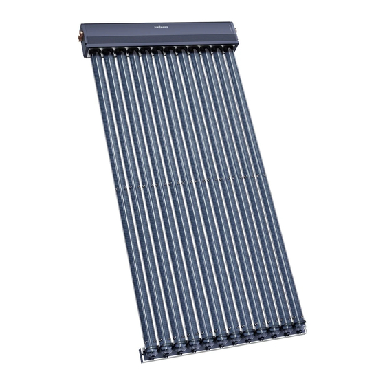
Vacuum tube collector based on the heat pipe principle
Hide thumbs
Also See for VITOSOL 200-T:
- Installation instructions manual (80 pages) ,
- Service instructions manual (24 pages) ,
- Service instructions for contractors (20 pages)

Related Manuals for Viessmann VITOSOL 200-T


Summary of Contents for Viessmann VITOSOL 200-T
- Page 1 VIESMANN Installation instructions for contractors Vitosol 200-T Type SPE Vacuum tube collector based on the heat pipe principle VITOSOL 200-T Dispose after installation. 5624 673 GB 9/2012...
- Page 2 Safety instructions Please follow these safety instructions closely to prevent accidents and mate- rial losses. Safety instructions explained ■ The Code of Practice of relevant trade associations Danger ■ All current safety regulations as This symbol warns against the defined by DIN, EN, DVGW, VDE and risk of injury.
-
Page 3: Table Of Contents
Index Installation sequence Installation on pitched roofs with roof hooks............■ Fitting roof hooks....................■ Vertical installation.................... ■ Horizontal installation..................11 Installation on pitched roofs with rafter anchors........... 16 ■ Fitting rafter anchors..................16 ■ Vertical installation.................... 18 ■ Horizontal installation..................25 Pitched roof installation with mounting brackets.......... -
Page 4: Installation On Pitched Roofs With Roof Hooks
Installation on pitched roofs with roof hooks Fitting roof hooks Roof hooks are suitable for vertical and Dimensions for horizontal and vertical horizontal collector installation. arrangement of roof hooks: ■ Vertical installation (vacuum tubes vertical, relative to the roof ridge), see pages 7 and 8. - Page 5 Installation on pitched roofs with roof hooks (cont.) Pantiled roof 30x100 38x58 Continue on page 9. Slate roof Note Fit commercially available lead flashing to protect against the ingress of mois- ture. Continue on page 9.
- Page 6 Installation on pitched roofs with roof hooks (cont.) Plain tile roof Note Trim tile; cut off approx. 30 mm with angle grinder. Continue on page 9.
-
Page 7: Vertical Installation
Installation on pitched roofs with roof hooks (cont.) Vertical installation Dimensions for vertical arrangement of roof hooks B C DE Dimension x according to the width of the tile head. A Vacuum tube G Mounting plate B Clamping bracket H Timber, 38 x 58 mm (only for pantiles) C Tube retainer K Timber, 30 x 100 mm... - Page 8 Installation on pitched roofs with roof hooks (cont.) Dimensions for horizontal arrangement of roof hooks 90° C Tube retainer E Roof hooks D Mounting rail Combination mm b mm c mm d mm e — — — — 1.63 m 1240 —...
- Page 9 Installation on pitched roofs with roof hooks (cont.) 90° 90°...
- Page 10 Installation on pitched roofs with roof hooks (cont.) 90° 90° The tube retainers must be aligned with those in the header casing; where necessary, align with a piece of string. Continue with chapter "Hydraulic con- nections" (see page 51).
-
Page 11: Horizontal Installation
Installation information Install the tube retainer offset against the header casing. This achieves a slope of the vacuum tubes towards the hori- zontal. A Header casing C Tube retainer B Mounting rails Vitosol 200-T mm b 1.63 m 3.26 m... - Page 12 Installation on pitched roofs with roof hooks (cont.) Dimensions for vertical arrangement of roof hooks A Header casing F Vacuum tube B Mounting rail G Timber, 30 x 100 mm C Tube retainer (only for pantiles) H Timber, 38 x 58 mm D Mounting bracket (only for pantiles) E Roof hooks...
- Page 13 Installation on pitched roofs with roof hooks (cont.) Dimension x according to the width of the tile head. Combination mm d mm e mm f mm g 1220 — — — 1.63 m 2390 — 1240 — — 3.26 m 1220 1220 1260...
- Page 14 Installation on pitched roofs with roof hooks (cont.) 90° 90° 90° 90° 90°...
- Page 15 Installation on pitched roofs with roof hooks (cont.) Use the centring groove on the back of the header casing as a drilling guide. Ø9 90° The tube retainers must be aligned with those in the header casing; where necessary, align with a piece of string. Continue with chapter "Hydraulic con- nections"...
-
Page 16: Installation On Pitched Roofs With Rafter Anchors
Installation on pitched roofs with rafter anchors Fitting rafter anchors Rafter anchors are suitable for vertical Rafter anchor distances and arrange- and horizontal collector installation. ment: ■ Vertical installation (vacuum tubes vertical, relative to the roof ridge), see pages 18 and 22. ■... - Page 17 Installation on pitched roofs with rafter… (cont.)
-
Page 18: Vertical Installation
Installation on pitched roofs with rafter… (cont.) Vertical installation Dimensions for horizontal arrangement of rafter anchors For each number of collectors and col- Look up the combination in the table for lector combination, a specific number of 3 collectors on page 20 (highlighted rafter anchors is allocated. - Page 19 Installation on pitched roofs with rafter… (cont.) Rafter anchor position C Tube retainer 1 collector Combination Rafter distance a Rafters used Projection b in mm in mm ≤ 600 1, 2 1 x 1.63 m ≤ 700 1, 2 ≤ 800 1, 2 ≤...
- Page 20 Installation on pitched roofs with rafter… (cont.) 3 collectors Combination Rafter distance a Rafters used Projection b in mm in mm ≤ 600 1, 2, 3, 4, 5, 6 3 x 1.63 m ≤ 700 1, 2, 3, 4, 5, 6 ≤...
- Page 21 Installation on pitched roofs with rafter… (cont.) 5 collectors Combination Rafter distance Rafters used Projection b a in mm in mm ≤ 600 1, 2, 3, 4, 5, 6, 7, 8, 9, 10 ≤ 700 — — 5 x 1.63 m ≤...
- Page 22 Installation on pitched roofs with rafter… (cont.) Dimensions for vertical arrangement of rafter anchors A Vacuum tube E Rafter anchor B Clamping bracket F Header casing C Tube retainer G Mounting plate D Mounting rail 90°...
- Page 23 Installation on pitched roofs with rafter… (cont.) 90° 90°...
- Page 24 Installation on pitched roofs with rafter… (cont.) 90° 90° The tube retainers must be aligned with those in the header casing; where necessary, align with a piece of string.
-
Page 25: Horizontal Installation
Installation information Install the tube retainer offset against the header casing. This achieves a slope of the vacuum tubes towards the hori- zontal. A Header casing C Tube retainer B Mounting rails Vitosol 200-T mm b 1.63 m 3.26 m... - Page 26 Installation on pitched roofs with rafter… (cont.) Dimensions for vertical arrangement of roof hooks A Header casing D Clamping bracket B Mounting rail E Rafter anchor C Tube retainer F Vacuum tube...
- Page 27 Installation on pitched roofs with rafter… (cont.) Dimension x according to the width of the tile head. Combination mm d mm e mm f mm g 1220 — — — 1.63 m 2390 — 1240 — — 3.26 m 1220 1220 1260 1900...
- Page 28 Installation on pitched roofs with rafter… (cont.) Dimensions for horizontal arrangement of roof hooks 90° Note Of the 3 rafters that are required for the overall width, leave the centre rafter free. B Mounting rail E Rafter anchor C Tube retainer Rafter distance k in mm Projection h in mm...
- Page 29 Installation on pitched roofs with rafter… (cont.) 90° 90° 90° 90°...
-
Page 30: Pitched Roof Installation With Mounting Brackets
Installation on pitched roofs with rafter… (cont.) Ø9 90° Pitched roof installation with mounting brackets e.g. on sheet steel roofs Vertical installation Install vacuum tubes vertically relative to the roof ridge. - Page 31 Pitched roof installation with mounting brackets (cont.) The installation may or may not be dependent on the rafter distance (differ- ent lengths of mounting rails in the instal- lation set). Dimensions for vertical arrangement of mounting brackets FG E A Vacuum tube E Mounting bracket B Clamping bracket F Header casing...
- Page 32 Pitched roof installation with mounting brackets (cont.) Dimensions for horizontal arrangement of mounting brackets For a horizontal arrangement of mount- For a horizontal arrangement of mount- ing brackets when the installation ing brackets when the installation does depends on the rafter distance, refer to not depend on the rafter distance, see the rafter distances on page 18.
- Page 33 Pitched roof installation with mounting brackets (cont.) Use on-site fixings to secure the mount- The installation is shown using box pro- ing brackets. files as an example. 90° Note Screws supplied on site. D Mounting rail H Fixing E Mounting bracket...
- Page 34 Pitched roof installation with mounting brackets (cont.) 90° 90°...
-
Page 35: Horizontal Installation
Pitched roof installation with mounting brackets (cont.) 90° 90° The tube retainers must be aligned with those in the header casing; where necessary, align with a piece of string. Continue with chapter "Hydraulic con- nections" (see page 51). Horizontal installation Install vacuum tubes parallel to the roof The installation may or may not be ridge. - Page 36 Pitched roof installation with mounting brackets (cont.) Install the tube retainer offset against the header casing. This achieves a slope of the vacuum tubes towards the hori- zontal. A Header casing C Tube retainer B Mounting rails Vitosol 200-T mm b 1.63 m 3.26 m...
- Page 37 Pitched roof installation with mounting brackets (cont.) Dimensions for vertical arrangement of mounting brackets A Header casing D Vacuum tube B Mounting rail E Mounting bracket C Tube retainer Combination mm d mm e mm f mm g 1220 — —...
- Page 38 Pitched roof installation with mounting brackets (cont.) Dimensions for horizontal arrangement of mounting brackets B Mounting rail C Tube retainer Installation independent of rafter distance Installation dependent on rafter distance...
- Page 39 Pitched roof installation with mounting brackets (cont.) Use on-site fixings to secure the mount- The installation is shown using box pro- ing brackets. files as an example. 90° Screws for mounting brackets to be supplied on site. B Mounting rail H Fixing E Mounting bracket...
- Page 40 Pitched roof installation with mounting brackets (cont.) 90° 90° 90° 90° 90° mm l Installation independent of rafter distance Installation dependent on rafter distance...
- Page 41 Pitched roof installation with mounting brackets (cont.) Ø9 90° The tube retainers must be aligned with those in the header casing; where necessary, align with a piece of string. Continue with chapter "Hydraulic con- nections" (see page 51).
-
Page 42: Elevated Installation
Elevated installation If several collectors are installed 2. To calculate dimension z: behind each other, maintain distance h = 2260 mm z to prevent shading. α = 45° β = 16.5° 1. Determine the angle β of the sun on 21 December (the shortest day of the year) at midday. - Page 43 ■ Calculation of ballast and max. load on the substructure according to DIN 1055-4: 2005-03 and DIN 1055-5: 2005-07. Two support slabs each A and B are required respectively for each collec- tor. For the calculation, the Viessmann "SOLSTAT" calculation program is available at www.viessmann.com.
- Page 44 Elevated installation (cont.) A Support slab A C Collector support B Support slab B Combination mm b 600/600 1.63 m /1.63 m 600/1200 1.63 m /3.26 m 1200/1200 1235 3.26 m /3.26 m...
- Page 45 Elevated installation (cont.) Ø8.5...
-
Page 46: Horizontal Installation
Elevated installation (cont.) The tube retainers must be in line with those in the header casing; where necessary, align with a piece of string. Continue with chapter "Hydraulic con- nections" (see page 51). Horizontal installation e.g. on flat roofs... - Page 47 ■ Calculation of ballast and max. load on the substructure according to DIN 1055-4: 2005-03 and DIN 1055-5: 2005-07. Two support slabs each A and B are required respectively for each collec- tor. For the calculation, the Viessmann "SOLSTAT" calculation program is available at www.viessmann.com.
- Page 48 Horizontal installation (cont.) 90° 90° Note Screws supplied on site. A Support slab A B Support slab B...
- Page 49 Horizontal installation (cont.) Combination mm b mm c — — 1.63 m 1240 — — 3.26 m 1260 1920 1.63 m /1.63 m 1550 2790 1.63 m /3.26 m 1240 2150 2790 3.26 m /1.63 m 1240 2430 3670 3.26 m /3.26 m 90°...
- Page 50 Horizontal installation (cont.) 90° The tube retainers must be aligned with those in the header casing; where necessary, align with a piece of string. Continue with chapter "Hydraulic con- nections" (see page 51).
-
Page 51: Hydraulic Connections
Hydraulic connections Connecting the header casing Components Please note Connection pipes should not show any signs of damage. Lubricate all O-ring seals on the collectors only with the special grease provided. Hook collector fastening A into the holes in the header casing. -
Page 52: Fitting The Connection Set
Hydraulic connections (cont.) Fitting the connection set Components Installation information ■ Initially turn the union nut by hand, ■ All pipes must be cut at a right angle then tighten with an open ended span- and deburred. ner by a further ¾ turn. ■... - Page 53 Hydraulic connections (cont.) After joining the collector array to the "Vitosol-T" service instructions. pipework of the solar circuit, fill the sys- tem, check the system pressure and test for tightness.
-
Page 54: Fitting The Vacuum Tubes
Fitting the vacuum tubes Danger The vacuum tubes can break if max. 45° insufficient care is taken. This can result in injuries. The con- denser becomes very hot under insolation. Wear gloves and safety gog- gles. Please note Installation information The tube holder bracket can ■... -
Page 55: Fitting The Collector Temperature Sensor
Fitting the vacuum tubes (cont.) +45° 0° -45° 0° -45° Fitting the collector temperature sensor Installation information Please note ■ Fit the sensor near the hydraulic con- Route the sensor lead so that it nection. does not come into contact with the hot tubes. - Page 56 Fitting the collector temperature sensor (cont.) 3 Nm...
- Page 57 Fitting the collector temperature sensor (cont.) Please note The collectors may be damaged if the solar thermal system is not filled with heat transfer medium immediately after installation. Therefore, protect the collectors against insolation by covering them up.
-
Page 58: Installation
"Vitosol" there. Metal seal connections, locking service instructions. ring fittings or Viessmann plug-in con- nections with double O-rings are the ■ When operating without a Solar-Divi- most suitable. con, only use safety valves designed If other seals such as flat gaskets are for 120°C, a maximum pressure of 6... - Page 59 Installation (cont.) A Collector H Manual solar fill pump B Solar-Divicon K Fill valve (F, G, L) C Drip container L Drain D Expansion vessel M Air separator E Stagnation heat sink N DHW cylinder F Shut-off valve O Solar control unit G Filling P Air vent valve...
-
Page 60: Commissioning
Commissioning For commissioning the solar ther- mal system, see the "Vitosol" service instructions. Viessmann Werke GmbH&Co KG Viessmann Limited D-35107 Allendorf Hortonwood 30, Telford Telephone: +49 6452 70-0 Shropshire, TF1 7YP, GB Fax: +49 6452 70-2780 Telephone: +44 1952 675000 www.viessmann.com...
Need help?
Do you have a question about the VITOSOL 200-T and is the answer not in the manual?
Questions and answers