Table of Contents
Advertisement
VIESMANN
Technical guide
VITOSOL 100-FM/-F
Flat-plate collector, type SV and SH
For installation on flat and pitched roofs and for freestanding
installation
Type SH also for installation on walls
VITOSOL 200-FM/-F
Flat-plate collector, type SV2F/SH2F, SV2D
For installation on flat and pitched roofs and for freestanding
installation
Type SH also for installation on walls
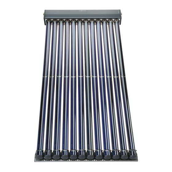
VITOSOL 300-TM
Type SP3C
For installation on flat or pitched roofs, on walls and for free-
standing installation
5822 440 GB
8/2017
Flat-plate collectors and vacuum tube collectors
Flat and pitched roof installation, and wall mounting
VITOSOL 200-TM
Type SPEA
For installation on flat and pitched roofs and for freestanding
installation
VITOSOL
Advertisement
Table of Contents


Need help?
Do you have a question about the Vitosol 100-FM and is the answer not in the manual?
Questions and answers