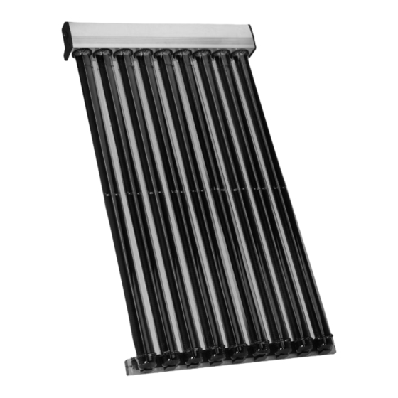
Viessmann VITOSOL 200-T Installation Instructions Manual
Vacuum tube collector based on the heat pipe principle
Hide thumbs
Also See for VITOSOL 200-T:
- Installation instructions manual (80 pages) ,
- Service instructions manual (24 pages) ,
- Service instructions for contractors (20 pages)

Related Manuals for Viessmann VITOSOL 200-T


Summary of Contents for Viessmann VITOSOL 200-T
- Page 1 VIESMANN Installation instructions for contractors Vitosol 200-T Type SPE Vacuum tube collector based on the heat pipe principle VITOSOL 200-T Dispose after installation. 5773 817 GB 6/2013...
- Page 2 Safety instructions Please follow these safety instructions closely to prevent accidents and mate- rial losses. Safety instructions explained ■ The Code of Practice of relevant trade associations Danger ■ All current safety regulations as This symbol warns against the defined by DIN, EN, DVGW, VDE and risk of injury.
-
Page 3: Table Of Contents
Index Intended use....................... Installation sequence Installation on pitched roofs with roof hooks............■ Fitting roof hooks....................■ Vertical installation.................... ■ Horizontal installation..................12 Installation on pitched roofs with rafter hooks............16 ■ Fitting rafter hooks.................... 16 ■ Vertical installation.................... 18 ■... -
Page 4: Intended Use
Intended use The appliance is only intended to be installed and operated in sealed unven- ted systems that comply with EN 12828 / DIN 1988, or solar thermal systems that comply with EN 12977, with due atten- tion paid to the associated installation, service and operating instructions. -
Page 5: Installation On Pitched Roofs With Roof Hooks
Installation on pitched roofs with roof hooks Fitting roof hooks Roof hooks are suitable for vertical and ■ Vertical installation (vacuum tubes horizontal collector installation. vertical, relative to the roof ridge), see from page 8 ■ Horizontal installation (vacuum tubes parallel, relative to the roof ridge), see from page 12 1 Timber... - Page 6 Installation on pitched roofs with roof hooks (cont.) Pantiled roof 30x100 38x58 Slate roof Note Fit commercially available lead flashing to protect against the ingress of mois- ture.
- Page 7 Installation on pitched roofs with roof hooks (cont.) Plain tile roof Note Trim tile; cut off approx. 30 mm with an angle grinder. Corrugated sheet roof Ø8 A Sealing washer (on site) B Existing roof batten...
-
Page 8: Vertical Installation
Installation on pitched roofs with roof hooks (cont.) Vertical installation Dimensions for vertical arrangement of roof hooks B C DE Dimension x according to the width of the tile head. A Vacuum tubes G Retaining bracket B Clamping bracket H Timber, 38 x 58 mm C Tube retainer (only for pantiles) K Timber, 30 x 100 mm... - Page 9 Installation on pitched roofs with roof hooks (cont.) 90° C Tube retainer E Roof hook D Mounting rail Combination mm b mm c mm d mm e — — — — 1.63 m 1240 — — — — 3.26 m 1265 1875 1.63 m...
- Page 10 Installation on pitched roofs with roof hooks (cont.) 90° 90°...
- Page 11 Installation on pitched roofs with roof hooks (cont.) 90° 90° y = 275 mm Information on step 6: Continue with chapter "Hydraulic con- The tube retainers must be aligned with nections" (see page 61). those in the header casing; where nec- essary, align with a piece of string.
-
Page 12: Horizontal Installation
Installation on pitched roofs with roof hooks (cont.) Horizontal installation Dimensions for vertical arrangement of roof hooks Dimension x according to the width of the tile head. A Header casing E Roof hook B Mounting rail F Vacuum tubes C Tube retainer G Timber, 30 x 100 mm D Mounting bracket (only for pantiles) - Page 13 Installation on pitched roofs with roof hooks (cont.) H Timber, 38 x 58 mm (only for pantiles) Combination mm d mm e mm f mm g 1220 — — — 1.63 m 2390 — 1240 — — 3.26 m 1220 1220 1260 1900...
- Page 14 Installation on pitched roofs with roof hooks (cont.) 90° 90° 90° 90° 90° 90° Note dimension b in the following table.
- Page 15 This inclines the vac- uum tubes towards the horizontal. Ø9 90° Information on step 9: Vitosol 200-T mm b Use the centring groove on the back of 1.63 m the header casing as a drilling guide. 3.26 m...
-
Page 16: Installation On Pitched Roofs With Rafter Hooks
Installation on pitched roofs with roof hooks (cont.) Continue with chapter "Hydraulic con- nections" (see page 61). Installation on pitched roofs with rafter hooks Fitting rafter hooks Rafter hooks are suitable for vertical ■ Vertical installation (vacuum tubes and horizontal collector installation. vertical, relative to the roof ridge), see from page 18 ■... - Page 17 Installation on pitched roofs with rafter hooks (cont.)
-
Page 18: Vertical Installation
Installation on pitched roofs with rafter hooks (cont.) Vertical installation Dimensions for horizontal arrangement of rafter hooks For each number of collectors and col- Example: lector combination, a specific number of ■ 3 collectors rafter hooks is allocated. ■ Combination comprising 1 x 1.63 m Subject to the distance between rafters, and 2 x 3.26 m use a specific number of rafters on which... - Page 19 Installation on pitched roofs with rafter hooks (cont.) Look up the combination in the table for 3 collectors on page 20 (highlighted grey): Of the 10 rafters, the following are used: Rafters 1, 2, 3, 6, 7, 10 Rafter hook position A Tube retainer 1 collector Combination...
- Page 20 Installation on pitched roofs with rafter hooks (cont.) 3 collectors Combination Rafter spacing a in mm Rafters used ≤ 600 1, 2, 3, 4, 5, 6 ≤ 700 1, 2, 3, 4, 5, 6 3 x 1.63 m ≤ 800 —...
- Page 21 Installation on pitched roofs with rafter hooks (cont.) 5 collectors Combination Rafter spacing a in mm Rafters used ≤ 600 1, 2, 3, 4, 5, 6, 7, 8, 9, 10 5 x 1.63 m ≤ 700 — ≤ 800 — ≤...
- Page 22 Installation on pitched roofs with rafter hooks (cont.) Dimensions for vertical arrangement of rafter hooks 90°...
- Page 23 Installation on pitched roofs with rafter hooks (cont.) 90° 90° x = 42 mm...
- Page 24 Installation on pitched roofs with rafter hooks (cont.) 90° 90° y = 296 mm Information on step 6: Continue with chapter "Hydraulic con- The tube retainers must be aligned with nections" (see page 61). those in the header casing; where nec- essary, align with a piece of string.
-
Page 25: Horizontal Installation
Installation on pitched roofs with rafter hooks (cont.) Horizontal installation Dimensions for vertical arrangement of rafter hooks Combination mm d mm e mm f mm g 1220 — — — 1.63 m 2390 — 1240 — — 3.26 m 1220 1220 1260 1900... - Page 26 Installation on pitched roofs with rafter hooks (cont.) 3 rafters are required for the overall width. Leave the centre rafter free. 90° A Rafter hook C Tube retainer B Mounting rail Rafter spacing k in mm Projection h in mm...
- Page 27 Installation on pitched roofs with rafter hooks (cont.) 90° 90° 90° 90° 90° 90° 90° Note dimension b in the following table. Install the header casing offset against the tube retainer. This inclines the vac- uum tubes towards the horizontal.
- Page 28 Installation on pitched roofs with rafter hooks (cont.) Ø9 90° Continue with chapter "Hydraulic con- Vitosol 200-T mm b nections" (see page 61). 1.63 m 3.26 m Information on step 9: Use the centring groove on the back of the header casing as a drilling guide.
-
Page 29: Installation On Pitched Roofs With Rafter Anchors
Installation on pitched roofs with rafter anchors Fitting rafter anchors Rafter anchors are suitable for vertical ■ Vertical installation (vacuum tubes and horizontal collector installation. vertical, relative to the roof ridge), see from page 33 ■ Horizontal installation (vacuum tubes parallel, relative to the roof ridge), see from page 37... - Page 30 Installation on pitched roofs with rafter… (cont.) 5 Seal Vertical installation 1 Rafter anchor 6 Plastic replacement tile, if the exist- 2 Mounting rail ing tile is not to be cut 5 Seal Use only on roofs with a slope of at 6 Plastic replacement tile, if the exist- least 12°.
- Page 31 Installation on pitched roofs with rafter… (cont.) Installation involving trimming tiles...
- Page 32 Installation on pitched roofs with rafter… (cont.) Installation involving plastic replacement tiles...
-
Page 33: Vertical Installation
Installation on pitched roofs with rafter… (cont.) Vertical installation Dimensions for horizontal arrangement of rafter anchors See from page 18. - Page 34 Installation on pitched roofs with rafter… (cont.) Dimensions for vertical arrangement of rafter anchors A Vacuum tubes E Rafter anchor B Clamping bracket F Header casing C Tube retainer G Retaining bracket D Mounting rail 90°...
- Page 35 Installation on pitched roofs with rafter… (cont.) 90° 90°...
- Page 36 Installation on pitched roofs with rafter… (cont.) 90° 90° Information on step 6: Continue with chapter "Hydraulic con- The tube retainers must be aligned with nections" (see page 61). those in the header casing; where nec- essary, align with a piece of string.
-
Page 37: Horizontal Installation
Installation on pitched roofs with rafter… (cont.) Horizontal installation Dimensions for vertical arrangement of rafter anchors A Header casing D Clamping bracket B Mounting rail E Rafter anchor C Tube retainer F Vacuum tubes... - Page 38 Installation on pitched roofs with rafter… (cont.) Combination mm d mm e mm f mm g 1220 — — — 1.63 m 2390 — 1240 — — 3.26 m 1220 1220 1260 1900 1.63 m /1.63 m 1220 2390 1550 2786 1.63 m /3.26 m...
- Page 39 Installation on pitched roofs with rafter… (cont.) 3 rafters are required for the overall width. Leave the centre rafter free. 90° B Mounting rail E Rafter anchor C Tube retainer Rafter spacing k in mm Projection h in mm...
- Page 40 Installation on pitched roofs with rafter… (cont.) 90° 90° 90° 90° 90° 90° 90° Note dimension b in the following table. Install the header casing offset against the tube retainer. This inclines the vac- uum tubes towards the horizontal.
- Page 41 Installation on pitched roofs with rafter… (cont.) Ø9 90° Vitosol 200-T mm b Continue with chapter "Hydraulic con- nections" (see page 61). 1.63 m 3.26 m Information on step 10: Use the centring groove on the back of the header casing as a drilling guide.
-
Page 42: Pitched Roof Installation With Mounting Bracket
Pitched roof installation with mounting bracket For example on sheet steel roofs Vertical installation Vacuum tubes vertical, relative to the roof ridge Dimensions for vertical arrangement of mounting brackets FG E A Vacuum tubes E Mounting bracket B Clamping bracket F Header casing C Tube retainer G Retaining bracket... - Page 43 Pitched roof installation with mounting bracket (cont.) Dimensions for horizontal arrangement of mounting brackets Horizontal arrangement of mounting Horizontal arrangement of mounting brackets when the installation depends brackets when the installation does not on the rafter spacing, is subject to the depend on rafter spacing, see the fol- rafter spacing (see from page 18).
- Page 44 Pitched roof installation with mounting bracket (cont.) Use on-site fixings to secure mounting The installation is shown using box pro- brackets. files as an example. 90° D Mounting rail H Fixings and screws to be provided E Mounting bracket on site...
- Page 45 Pitched roof installation with mounting bracket (cont.) 90° 90°...
-
Page 46: Horizontal Installation
Pitched roof installation with mounting bracket (cont.) 90° 90° Information on step 8: Continue with chapter "Hydraulic con- The tube retainers must be aligned with nections" (see page 61). those in the header casing; where nec- essary, align with a piece of string. Horizontal installation Vacuum tubes parallel, relative to the roof ridge... - Page 47 Pitched roof installation with mounting bracket (cont.) Dimensions for vertical arrangement of mounting brackets A Header casing D Vacuum tubes B Mounting rail E Mounting bracket C Tube retainer Combination mm d mm e mm f mm g 1220 — —...
- Page 48 Pitched roof installation with mounting bracket (cont.) Dimensions for horizontal arrangement of mounting brackets 3 rafter hooks are required for the whole width when installing them on rafters. Leave the centre rafter free. B Mounting rail C Tube retainer...
- Page 49 Pitched roof installation with mounting bracket (cont.) Use on-site fixings to secure mounting The installation is shown using box pro- brackets. files as an example. 90° B Mounting rail H Fixings and screws to be provided E Mounting bracket on site...
- Page 50 Pitched roof installation with mounting bracket (cont.) 90° 90° 90° 90° 90° 90° 90° Note dimension b in the following table. Install the header casing offset against the tube retainer. This inclines the vac- uum tubes towards the horizontal.
- Page 51 Pitched roof installation with mounting bracket (cont.) Ø9 90° Vitosol 200-T mm b Information on step 11: Use the centring groove on the back of 1.63 m the header casing as a drilling guide. 3.26 m...
-
Page 52: Elevated Installation
Pitched roof installation with mounting bracket (cont.) Continue with chapter "Hydraulic con- nections" (see page 61). Elevated installation If several collectors are installed 2. To calculate dimension z: behind each other, prevent shading. h = 2260 mm Maintain clearance z between the α... - Page 53 ■ Observe the maximum load and dis- support slabs B are required. tance from the edge of the roof for the The Viessmann "SOLSTAT" calcula- on-site substructure to DIN 1055. tion program is available at ■ Remove any gravel or similar from the www.viessmann.com to assist with...
- Page 54 Elevated installation (cont.) 8. 1. Use the mounting feet as a drilling template. A Support slab A C Collector support B Support slab B Collector area Installation angle 30° 2413 1.63 m 45° 2200 1200 3.26 m 60° 1838 Combination 1.63 m /1.63 m 1.63 m...
- Page 55 Elevated installation (cont.) Ø8.5...
-
Page 56: Horizontal Installation
Elevated installation (cont.) Information on step 6: Continue with chapter "Hydraulic con- The tube retainers must be in line with nections" (see page 61). those in the header casing; where nec- essary, align with a piece of string. Horizontal installation For example on flat roofs Installation information ■... - Page 57 Per collector, 2 support slabs A and 2 array due south. support slabs B are required. ■ Calculation of ballast and max. load on The Viessmann "SOLSTAT" calcula- the substructure according to DIN tion program is available at 1055-4: 2005-03 and DIN 1055-5: www.viessmann.com to assist with...
- Page 58 Horizontal installation (cont.) 90° 90° Screws to be supplied on site A Support slab A B Support slab B...
- Page 59 Horizontal installation (cont.) Combination mm b mm c — — 1.63 m 1240 — — 3.26 m 1260 1920 1.63 m /1.63 m 1550 2790 1.63 m /3.26 m 1240 2150 2790 3.26 m /1.63 m 1240 2430 3670 3.26 m /3.26 m 90°...
- Page 60 Horizontal installation (cont.) 90° Information on step 8: Continue with chapter "Hydraulic con- The tube retainers must be aligned with nections" (see page 61). those in the header casing; where nec- essary, align with a piece of string.
-
Page 61: Hydraulic Connections
Hydraulic connections Connecting the header casing Components Please note Connection pipes should not show any signs of damage. Lubricate all O-ring seals on the collectors only with the special grease provided. Information on step 4: Hook collector fastening A through the holes in the header casing. -
Page 62: Fitting The Connection Set
Hydraulic connections (cont.) Fitting the connection set Components Installation information ■ Initially turn the union nut by hand, ■ All pipes must be cut at a right angle then tighten with an open ended span- and deburred. ner by a further ¾ turn. ■... - Page 63 Hydraulic connections (cont.) After joining the collector array to the "Vitosol-T" service instructions pipework of the solar circuit, fill the sys- tem, check the system pressure and test for tightness.
-
Page 64: Fitting Vacuum Tubes
Fitting vacuum tubes Danger For roofs deviating from due south, The vacuum tubes can break if adjust the angle of inclination of the insufficient care is taken, which absorber (see scale in illustration on could lead to injuries. The con- page 65). -
Page 65: Fitting The Collector Temperature Sensor
Fitting vacuum tubes (cont.) +45° 0° -45° 0° -45° Fitting the collector temperature sensor Installation information Please note ■ Fit the sensor near the hydraulic con- Route the sensor lead so that it nection. does not come into contact with the hot tubes. - Page 66 Fitting the collector temperature sensor (cont.) 3 Nm...
- Page 67 Fitting the collector temperature sensor (cont.) Please note The collectors may be damaged if the solar thermal system is not filled with heat transfer medium immediately after installation. Therefore, protect the collectors against insolation by covering them up.
-
Page 68: Installation
120 °C, with a maximum pressure occur there. Metal seal connections, of 6 bar which carry the "S" (Solar) locking ring fittings or Viessmann plug- designation. in connections with double O-rings are the most suitable. - Page 69 Installation (cont.) A Solar-Divicon K Fill valve B Shut-off valves L Stagnation heat sink C Non-return valves M Expansion vessel D Solar circuit pump N Drip pan E Air separator O Collector F Shut-off valve (adjusting screw P Solar control unit above flow indicator H) R DHW cylinder G Drain valve...
-
Page 70: Commissioning
Commissioning "Vitosol" service instructions... - Page 72 Viessmann Werke GmbH&Co KG Viessmann Limited D-35107 Allendorf Hortonwood 30, Telford Telephone: +49 6452 70-0 Shropshire, TF1 7YP, GB Fax: +49 6452 70-2780 Telephone: +44 1952 675000 www.viessmann.com Fax: +44 1952 675040 E-mail: info-uk@viessmann.com...
Need help?
Do you have a question about the VITOSOL 200-T and is the answer not in the manual?
Questions and answers