Viessmann VITOSOL 200-T Installation Instructions Manual
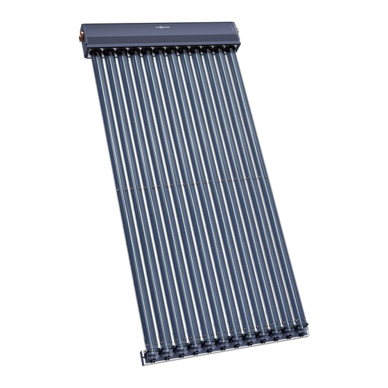
Vacuum tube collector based on the heat pipe principle. type sp2
Hide thumbs
Also See for VITOSOL 200-T:
- Installation instructions manual (80 pages) ,
- Service instructions manual (24 pages) ,
- Service instructions for contractors (20 pages)

Related Manuals for Viessmann VITOSOL 200-T


Summary of Contents for Viessmann VITOSOL 200-T
- Page 1 VIESMANN Installation instructions for contractors Vitosol 200-T Type SP2 Vacuum tube collector based on the heat pipe principle VITOSOL 200-T Dispose after installation. 5727 196 GB 6/2010...
- Page 2 Safety instructions Please follow these safety instructions closely to prevent accidents and mate- rial losses. Safety instructions explained ■ All current safety regulations as defined by DIN, EN, DVGW, VDE and Danger all locally applicable standards. This symbol warns against the a ÖNORM, EN and ÖVE risk of injury.
-
Page 3: Table Of Contents
Index Installation sequence Horizontal above roof installation................. ■ Installation with rafter anchors................■ Installation with mounting brackets..............13 ■ Installing the header casing................16 Vertical above roof installation................17 ■ Observe prior to installation................17 ■ Installation with rafter anchors................20 ■... -
Page 4: Horizontal Above Roof Installation
Horizontal above roof installation Installation with rafter anchors Components M8x25 Ø8.4 / 2 1... - Page 5 Horizontal above roof installation (cont.) Overview Combination mm b mm c mm d mm e 1439 — — — 2148 — 1260 — — 1439 1439 1520 2370 /2 m 1439 2148 1670 2930 /3 m 2148 1439 1260 2080 2930 /2 m 2148...
- Page 6 Horizontal above roof installation (cont.) Installation...
- Page 7 Horizontal above roof installation (cont.) For the distance between the rafter anchors, see page 5. Installation of the rafter anchors: Of the 3 rafters that are required for the overall width, leave the centre rafter A free.
- Page 8 Horizontal above roof installation (cont.)
- Page 9 Horizontal above roof installation (cont.)
- Page 10 Horizontal above roof installation (cont.) 90° 90° Rafter distance d in mm Projection e in mm...
- Page 11 Information regarding fitting the rail Fit the mounting rails with tube holders offset against each other. This achieves a slope of the vacuum tubes towards the horizontal. A Header casing B Mounting rails with tube holders Vitosol 200-T mm b mm c...
- Page 12 Horizontal above roof installation (cont.) 90° 90° 90° 90°...
-
Page 13: Installation With Mounting Brackets
Horizontal above roof installation (cont.) 90° 90° Continue with chapter "Making the hydraulic connections". Installation with mounting brackets For example, installation on sheet steel roofs. - Page 14 Horizontal above roof installation (cont.) Components M8x25 Ø8.4 / 2 1 Overview...
- Page 15 Horizontal above roof installation (cont.) Combination mm b mm c mm d mm e 1439 — — — 2148 — 1260 — — 1439 1439 1520 2370 /2 m 1439 2148 1670 2930 /3 m 2148 1439 1260 2080 2930 /2 m 2148 2148...
-
Page 16: Installing The Header Casing
Horizontal above roof installation (cont.) Installing the header casing Use the centring groove on the back of the header casing as a drilling guide. Ø9 90°... -
Page 17: Vertical Above Roof Installation
Vertical above roof installation Observe prior to installation For each number of collectors and col- Example: lector combination, a specific number of ■ Number of collectors 3 rafter anchors or mounting brackets (in ■ Combination comprising 1 x 2 m connection with sheet steel roofs) is allo- 2 x 3 m cated. - Page 18 Vertical above roof installation (cont.) Always maintain the following dimen- sions: ■ Dimension b, projection of the mount- ing rails with tube holders, see the fol- lowing tables ■ Dimension c = 81 mm 1 collector Combination Rafter distance a Rafters used b in mm in mm...
- Page 19 Vertical above roof installation (cont.) 3 collectors Combination Rafter distance a Rafters used b in mm in mm ≤ 600 1, 2, 3, 5, 6, 8 2 x 2 m ≤ 700 1, 2, 3, 4, 5, 7 1 x 3 m ≤...
-
Page 20: Installation With Rafter Anchors
Vertical above roof installation (cont.) Installation with rafter anchors Components / 2 1 / 2 1 Ø8,4 M8x25... - Page 21 Vertical above roof installation (cont.) Overview 1360...
- Page 22 Vertical above roof installation (cont.) Installation Dimension a = 1650 mm...
- Page 23 Vertical above roof installation (cont.)
- Page 24 Vertical above roof installation (cont.)
- Page 25 Vertical above roof installation (cont.)
- Page 26 Vertical above roof installation (cont.) 90° 90° Dimension c = 81 mm...
-
Page 27: Installation With Mounting Brackets
Vertical above roof installation (cont.) Note Tube holders on opposite rails must be aligned. 90° Continue with chapter "Making the hydraulic connections". Installation with mounting brackets For example, installation on sheet steel roofs. - Page 28 Vertical above roof installation (cont.) Components Ø8,4 M8x25 / 2 1 / 2 1 Overview 1360...
- Page 29 Vertical above roof installation (cont.) Installation Use on-site fixing elements A to The installation of the mounting bracket secure the brackets. is shown using box profiles as an exam- ple. 90° Continue with step 20 on page 26.
-
Page 30: Installing The Header Casing
Vertical above roof installation (cont.) Installing the header casing 90° 90° Making the hydraulic connections Connecting the header casing Components Please note Installation information Connection pipes should not ■ Click retaining clips into the groove in show any signs of damage. the connection pipes through the holes Lubricate all O-ring seals on the in the collector connectors. -
Page 31: Fitting The Connection Set
Making the hydraulic connections (cont.) Fitting the connection set Components... - Page 32 Making the hydraulic connections (cont.) Installation information ■ Initially turn the union nut by hand, ■ All pipes must be cut at a right angle then tighten with an open ended span- and deburred. ner by a further ¾ turn. ■...
-
Page 33: Fitting The Vacuum Tubes
Making the hydraulic connections (cont.) ■ Use the U-pipe with air vent valve "Vitosol-T" service instruc- only for horizontal collector installa- tions. tions. ■ Click retaining clips into the groove through the holes in the collector con- nectors. ■ After joining the collector array to the pipework of the solar circuit, fill the system, check the system pressure and test for leaks. - Page 34 Making the hydraulic connections (cont.)
-
Page 35: Fitting The Collector Temperature Sensor
Fitting the collector temperature sensor Installation information Please note ■ The first and last tubes of a collector Route the sensor lead so that it must be secured to the twin-pipe heat does not come into contact with exchanger with a clip. the hot tubes. -
Page 36: Installation
"Vitosol" there. Metal seal connections, locking service instructions. ring fittings or Viessmann plug-in con- nections with double O-rings are the ■ When operating without a Solar-Divi- most suitable. con, only use safety valves designed If other seals such as flat gaskets are for 120°C, a maximum pressure of 6... -
Page 37: Commissioning And Adjustment
Installation (cont.) A Collector H Manual solar fill pump B Solar-Divicon K Fill valve (F, G, L) C Drip container L Drain D Expansion vessel M Air separator E Stagnation heat sink N DHW cylinder F Shut-off valve O Solar control unit G Filling P Air vent valve Commissioning and adjustment... - Page 40 Viessmann Werke GmbH&Co KG Viessmann Limited D-35107 Allendorf Hortonwood 30, Telford Telephone: +49 6452 70-0 Shropshire, TF1 7YP, GB Fax: +49 6452 70-2780 Telephone: +44 1952 675000 www.viessmann.com Fax: +44 1952 675040 E-mail: info-uk@viessmann.com...
Need help?
Do you have a question about the VITOSOL 200-T and is the answer not in the manual?
Questions and answers