Viessmann Vitosol 200-T Installation Instructions Manual
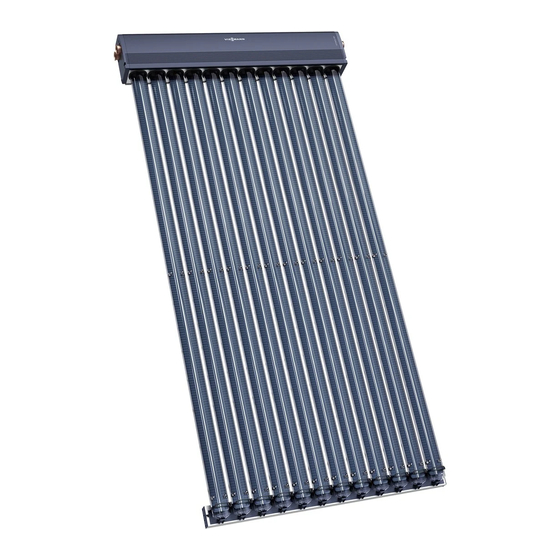
Vacuum tube collector based on the heat pipe principle type sp2
Hide thumbs
Also See for Vitosol 200-T:
- Installation instructions manual (80 pages) ,
- Service instructions manual (24 pages) ,
- Service instructions for contractors (20 pages)

Subscribe to Our Youtube Channel
Related Manuals for Viessmann Vitosol 200-T


Summary of Contents for Viessmann Vitosol 200-T
-
Page 1: Installation Instructions
VIESMANN Installation instructions for contractors Vitosol 200-T Type SP2 Vacuum tube collector based on the heat pipe principle VITOSOL 200-T Dispose after installation. 5458 006 GB 6/2010... -
Page 2: Safety Instructions
Safety instructions Please follow these safety instructions closely to prevent accidents and mate- rial losses. Safety instructions explained ■ All current safety regulations as defined by DIN, EN, DVGW, VDE and Danger all locally applicable standards. This symbol warns against the a ÖNORM, EN and ÖVE risk of injury. -
Page 3: Table Of Contents
Index Installation sequence Horizontal above roof installation................. ■ Installation with roof hooks................■ Installation with mounting brackets..............13 Vertical above roof installation................17 ■ Installation with roof hooks................17 ■ Installation with mounting brackets..............24 Installation on supports..................28 ■ Components...................... 28 ■... -
Page 4: Horizontal Above Roof Installation
Horizontal above roof installation Installation with roof hooks Components / 2 1 Pantiled roof Plain tiles 1 Timber 9 Roof hook 4 Zinc-plated countersunk chipboard ■ 38 x 58 x 2430 mm ■ 30 x 100 x 2430 mm screw (Spax-s) 5 x 80 mm 2 Roof hook 3 Zinc-plated countersunk chipboard For all types of roofing... - Page 5 Horizontal above roof installation (cont.) Dimensions overview Dimension x according to the width of the tile head. For dimensions a to e, see the following table. A Spacer F Timber, 38 x 100 mm B Header casing (only for pantiles) C Mounting bracket G Timber, 30 x 58 mm (only for pantiles)
- Page 6 Horizontal above roof installation (cont.) Combination mm b mm c mm d mm e 1439 — — — 2149 — 1260 — — 1439 1439 1520 2370 /2 m 1439 2148 1670 2930 /3 m 2148 1439 1260 2080 2930 /2 m 2148 2148...
- Page 7 Horizontal above roof installation (cont.) 30 x 100 38 x 58 Continue with chapter "Fitting mounting rails". Slate roof Observe dimensions in chapter "Dimen- Note sions overview". Fit commercially available lead flashing to protect against the ingress of mois- ture. Continue with chapter "Fitting mounting rails".
- Page 8 Horizontal above roof installation (cont.) Corrugated sheet roof Observe dimensions in chapter "Dimen- Continue with chapter "Fitting mounting sions overview". rails". Ø8 A Sealing washer (on site) B Existing roof batten Plain tiles Observe dimensions in chapter "Dimen- sions overview".
- Page 9 This achieves a slope of the vacuum tubes towards the horizontal. Trim tile with angle grinder; cut off approx. 30 mm. A Header casing B Mounting rail with tube holders Vitosol 200-T mm b mm c...
- Page 10 Horizontal above roof installation (cont.) 90° A Roof hook...
- Page 11 Horizontal above roof installation (cont.) 90° 90° 90°...
- Page 12 Horizontal above roof installation (cont.) If several collectors are fitted above each other 90° qW qEqRqO Installing the header casing Use the centring nut on the back of the header casing as a drilling guide.
-
Page 13: Installation With Mounting Brackets
Horizontal above roof installation (cont.) Continue with chapter "Making the hydraulic connections". Ø9 90° Installation with mounting brackets Components For example, installation on sheet steel Use on-site fixings to secure the brack- roofs. ets (e.g. for box profiles). - Page 14 Horizontal above roof installation (cont.) / 2 1 qP Mounting bracket qZ Mounting rail with tube holders qQ Clamping bracket qU Mounting plate qW T-slot bolt qI Locking bracket qE Washer qO Spacer qR Hexagon nut wP Retaining rubber qT Mounting rail...
- Page 15 Horizontal above roof installation (cont.) Dimensions overview A Spacer D Mounting rail with tube holders B Header casing H Mounting rail C Mounting bracket Combination mm b mm c mm d mm e 1439 — — — 2148 — 1260 —...
- Page 16 Horizontal above roof installation (cont.) Installation Fit mounting rails offset against each other (see page 9). 90° 90° Screws for mounting brackets to be supplied on site. Proceed as follows: ■ See chapter "Fitting mounting rails". ■ See chapter "Making the hydraulic connections".
-
Page 17: Vertical Above Roof Installation
Vertical above roof installation Installation with roof hooks Components / 2 1 Pantiled roof Plain tiles 1 Timber 9 Roof hook ■ 38 x 58 x 2430 mm 4 Zinc-plated countersunk chipboard ■ 30 x 100 x 2430 mm screw (Spax-s) 5 x 80 mm 2 Roof hook 3 Zinc-plated countersunk chipboard For all types of roofing... - Page 18 Vertical above roof installation (cont.) Dimensions overview AB C D E F G B C H K B Dimension x according to the width of the tile head. A Vacuum tube G Timber, 30 x 100 mm (only for pantiles) B Clamping bracket H Mounting plate C Mounting rail with tube holders...
- Page 19 Vertical above roof installation (cont.) Note For installations without roof hooks, mounting brackets are used in place of roof hooks. Combination mm b mm c mm d mm e — — — — 1260 — — — — 1520 2370 /2 m 1875 1260...
- Page 20 Vertical above roof installation (cont.) 30 x 100 38 x 58 Continue with chapter "Fitting mounting rails". Slate roof Observe dimensions in chapter "Dimen- Note sions overview". Fit commercially available lead flashing to protect against the ingress of mois- ture. Continue with chapter "Fitting mounting rails".
- Page 21 Vertical above roof installation (cont.) Corrugated sheet roof Observe dimensions in chapter "Dimen- Continue with chapter "Fitting mounting sions overview". rails". Ø8 A Sealing washer (on site) B Existing roof batten Plain tiles Observe dimensions in chapter "Dimen- sions overview".
- Page 22 Vertical above roof installation (cont.) 90° Trim tile with angle grinder; cut off approx. 30 mm. Fitting mounting rails 90° A Roof hook...
- Page 23 Vertical above roof installation (cont.) 90° Note f = 81 mm Tube holders on opposite rails must be aligned.
-
Page 24: Installation With Mounting Brackets
Vertical above roof installation (cont.) Installing the header casing 90° Note Continue with chapter "Making the The tube holders on the mounting rails hydraulic connections". must be aligned with those in the header casing; where necessary, align with a piece of string. Installation with mounting brackets Components For example, installation on sheet steel... - Page 25 Vertical above roof installation (cont.) / 2 1 qP Mounting bracket qZ Mounting rail with tube holders qQ Clamping bracket qU Mounting plate qW T-slot bolt qI Locking bracket qE Washer qO Spacer qR Hexagon nut wP Retaining rubber qT Mounting rail...
- Page 26 Vertical above roof installation (cont.) Dimensions overview CF G D B A Vacuum tube E Mounting rail B Clamping bracket F Mounting plate C Mounting rail with tube holders G Header casing D Mounting bracket...
- Page 27 Vertical above roof installation (cont.) Installation 90° 90° Screws for mounting brackets to be supplied on site. Proceed as follows: ■ See chapter "Fitting mounting rails". ■ See chapter "Making the hydraulic connections".
-
Page 28: Installation On Supports
Installation on supports Components Ø11 50° 45° 40° 35° 30° 25° / 2 1 A Collector supports for angles of incli- nation α 25 to 50°, pre-assembled with screws, washers, nuts and clamping brackets 1 Collector support 7 Washer 7 8.4 mm 2 Base rail 8 Hexagon nut M 8 3 Adjustable support, lower part... -
Page 29: Installation
Two foot support slabs each A and B tion foot support slabs A and B on top are required respectively for each col- of these mats. lector. For the calculation, the Viessmann "SOLSTAT" calculation program is available at www.viessmann.com. - Page 30 Installation on supports (cont.) Adjusting the angle of inclination α Adjust the required angle of inclination (see chapter "Components"). Fitting the collector supports Use the cross braces as drilling tem- plate. For calculating dimension z, see chapter "Determining collector row clearance z".
- Page 31 Installation on supports (cont.) A Foot support A B Foot support B Combination mm b 900/900 /2 m 900/1200 /3 m 1200/1200 1031 /3 m...
- Page 32 Installation on supports (cont.) Ø8.5...
- Page 33 Installation on supports (cont.) Fitting the mounting rails and header casing Note Continue with chapter "Hydraulic con- The tube holders on the mounting rails nections". must be in line with those in the header casing; where necessary, align with a piece of string.
-
Page 34: Horizontal Installation On Flat Roofs
Two foot support slabs each A and B tion foot support slabs A and B on top are required respectively for each col- of these mats. lector. For the calculation, the Viessmann "SOLSTAT" calculation program is available at www.viessmann.com. - Page 35 Horizontal installation on flat roofs (cont.) Dimensions overview Note f = 81 mm A Foot support A B Foot support B Combination mm b mm c — — 1260 — — 1520 2370 /2 m 1670 2930 /3 m 1260 2080 2930 /2 m...
- Page 36 Horizontal installation on flat roofs (cont.) Fitting mounting rails 90° A Foot support A B Foot support B...
- Page 37 Horizontal installation on flat roofs (cont.) 90° 90° Note Tube holders on opposite rails must be aligned.
- Page 38 Horizontal installation on flat roofs (cont.) Installing the header casing 90° Note Continue with chapter "Making the The tube holders on the mounting rails hydraulic connections". must be in line with those in the header casing; where necessary, align with a piece of string.
-
Page 39: Installation On Walls
Installation on walls Components / 2 1 1 Rawl plug S10 qR Hexagon nut 2 Washer qT Mounting rail 3 Hexagon screw 8 x 70 mm qZ Mounting rail with tube holders qP Mounting bracket qU Mounting plate qW T-slot bolt qI Locking bracket qE Washer wP Retaining rubber... -
Page 40: Installation
Installation on walls (cont.) Installation Dimensions overview Note f = 81 mm Combination mm b mm c — — 1260 — — 1520 2370 /2 m 1670 2930 /3 m 1260 2080 2930 /2 m 1260 2230 3490 /3 m... - Page 41 Installation on walls (cont.) Fitting mounting rails Fit mounting rails offset against each other (see page 9). 90°...
- Page 42 Installation on walls (cont.) qZ qT 90° 90° 90°...
- Page 43 Installation on walls (cont.) qW qEqR Installing the header casing 90° Ø9 mm...
-
Page 44: Making The Hydraulic Connections
Making the hydraulic connections Connecting the header casing Components Please note Installation information Connection pipes should not ■ Click retaining clips into the groove in show any signs of damage. the connection pipes through the holes Lubricate all O-ring seals on the in the collector connectors. -
Page 45: Fitting The Connection Set
Making the hydraulic connections (cont.) Fitting the connection set Components Installation information ■ Initially turn the union nut by hand, ■ All pipes must be cut at a right angle then tighten with an open ended span- and deburred. ner by a further ¾ turn. ■... - Page 46 Making the hydraulic connections (cont.) 2. 2x ■ Use the U-pipe with air vent valve only for horizontal collector installa- tions. ■ Click retaining clips into the groove through the holes in the collector con- nectors. ■ After joining the collector array to the pipework of the solar circuit, fill the system, check the system pressure and test for leaks.
-
Page 47: Fitting The Vacuum Tubes
Making the hydraulic connections (cont.) Fitting the vacuum tubes Danger ■ Position the condenser centrally into The vacuum tubes can break if the fitting inside the twin-pipe heat insufficient care is taken. This exchanger. can result in injuries. The con- ■... -
Page 48: Fitting The Collector Temperature Sensor
Making the hydraulic connections (cont.) Fitting the collector temperature sensor Installation information Please note ■ The first and last tubes of a collector Route the sensor lead so that it must be secured to the twin-pipe heat does not come into contact with exchanger with a clip. - Page 49 Fitting the collector temperature sensor (cont.) 1. 2x Please note The collectors may be damaged if the solar thermal system is not filled with heat transfer medium immediately after installation. Therefore, protect the collectors against solar irradiation by cover- ing them up.
-
Page 50: Installation
"Vitosol" there. Metal seal connections, locking service instructions. ring fittings or Viessmann plug-in con- nections with double O-rings are the ■ When operating without a Solar-Divi- most suitable. con, only use safety valves designed If other seals such as flat gaskets are for 120°C, a maximum pressure of 6... -
Page 51: Commissioning
Installation (cont.) A Collector H Manual solar fill pump B Solar-Divicon K Fill valve (F, G, L) C Drip container L Drain D Expansion vessel M Air separator E Stagnation heat sink N DHW cylinder F Shut-off valve O Solar control unit G Filling P Air vent valve Commissioning... - Page 52 Viessmann Werke GmbH&Co KG Viessmann Limited D-35107 Allendorf Hortonwood 30, Telford Telephone: +49 6452 70-0 Shropshire, TF1 7YP, GB Fax: +49 6452 70-2780 Telephone: +44 1952 675000 www.viessmann.com Fax: +44 1952 675040 E-mail: info-uk@viessmann.com...
Need help?
Do you have a question about the Vitosol 200-T and is the answer not in the manual?
Questions and answers