Table of Contents
Advertisement
Quick Links
Advertisement
Table of Contents

Subscribe to Our Youtube Channel
Related Manuals for Elkron MR16


Summary of Contents for Elkron MR16
- Page 1 MR16 Relay radio module DS80IT19-004A LBT80725...
- Page 2 Besides it is possible that this manual refers to any information about products (hardware or software) or services not yet on the market. These references or information do not mean that Elkron S.p.A. intends to release these products or services.
-
Page 3: Table Of Contents
2.4 WARNINGS FROM ACTUATION DEVICES (SIRENS)..............12 2.4.1 Siren HP500 ..........................12 2.4.2 Siren IS500..........................12 2.5 CONTROL DEVICE WARNINGS......................12 2.6 ARM AND DISARM MODULE MR16 ....................12 2.6.1 From remote control ........................12 2.6.2 From external control........................12 3 – SYSTEM DESIGN ..........................13 3.1 WARNINGS FOR CORRECT INSTALLATION.................13 3.2 OPERATING MODES ........................14... - Page 4 6.3 RESET...............................36 6.3.1 Reset radio module MR16......................36 6.3.2 Reset sirens..........................36 7 – TECHNICAL CHARACTERISTICS .....................37 7.1 RADIO MODULE WITH RELAYS MR16...................37 7.2 MICRO CONTACT DC500 ........................38 7.3 INDOOR IR DETECTOR IR500 ......................38 7.4 INDOOR SIREN IS500........................39 7.5 OUTDOOR SIREN HP500 ........................39 7.6 REMOTE CONTROL RC500 ......................39...
-
Page 5: General Description
The system can be programmed and personalised according to individual needs. The status of system and single detectors is displayed via LEDs. Radio module MR16 takes power supply out of wired control panel it is connected to, while wireless devices are supplied via lithium batteries. -
Page 6: System Components
Magnetic detector to detect opening or closing status in door or window it is mounted on. It is supplied by a lithium battery and communicates via radio with radio module MR16 in bidirectional mode. Microcontact DC500 has a programmable auxiliary input, to which there can be connected either other NC (normally closed) detectors (e.g. -
Page 7: Indoor Siren Is500
1.3.4 Indoor siren IS500 Siren for indoor installation acoustically warning about an alarm condition when receiving alarm condition signal from radio module MR16. The siren is supplied by alkaline batteries and communicates via radio with radio module MR16 in bidirectional mode. -
Page 8: Use
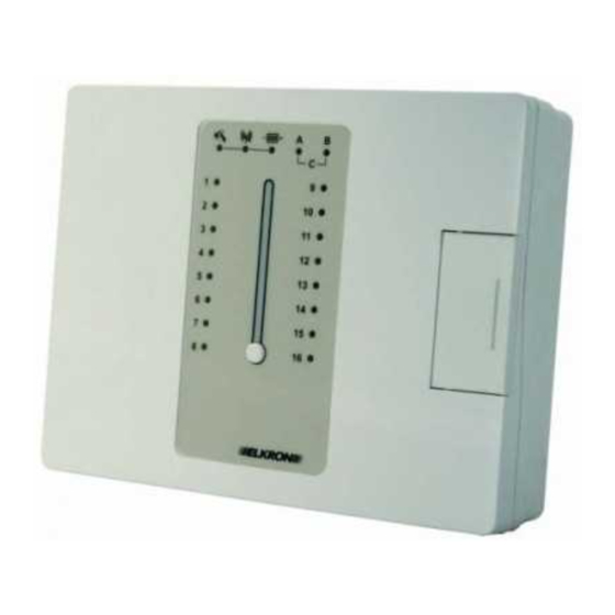
2 – USE 2.1 ELEMENTS OF RADIO MODULE MR16 Figure 1 1. LED for alarm warning 2. LED for identification of device typology 3. Status LED of corresponding input 1÷16 4. Control key Installation and use MR16... -
Page 9: Visual And Acoustic Warning
2.2 VISUAL AND ACOUSTIC WARNING 2.2.1 Visual warning Radio module MR16 front side is provided with LEDs displaying the status of system and its radio devices. Colour Meaning 1÷16 Status of corresponding Input open or movement Input closed or no... -
Page 10: Details On Visual Warning
Detection device open/closed status is immediately identified by its LED (there is one LED per input). Physical sabotage warning ( 1. Press once control pushbutton at the front side on radio module MR16: 3 beeps are sent out and stops blinking and is lit steady. -
Page 11: Warnings From Detection Devices
Battery low warning ( 1. Press three times control pushbutton at the front side on radio module MR16: 3 beeps are sent out and LED stops blinking and is lit steady. 2. Press control pushbutton and keep it pressed for 3 seconds: •... -
Page 12: Warnings From Actuation Devices (Sirens)
1. Press key on remote control: remote control LED will be lit in colour red. 2. Remote control sends out a beep to confirm that radio module MR16 received the command. If it did not, press key again to send the command again. -
Page 13: System Design
Warning: always displace peripheral unit (detector, siren, etc.), not radio module. To position the various devices, comply with following rules: • Radio module MR16: o must be mounted close to wired alarm control panel, possibly not on walls made of either concrete or integer bricks;... -
Page 14: Operating Modes
LED will blink until alarm details are checked. 3.2.4 Battery low condition Should one or more devices be in battery low condition, then radio module MR16 will react as follows: • LED will blink; • BATTERY relay output will be armed. -
Page 15: Installation
4 – INSTALLATION 4.1 RADIO MODULE MR16 4.1.1 Fastening 1. Open radio module MR16 as illustrated in figure 2. Figure 2 2. Prearrange passages cables connection wired alarm control panel. Radio module container base is prearranged with pre-fractured passages (figure 3): if rear passages and not side passages are to be used, first remove the electronic board, taking off the four screws that are placed at the corners (figure 4). -
Page 16: Connection To Power Supply
4.1.2 Connection to power supply Radio module MR16 takes power supply at 12 V— out of wired alarm control panel it is connected to. Before making the connection, check for wired control panel to be able to provide current requested by radio module, that is that overall absorption of control panel, devices, connected to control panel, and radio module does not exceed the current which control panel power supply unit is able to supply. -
Page 17: Connections To Wired Alarm Control Panel
Do not exceed voltages and currents accepted for solid state relays. The status of the relay at rest (normally open or normally closed) is defined by DIP switches (see paragraph 4.1.4 Configuration of radio module MR16 configuration). The LED between the two DIP switch banks indicates radio module MR16 armed/disarmed status. - Page 18 Relay output follows radio module MR16 armed or disarmed status. SYS ST This output can be used to display radio module MR16 status, e.g. by connecting an external LED. The polarisation of each output can be changed by modifying the position of corresponding jumper.
- Page 19 Tamper MR16 connection Terminal blocks TMP are a support to radio module MR16 tamper connection and must be taken back to wired anti-intrusion control panel. Figure 9 Installation and use MR16...
- Page 20 Connecting inputs Radio module MR16 is provided with inputs through which it can learn wired system status and receive commands from the system. Input polarity (reference to either positive or negative polarisation) is defined by DIP switch B6 (see paragraph 4.1.4 Configuration of radio module...
- Page 21 Green Device type Indicating that identification involved device is a siren Green Device type Indicating that identification involved device is a remote control ARM/DISARM Green MR16 status On steady: armed Lack of power Blinking: disarmed supply Installation and use MR16...
-
Page 22: Configuration Of Radio Module Mr16
4.1.4 Configuration of radio module MR16 Radio module MR16 operation is configured via DIP switch. Command Figure 10 DIP switches Function Settings A1 - A2 The switches arm wireless devices acquisition and removal normal operation steps acquire devices remove a device... -
Page 23: Supervision Function
2. Press the programming key of either micro contact or IR detector. The first of status LEDs 1÷16 that is free goes on and radio module MR16 sends out 2 beeps for confirmation. If radio module MR16 sends out one two-tone beep, it means that the limit was reached of devices that can be acquired and that no more devices can be added. -
Page 24: Fastening
To the input, more NC detectors in series (not in parallel!) can be connected, but just one shutter detector. Micro contact can be configured to use just internal detector, just external detector or both. Break micro contact shell near terminal box to allow cable passage. Connection cable length must not exceed 10 m. Installation and use MR16... -
Page 25: Configuration
During this step, its LED goes on blinking in colour red. When the LED goes off, you can go on with acquisition step. 4.3.2 Acquisition For IR detectors acquisition, see paragraph 4.2.2. Acquiring detection devices. Installation and use MR16... -
Page 26: Fastening
Figure 18 3. Add the 4 cells observing polarities. The siren will send out a short confirmation tone after last cell was added. 4. Put back cell holder opening cover and secure it with the screws. Installation and use MR16... -
Page 27: Acquiring Actuation Devices
Should radio module not send out any beeps, repeat point 3. 4. Set both DIP switches 1 and 2 of radio module MR16 to OFF to quit acquisition mode (radio module MR16 sends out one two-tone beep). Radio module MR16 automatically quits acquisition mode if no operations are performed for 3 minutes. -
Page 28: Configuration
The device is provided with pre-installed batteries. Loosen the screw at siren base and take off its covering. Set power supply to ON to supply the siren. Figure 20 4.5.2 Acquisition For siren acquisition see paragraph 4.4.2 Acquiring actuation devices. Installation and use MR16... -
Page 29: Fastening
3 minutes 3 -4 5 minutes 10 minutes 1 second for test reserved ON = reset (see paragraph 6.3.2 Reset sirens) OFF = normal operation reserved Figure 22 At end of configuration, close back the device. Installation and use MR16... -
Page 30: Remote Control Rc500
If radio module MR16 sends out one two-tone beep, it means that the limit was reached of devices that can be acquired and that no more devices can be added. -
Page 31: Test
When the device returns to its rest position, the LED remains on steady for DC500 and blinking for IR500 and DC500 auxiliary input. • Set DIP switch 3 to OFF to quit test mode; radio module MR16 will send out one two-tone beep for output confirmation. -
Page 32: Test Actuation Devices
MR16 and position it back elsewhere, if needed. 5.3 TEST REMOTE CONTROL Try to arm and disarm radio module MR16. One remote control beep will confirm that commands were received. 5.4 USER TRAINING After completing system installation, configuration and test, show the user how: •... -
Page 33: Maintenance
In order to remove one or more devices from radio module MR16: To remove a micro contact or IR detector 1. Make sure that DIP switches A1 and A2 of radio module MR16 are both to OFF. Should they not be, set them to OFF. -
Page 34: Replacing A Device
To remove a remote control 1. Make sure that DIP switches A1 and A2 of radio module MR16 are both to OFF. Should they not be, set them to OFF. 2. Set DIP switch A1 to OFF and DIP switch A2 to ON. -
Page 35: Opening Micro Contact Dc500
1. Loosen closing screw on detector lower side. 2. Take off front cover, which contains the detector and electronic part. For closing, operate in reversed way. Warning: in putting the cover back, check it to be correctly hooked before fixing closing screw. Installation and use MR16... -
Page 36: Opening The Battery Compartment Of Hp500 Siren
2. Set DIP switch B8 on radio module to ON, keep programming key pressed and power back the device. 3. All LEDs are lit and radio module sends out 2 beeps. Acquired devices are removed. 4. Set DIP switch B8 to OFF again: radio module MR16 returns to operation mode. 6.3.2 Reset sirens To reset a siren: 1. -
Page 37: Technical Characteristics
7 – TECHNICAL CHARACTERISTICS 7.1 RADIO MODULE WITH RELAYS MR16 Communication technology: Bidirectional radio frequency Radio communication mode: Frequency: 868.35 MHz Number of radio channels: Radio range: > 100 m in free air Supply nominal voltage 12 V— Control panel operation voltage 9 V—... -
Page 38: Micro Contact Dc500
1 2-colour LED Programming elements 1 programming/test key Case anti-opening protection Anti-tamper device Supervision interval 120 minutes Declared operation temperature -5°C ÷ +45°C Dimensions (W x H x D) in mm micro contact: 64 x 94 x 42 Installation and use MR16... -
Page 39: Indoor Siren Is500
1 lithium battery of type CR2032 with 3 V voltage Duration 2 years in normal use conditions Warning elements 1 2-colour LED Control elements 4 keys Declared operation temperature -5°C ÷ +45°C Dimensions (W x H x D) in mm 38 x 65 x 15 Installation and use MR16... -
Page 40: Default Settings
8 – DEFAULT SETTINGS System MR16 components go out of the default with following configurations: Radio module with relay MR16 Function Programming element Default Relay outputs 1÷8 polarisation Jumpers J1÷J8 12 V Relay output SAB polarisation Jumper J9 12 V... - Page 41 Operation mode DIP switch 1 OFF = normal Reserved DIP switch 2 Ringing duration DIP switches 3-4 OFF-OFF = 3 minutes Reserved DIP switch 5 Reset memory DIP switch 6 OFF = disabled Reserved DIP switch 7 Installation and use MR16...
- Page 42 Installation and use MR16...
- Page 43 Installation and use MR16...
- Page 44 ELKRON S.p.A. Made in Taiwan Via Cimarosa, 39 – 10154 Torino (TO) – Italy Tel. +39 (0)11.3986711 – Fax +39 (0)11.3986790 www.elkron.com – mail to: info@elkron.it Installation and use MR16...
Need help?
Do you have a question about the MR16 and is the answer not in the manual?
Questions and answers